Note: Descriptions are shown in the official language in which they were submitted.
CA 02534323 2006-01-27
WO 2005/011375 PCT/US2004/024081
APPARATUS, METHOD, AND SYSTEM FOR APPLYING SUBSTANCES TO
PRE-HARVESTED OR HARVESTED FORAGE, GRAIN, AND CROPS
I. BACKGROUND OF THE INVENTION
A. Field of the Invention
The present invention relates to application of a biologically active or
chemical
substance to relatively large volumes of target product, one example being pre-
harvested
or harvested crop, and in particular, to an apparatus, method, and system of
applying
biologically active or chemical substance in a minute ratio to the target
product, whether it
is moving relative to the substance, the substance is moving relative to it,
or both.
B. Problems in the Art
It is many times desirable to treat harvested agricultural crop by applying
substance
having, at least in part, some biologically active organisms. One primary
example is a
forage inoculant which contains bacteria that, when applied in appropriate
concentration to
harvested agricultural crop, can reduce rate of degradation of the harvested
agricultural
crop.
In the example of forage inoculant, a relatively small concentration of
inoculant
can effectively treat a relatively large volume of harvested crop. For
example, ratios on
the order of 40 grams of inoculant to 50 tons of harvested crop are typical.
However,
relatively effective even application of such small quantities to such large
quantities of
agricultural crop is not a trivial matter, particularly if the crop or the
applicator, or both,
are moving relative to one another.
Additives are in common use for purposes of aiding in the preservation of the
crop
during storage. Two types of additives are the most common: (1) acid to reduce
bacterial
activity and, (2) inoculants to add favorable activity. These additives must
be applied at
time of harvest to provide the maximum benefit in the aid to preservation of
the crop.
Harvesting of the crop takes place over a large area through the use of mobile
harvesting
equipment such as forage harvesting and baling implements. These implements
have been
designed for maximum speed in harvesting with very little consideration of
being
compatible with the requirements of applying the additives used to aid in the
preservation
of the crop. The carrying capacity of harvesting equipment for additives being
used is
sometimes limited to small amounts of material. In such cases, it is
beneficial to use
CA 02534323 2010-10-19
WO 2005/011375 PCT/1JS2004/024081
additives that require the lowest ratio of additive to crop so, with limited
carrying capacity,
the harvesting implement is not stopping to refill small reservoirs for the
additives on a
frequent basis.
Additives to aid in the preservation of crops have been developed with
increasing
lower ratios of application in recent years. High-strength acid formulas have
been
introduced that are effective in controlling bacterial growth when applied at
ratios a low as
0.005% of the crop being treated. Highly concentrated inoculants have been
developed
that are effective at rates as low as 0.001% of the crop being treated. These
low inclusion
rate products have reduced the need to stop and fill the reservoirs on the
harvesting
implements.
The problem that arises with the products that have low rates of application
is
attaining even coverage over the complete crop being treated. To be effective
on the entire
crop, coverage of these additives must be even on the entire crop. For
liquids,
conventional spray techniques are less than effective at these low rates.
One current method of inoculant application premixes concentrated inoculant
with
water in a large tank (e.g. 1:200 to 1:3000 ratio inoculant to water). Such
tanks can hold,
sometimes, on the order of 100 or more gallons of water. A conventional
spraying system
is then used to spray the mixture on the harvested crop. It is cumbersome and
time
consuming to mix, carry, and replenish such a large volume. It can also be
wasteful of
inoculant, which is biologically active and not inexpensive. Careful pre-
mixing must take
place. Sufficient power and fuel must be used to manipulate a tank of such
size and
weight. If the full tank of mixture is not used, the remainder most times must
be thrown
away. There is no practical way to store the mixture. Additionally, a
relatively accurate
spraying system must be used. The whole system usually must be taken back to a
base
location to refill and remix the tank. Such a spraying system uses a
substantial amount of
water per unit forage.
An alternative method was developed to address some of the aforementioned
problems and deficiencies. The APPLI.PROTM system available from Pioneer Hi-
Bred
International, Des Moines, Iowa, and disclosed at U.S. Patent Application
2002/0124541 and WO
99/58253, instead uses a palm or hand-sized APPL1PROTM container or bottle
(see -U.S.
Patent D409,303) of concentrated inoculant pre-mix that could be removably
installed to
its spraying system. A larger water tank is in fluid communication with a
first pump,
which pumps water from the tank at a desired rate to spray nozzles. A second
pump,
preferably an injection pump, is in fluid communication with the small
inoculant
2
CA 02534323 2006-01-27
WO 2005/011375 PCT/US2004/024081
concentration bottle and the fluid conduit. Precise, adjustable operation of
the injection
pump served as a precise metering of concentrated inoculant into the main
water stream to
the sprayers. This eliminated the requirement of pre-mixing in the large water
tank. It
allowed for dispensing of only the needed amount of inoculant. At the end of a
spraying
session, the inoculant bottle could either be exchanged or any remainder
sealed and stored
in that container, and then available for subsequent use. The system provides
accurate,
efficient utilization of inoculant with reduced margin of error. It is also
highly adjustable
for different needs. However, it requires two separate pumping mechanisms.
Additionally, it still uses a substantially large holding tank for the water
supply if large
quantities of agricultural crop were to be sprayed in one session.
Other attempts have been made at improved forage inoculant-type application
systems. In the ULVTM model, available from Pioneer Hi-Bred International,
instead of a
large water tank, either as a pre-mix tank or water supply tank, again a much
smaller single
container (e.g. 2.5 liters) contains the pre-mix of inoculant and water. Also,
instead of
spraying a ratio of a very small amount of inoculant to large amounts of water
an atomizer
is used to atomize the mixture in a very accurate, consistent manner to apply
the right
amount on the harvested forage. However, it has been found that an effective
atomizer is
relatively expensive, and that the overall apparatus can cost several
thousands of dollars.
Therefore, additional room for improvement in the art still exists. A more
economical, less cumbersome, efficient and effective application system is
needed. Other
factors must be considered in designing systems to apply such types of
substances.
First, many biologically active substances have some threshold of tolerance
for
trauma. For example, some pumps and nozzles that try to atomize fluid many
times
subject the living cells to shearing forces that can damage their cells. Of
course, damaged
inoculant cells can inhibit or destroy their efficacy.
Secondly, care must be taken to avoid over-drying the biologically active
substance, either while stored, awaiting application, or during application.
Excessive
drying or exposure to air can also reduce the efficacy of the biological
ingredient.
Third, even with the specific example of forage inoculants, there are a wide
variety
of environments in which the inoculant could be applied and environmental
factors could
affect application. For example, it could be applied on a harvested crop
moving past a
spray device on some sort of an exposed conveyor. Care must be taken to direct
the
inoculant in an even manner on the moving crop. Conveyance equipment is
becoming
more and more sophisticated. The crop can be moving at substantial speeds and
volumes.
3
CA 02534323 2010-10-19
WO 2005/011375 PCT/US2004/024081
An inoculant application system must be able to be adjusted and adapted
accordingly. For
example, the application system might be carried on-board a harvesting device.
Inoculant
application may be made at or near the internal conveying systems, e.g.
mechanical or
pneumatic, of the machine. The speed the crop moves can be high; for example,
over a
hundred miles an hour. With exposed conveyors or internal conveyors, the
effect of wind
or vacuum on an airborne mixture created by high-speed venturi effect must be
handled.
On the other hand, as detailed in U.S. Patent Application 2002/0124541 and WO
99/58253,
there are other instances where the application system may be moving relative
to the
harvested crop, or both the sprayer and the crop moving. An effective
application system
must be able to handle those environments.
For purposes of this description, the term "target product" will be used to
refer to
any material, living or not, or any surface to which the apparatus, system or
method of the
present invention could be used to apply a biologically active or chemical
substance in a
liquid pre-mix form. For purposes of this description, the term "crop" will be
used to refer
to an example of a target product, and includes any plant material, whether
pre-harvested
(e.g. growing in a field or cut but without the desired part being yet
harvested), or during
and after harvesting.
II. SUMMARY OF THE INVENTION
It is therefore a principal object, feature, advantage, and/or aspect of the
present
invention to provide an apparatus, method, or system of applying a
biologically active or
chemical substance in relatively small quantities to relatively large volumes
of a target
product that improves over or solves problems and deficiencies in the art.
Additional objects, features, aspects, and/or advantages of the present
invention
include an apparatus, method, or system for applying a biologically active or
chemical
substance in relatively small amounts to relatively large volumes of a target
product which:
a. is economical:
b. reduces the amount of carrier fluid that must be available or carried
to mix with the biologically active or chemical substance;
c. is adaptable to work with up to extremely large volumes and rates of
volume flow of target product, including crops;
d. avoids trauma on the biologically active or chemical substance;
e. is adapted for high throughput oftarget product;
4
CA 02534323 2006-01-27
WO 2005/011375 PCT/US2004/024081
f. is accurate;
g= is adjustable for different volumes and speeds of
different target
products;
h. is consistent and even in application;
i. is durable;
j. provides relatively easy maintenance and repairs;
k. is adaptable for a variety of placements, environments, and
functions;
1. provides an even mix and application by air assist.
These and other objects, features, aspects, and/or advantages of the present
invention will become more apparent with reference to the accompanying
specification
and claims.
One particular aspect of the present invention includes an apparatus, method,
and
system for applying a biologically active or chemical substance to a
relatively large
volume of target product, including crop. The biologically active or chemical
substance is
mixed with water. The mixture is contained in a relatively small, hand
carryable container
or bottle which can be placed in fluid communication with a conduit to a
nozzle with
spraying end. A pump is adapted to move the mixture from the bottle through
the conduit
towards the nozzle. Pressurized air is mixed with the mixture in the conduit
to aerate the
mixture. The pump is controllable and adjustable to vary the rate of
application of the
mixture from the nozzle. The nozzle, pump, and pressurized air are selected to
essentially
mist the mixture in a controlled, even, consistent manner, minimizing trauma
on any
biologically active or chemical ingredients. What might be called the "air
assist" promotes
an even discharge and application. A relatively low volume of liquid mixture
is precisely
metered onto the target product with a relatively large volume of pressurized
air. The
primary components of the system can be integrated into a relatively small-
sized unit.
In another aspect of the invention, a process employs a stream of air under
pressure
to deliver low rates of additives to crops, so that the air distributes the
additive to the crdp
evenly. The additive being applied, e.g. at ratios under 2% of the crop being
treated, is
thus evenly distributed, leading to more effective response to the additive.
In another aspect of the invention, voltage of the pump motor is monitored.
Adjustment of the voltage to the pump can then adjust the output of the
system.
In another aspect of the invention, the nozzle and aeration of the mixture
cooperate
with the pumping of the mixture to create a consistent, controlled spray or
distribution
5
CA 02534323 2006-01-27
WO 2005/011375 PCT/US2004/024081
without shearing action which can be harmful to the biologically active or
chemical
substance.
Another aspect of the invention includes the system's own ability of using air
pressure to clean the conduits of material post-application. This process can
be conducted
automatically.
The system can be used in combination with a variety of conveyance methods for
the system or the target product to which the substance is to applied, or
both.
III. BRIEF DESCRIPTION OF THE DRAWINGS
Figure 1 is a simplified diagram of one exemplary embodiment according to one
aspect of the present invention.
Figure 2 is a diagram of components of an exemplary embodiment according to
the
present invention with a single mixture container.
Figure 3 is a diagrammatic view of a double container system that could be
used
with the embodiment of Figure 2.
Figure 4 is an alternative embodiment for a double nozzle system useable with
the
system of Figure 2.
Figure 5 is an electrical schematic of an electrical circuit usable with the
embodiment of Figure 2.
Figures 6A-C are perspective views of one example of how certain components of
the system of Fig. 2 could be incorporated into an integrated apparatus or
housing.
Figure 7 is a diagrammatic view of a control interface for an embodiment of
the
invention.
Figure 8 is a simplified perspective diagram of an alternative embodiment
according to the present invention; an embodiment where the biologically
active or
chemical substance is applied in a swath of mown or cut crop in a field.
IV. DETAILED DESCRIPTION OF EXEMPLARY EMBODIMENTS
A. Overview
For a better understanding of the invention, examples or forms the invention
can
take will now be described in detail. Frequent reference will be taken to the
accompanying
drawings. Reference numbers will be used to indicate certain parts and
locations in the
drawings. The same reference numbers and letters will be used to indicate the
same parts
and locations throughout the drawings, unless otherwise indicated.
6
CA 02534323 2006-01-27
WO 2005/011375 PCT/US2004/024081
B. Exemplary Embodiment 1
With reference to Figure 1, in one aspect of the invention, an apparatus and
process
combines a high volume of air delivered to the crop and a low volume metering
of the
additive (e.g. a mixture of biologically active or chemical substance and
water) into the
stream of air to carry and distribute the additive into a crop. In a typical
embodiment of
the process, a means of pumping air 1 is mounted on harvesting equipment such
as forage
harvesting or baling implements. The airflow from the source 1, a pump,
compressor or
supply of compressed air, is normally between 0.1 and 5 cubic feet per minute.
It is
delivered into a line 2 and routed to a spray orifice 3. The orifice will
deliver the air in an
even fan-type pattern 4 when the air before the tip is delivered under
pressure, typically
between 5 and 100 pounds per square inch (psi). When this spray orifice 3 is
oriented in a
position on the harvesting implement where the crop is flowing evenly in front
of the tip,
the air/liquid mix covers the crop evenly.
In the typical embodiment, a reservoir 5 to hold the additive is also located
on the
harvesting equipment. A metering device 6 is used to dispense the additive
into the line 2.
The metering device 6 regulates the proper application of the additive based
on flow of the
product. The metering device 6 may also have a means of preventing air from
flowing into
the reservoir 5 and also must have the capability to deliver product into the
line 2,
overcoming the line pressure developed by the air supply 1. In a typical
embodiment, the
metering device 6 used is a positive displacement pump, which will prevent air
from
entering the reservoir 5 and will deliver product at a pressure high enough to
overcome the
air pressure in the line 2. This pump can be equipped with a means to regulate
flow, so
that the amount of additive discharged to the crop is matched to the rate of
harvest, and the
desired ratio of application can be maintained. Distance from the point of
introduction at
the metering device 6 and the spray tip 3 must be of sufficient length to
allow for mixing
of the product in the air before it is delivered to the crop.
An encoder could be used to monitor application rate, a voltage adjustable
motor to
control metering of the concentrate, or other devices to monitor and manage
application.
C. Exemplary Embodiment 2
1. Exemplary Environment
With reference to Figures 2-7, other aspects according to the invention will
be
described. In this example, an additive (an air/liquid mix including a
biologically active
substance mixed with water) will be applied to a harvested agricultural crop,
which will be
forage such as alfalfa. The biologically active substance will be a forage
inoculant (e.g.
7
CA 02534323 2006-01-27
WO 2005/011375 PCT/US2004/024081
1174 silage inoculant, available from Pioneer Hi-Bred International, Inc., Des
Moines,
Iowa)
The apparatus for carrying and applying the mixture on harvested forage is a
self-
propelled or pull-behind (including loader wagons) forage crop chopper vehicle
or
implement (such as are well-known in the art), with the spray nozzle
positioned along an
internal conveyor or pneumatic movement of the harvested forage. A control
device is
positioned at or near the operator of the vehicle or implement.
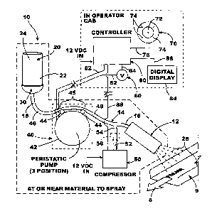
Figure 2 is a diagrammatic illustration of a system 10 according to this
exemplary
embodiment. The components are in diagrammatic form for illustration and are
not to
scale. Forage is diagrammatically illustrated passing through an internal
conveyor 9 of the
chopper in the direction indicated by the arrow 8 in Figure 2. Components in
the upper
right hand part of Figure 2 are located in a operator cab. The remainder of
the system is
located at or near the material to spray, internally of the harvester vehicle.
Of course, the apparatus, system, and method can be used for other analogous
applications and in other environments, as indicated herein. This is one
example only..
The basic primary components of system 10 will now be described.
2. Bottle 20
A 2,500-milliliter bottle 20 (basically cylindrical) with a first end 22 and a
second
end 24, is adapted to hold a mixture of carrier fluid (e.g. water) and
biologically active or
chemical substance (e.g. forage inoculant). As can be seen in Figure 3, bottle
20 can have
an opening 26 in end 22 through which the water and inoculant can be inserted
into bottle
20 and mixed (by shaking or other methods), or a pre-mix of water/inoculant
could be
inserted into bottle 20. A removable cap 25 is illustrated in Figure 3 (e.g.
could be placed
onto the top of bottle 20 and removably cover and seal opening 26). Bottle 20
could be the
AppliProTM bottle from Pioneer Hi-Bred International, Des Moines, Iowa (USA).
It could
have a configuration like that of U.S. Patent D409, 303.
The inoculant is available from a variety of commercial sources in highly
concentrated form. Through empirical testing or knowledge, the application
amount from
system 10 can be determined. The ratio of inoculant to water in bottle 20 can
be calculated
so that the required ratio of inoculant to volume of forage is met when system
10 is
operated.
One example would be to treat about 250 tons of harvested forage per hour. A
ratio of approximately 1 part inoculant to 6 parts water for a 2,500-
milliliter bottle (e.g.
reference number 20 of Figure 2) would be typical. The 250 tons/hour is based
on the
8
CA 02534323 2010-10-19
WO 2005/011375 PCT/US2004/024081
assumptions that: (a) system 10 is configured to mist approximately 10
milliliters per ton;
and (b) there would be approximately 100 Billion colony forming units (CFU)
per ton of
forage moving at medium or high speeds through the spraying area.
Bottle 20 can be made of any of a number of materials. One example would be
high impact, transparent UV resistant plastic that can be sterilized with
traditional
procedures.
As can be appreciated, a 2,500-milliliter bottle is easily carryable, even
when full,
by one or two hands of a person. Several bottles 20 could be carried by a
single person at
least in a box or carrier. Bottle 20 could include indicia with instructions
or identification.
Furthermore, as can be appreciated, a friction fit, sealable cap 25 would
allow
mixture in bottle 20 to be stored for some reasonable time, as opposed to
having to throw it
away if not used up in a given application session.
3. Bottle Receiver 30
As shown in Figure 2, and with further reference to Figure 3 (left side),
system 10
includes a receiver 30 adapted to accept and receive the end 22 of bottle 20
with opening
26. Threads 38 on bottle 20 could mate with threads in concave receiving cup
32 of
receiver 30 to allow removable securement of bottle 20 to system 10. Receiver
30 could
be operable in the position shown in Figure 2, with bottle 20 inverted such
that fluid would
fill by gravity into conduit 14. Alternatively, as indicated in Figure 3,
bottle 20 could be
threaded, with opening 26 up, into receiver 30. A tube 34 could extend down
near the
bottom of bottle 20 when in fully attached position and suction or vacuum
effect of pump
40 could draw fluid from bottle 20 up into conduit 14.
U.S. Patent Application 2002/0124541 and WO 99/58253 illustrate in more detail
several embodiments of a receiver/bottle arrangement 20 such that could be
used with
system 10. In particular note that receiver 30 could be rotatable such that
bottle 20 could
be threadably inserted with end 26 up so that no spillage occurs, and then the
entire
receiver/bottle 30/20 combination rotated such that bottle 20 ends up open-end-
down to
feed its contents by gravity. Or the entire receiver/bottle 30/20 could remain
in the fixed
upright position. Furthermore, U.S. Patent Application 2002/0124541
illustrates certain ways
that flow could be controlled from bottle 20.
Receiver 30 can be made of relatively economical materials such as molded or
extruded plastics that are highly durable and resistant to the environment
they would
experience.
9
CA 02534323 2006-01-27
WO 2005/011375 PCT/US2004/024081
4. Conduit 14 And Nozzle 12
As illustrated in Figure 2, main fluid conduit 14 has a distal end 16 attached
to a
nozzle 12, and a proximal end 18 in fluid communication with bottle 20 through
receiver
30. System 10 is operable to move mixture from bottle 10 into end 18 of
conduit 14, and
to end 16 of conduit 14 for spray distribution from nozzle 12. Conduit 14 can
be a
durable, transparent, flexible plastic tubing (e.g. hospital grade) adapted to
work with a
peristaltic pump. It can vary in length and dimensions according to need. In
one example,
it is a 8 feet long, 1/4 inchI.D., 3/8 inch O.D. flexible tube made from one
of various
plastics types or PVC and is available commercially from Grainger Co. of
Davenport,
Iowa under product number/name 4HL94.
Nozzle 12 can be different styles or configurations. Preferably, it produces a
gentle, consistent mist under the pressure and input conditions of system 10.
It does not
create atomization through micro screens or sharp corners and constrictions in
a manner
that could provide damaging trauma on a substantial scale to the cells of the
inoculant, or
provide shearing action to the cells that would tend to damage them. It
promotes even
distribution into the space through which forage 8 is moving (see reference
no. 28 in Fig.
2). In many present-day forage implements, forage 8 moves relatively quickly
past nozzle
12 (e.g. sometimes well over one hundred miles an hour). Many implements use
pneumatic power to move forage 8, so it is basically fluidized in pressurized
air. It
therefore is not lying flat, but is moving fast through all parts of a cross-
section of the
pneumatic conduit. This presents a challenge for even application to forage 8.
Some
implements use mechanical conveyors. Forage 8 would then be more in a form
that is
lying on the conveyor. This also presents a challenge to even application.
An example of nozzle 12 would be a spray nozzle sold under the trademark
ConeJet available commercially from Tee-Jet Co. and Spraying Systems Co. of
Wheaton,
Illinois. One such nozzle that has been used is marked "ConeJet 10X". Other
types are, of
course, possible. Preferably, they do not present substantial trauma to the
cells of
biologically active substances.
5. Pump 40
Pump 40 is a peristaltic pump having a motor 42 and a peristaltic roller
mechanism
44, such as are well known and available commercially. An example would be
part no.
2P305 peristaltic pump from Grainger Co. of Davenport, Iowa (12 VDC). It is
electrically
CA 02534323 2006-01-27
WO 2005/011375 PCT/US2004/024081
powered and motor 42 could have a variable speed motor control to the motor
speed of
motor 42, and thus the pumping rate of pump 50.
Conduit 14 would be in fluid communication with bottle 20 and nozzle 12. It
could
be a single plastic tube passing through peristaltic pump 40, or could have
one piece
operatively connected between bottle 20 and an input 46 to a piece inside pump
40, and
another piece between output 48 of pump 40 to nozzle 12. Obviously, conduit 14
and any
connectors, whether conduit 14 is a unitary member or in segments or pieces,
are fluid
tight from bottle 20 through nozzle 12.
Operation of peristaltic pump 40 in a normal pumping mode would successively
constrict a portion of flexible conduit 14 at area 45 (generally between pump
rollers 44) to
create a pumping action in conduit 14. Motor 42 would be adjustable to vary
the speed of
the peristaltic rollers 44, which would be in proportion to the amount of
fluid that would be
pumped through conduit 14.
Adjustment of pumping rate can be calibrated for the substance and target
product.
Many harvesting implements have sensors which can estimate the amount of tons
of crop
being harvested per hour. The amount of mixture to be applied per ton
harvested crop per
hour can be predetermined. The pumping rate of pump 40 can be calibrated for a
range of
application rates per ton harvested crop per hour. An operator of the
harvesting equipment
can check the estimated tons/hour the harvester will be processing and then
simply punch
in or dial in a correlated setting for system 10. If the rate needs to be
changed because of a
change in tons/hour being harvested, or for a difference crop or target
product, a variable
speed pump allows the same.
6. Compressor 50
Pressurized air is introduced into conduit 14 between pump 40 and nozzle 12
through conduit 52 from compressor 50 to junction 54 with conduit 14. Conduit
52 can be
of the same or similar material as conduit 14. A fluid-tight "T" joint or
other connection
can be made at junction 54. Alternatively, conduit 14 could be originally
manufactured to
have branches 16 and 52.
Compressor 50 can be part number 5Z349 available from Grainger Co. of
Davenport, Iowa. Preferably, it produces 5-30 psi at 12 VDC. A range of 5-50
psi has
been found acceptable, but a range of 5-100 psi can be used. Preferably,
branch 52 is
protected by a one-way valve or otherwise has an apparatus that prevents the
mixture from
traveling into branch 52 or into compressor 50.
11
CA 02534323 2006-01-27
WO 2005/011375
PCT/US2004/024081
The psi from compressor 50 can be adjustable and compressor 50 can be operated
on 12 VDC. Alternatively, or in addition, another component could be added to
the
system that would allow adjustment of air pressure from compressor 50 (e.g.
some type of
pressure control device at or after the outlet from compressor 50).
7. Voltmeter 60
A conventional voltmeter 60 (one such is part no. IT-855 from Grainger Co.)
can
be in electrical communication by cable 62 with motor 42 of pump 40. By
empirical
testing and calibration, the amount of throughput of mixture from bottle 20 to
nozzle 12
can be correlated with the voltage reading of motor 42. Alternative voltage
sensors, e.g. a
digital volt-meter, may be used as well.
Cable 64 can communicate the voltage reading of voltmeter 62 to a controller
80
(see Figure 2).
As mentioned previously, motor 42 would present voltage readings that can be
correlated with a varying amount of throughput of fluid through conduit 14.
Therefore, by
the simple method of monitoring voltage of motor 42, intelligence can be
gathered about
the rate of mist from nozzle 12.
There can be alternative ways to calibrate the system and operation of motor
42
without voltmeter 60 and its function.
8. Manual Control 70 and/or Control Interface 110
Because mist output has a known relationship to operating voltage of pump 42,
manual control 70 can be operatively connected to motor 42. A manually
adjustable
control knob 72 can be adjusted to different settings 74 for control 70 to
provide a range of
pump speeds (i.e. motor speeds), to in turn adjust rate of pumping action from
pump 40.
One alternative would have control 70 (e.g. a rheostat) directly adjust speed
of
motor 42. The operator would have to set control 70 based on empirical tests
or
calibration.
Another alternative, as shown in Figure 2, has control 70 operatively
connected to
an intermediary component, here controller 80, which would translate the
setting of control
70 into a signal that would instruct the speed of motor 42 through a cable,
electrical wire,
or other communication channel 82. A cable, electrical wire, or other
communication
channel 76 can connect control 70 to electronic controller device 80.
Another option would be to have a control interface associated with controller
80
(see, e.g., control interface 110 of Fig. 7) which would allow an operator to
set application
12
CA 02534323 2006-01-27
WO 2005/011375
PCT/US2004/024081
= rate by pushing or touching buttons or screens or other input devices.
Software could be
programmed to interpret the operator input and instruct pump motor 42
accordingly.
9. Controller 80
System 10 can be coordinated through a controller 80. Controller 80 can be a
microprocessor, such as are well-known and commercially available. Other types
of
electric, electronic, or digital controllers are possible. It could include a
digital display 84
integrated with controller 80 or connected through a cable 86. Controller 80
can operate
on 12 VDC. As mentioned, adjustable inputs directly on digital controller 80
may be used
in place of a rheostat 70.
Controller 80, along with manual control 70 if used, can be integrated into a
housing that can be positioned in the operator cab of the agricultural
equipment (e.g.
chopper). Voltmeter 60, if used, can be integrated into the housing or
positioned near
pump 40, or anywhere in between.
Controller 80 could be programmed by well-known means and methods to interpret
and instruct pump motor 42 to operate at a selected setting of control 70 and
monitor
voltage of motor 42 to maintain a consistent pump motor 42 speed. An example
of
operation is provided later.
Alternatively, controller 80 could be programmed for more sophisticated
functions.
For example, it could have either a volatile or non-volatile memory with look-
up tables
correlated to various application rates. Instead of a manual control 70, the
operator would
simply enter an input instruction that controller 80 would interpret to be a
given
application rate. Controller 80 would then, in turn, instruct operation of
pump 42
accordingly. Voltmeter 60 could effectively be a feedback loop to controller
80 to monitor
the pump operation and thus allow controller 80 to fine tune the mist output.
Memory could also contain application rates and ranges for a variety of
different
biologically active or chemical substances.
Optionally, controller 80 and other electrical or electronic circuitry or
components
could be manufactured, in whole or in part, into a circuit board that could be
installed in a
housing for operable use with apparatus 10. This could further reduce cost of
the system.
10. Electrical Circuit
Figure 5 schematically illustrates generally an electrical circuit 100 that
can be
used with system 10. Circuit 100 electrically communicates between the
components of
Figure 2 and a 12VDC electrical power source.
13
CA 02534323 2006-01-27
WO 2005/011375 PCT/US2004/024081
For example, Figure 5 illustrates the following components. It could include
additional components.
A switch 114 can provide electrical power to the circuit. A switch 115 can
turn the
spraying mode on. An input 117 can automatically pause the spraying mode by
disconnecting power to pump 40 and compressor 50 when a signal is received at
input 117.
Input 117 here is an "end of row input", which can be a signal from a micro-
switch or
other component on the harvesting implement indicating the harvesting head of
the
implement has been raised. This, in turn, indicates that harvesting has
stopped.
Conversely, the circuit can automatically resume spraying mode when the
harvesting head
drops, which can be sensed and signaled to circuit 100.
A variable speed control 43 for pump motor 42 of pump 40 can be set to control
rate of pumping action of pump 40.
Figure 5 also illustrates two valve control solenoids 104 and 106 which could
be
used to turn valves (not shown) on and off by instruction from controller 80.
Details of
their operation are provided later. Solenoids 104 and 106 can be used to open
and close
pathways for pressurized air and fluid on conduit 14. Solenoid 104 can be
normally closed
to block and seal conduit 52 to compressor 50 when it is not operating.
Solenoid 106 can
operate in concert with solenoid 104 for an optional clean out mode for system
10, as will
be discussed later. A timing relay 118 can be used to control a cleanout relay
119, which
in turn can control actuation of cleanout solenoid 106. Timing relay 118
essentially can
operate for a fixed period of time (e.g. 30 seconds) to run an automatic
cleanout mode if
instructed by controller 80.
11. Integrated System/Housing
Figures 6A-C illustrate one way some of the components of device 10 can be
integrated into a relatively small housing 200 (e.g., sheet metal) that can be
installed on a
vehicle or wherever else could be useful. A mounting plate 202 provides a
surface that can
be bolted or otherwise mounted on vehicle or wall or other surface. A header
90 could
include a receiver 30 for one or more bottles 20. In Figures 6A-C, two APPLI-
PRO TM
bottles 20A and B can be screwed into operative position to receivers 30A and
B
respectively. This provides easy access for the operator to connect or remove
either bottle
20A or B to device 10. As indicated at Figure 6C, a door 201 in housing 200
allows access
to pump 40, compressor 50, and other components (e.g. solenoids, valves,
tubing),. A
wall 208 can separate and essentially seal off compressor 50 from pump 40.. A
circuit
board could contain much of the circuitry indicated at Figure 5, but would
usually be
14
CA 02534323 2006-01-27
WO 2005/011375 PCT/US2004/024081
mounted in an enclosure in the operator cabElectrical connections would
communicate
operating instructions to pump 40 and compressor 50 in housing 200. Conduit 14
and
conduit 52 are not shown specifically in Figure 6C, but would form fluid
pathways from
bottles 20A and B and compressor 50, respectively, to a fluid outlet 210 from
housing 200.
The branch of conduit 14 to nozzle 12 (not shown in Figure 6C) would
operatively connect
to fluid outlet 210.
As indicated in Figure 2, controller 80 and other components could be located
remotely from housing 200 (e.g. in the operator cab of the vehicle).
Conventional
electrical communications (wire or wireless) could communicate instructions or
information from the in-cab components to housing 200 to, in turn, instruct
operation of
solenoids 104 and 106, pump 40 and compressor 50.
Figures 6B and C show an optional pressure gauge 204 could be operatively
connected to conduit 14 to monitor pressure during operation of system 10. It
should be
noted it could be placed in any of a variety of positions. It could
communicate with
controller 80 to provide real-time information to the operator in the cab. As
an alternative,
a digital readout on the controller could also give a pressure indication.
As can be seen in Figures 6A-C, most of system 10 can be integrated into a
relatively compact single housing 200 that would be relatively easy to mount,
even in
sometimes cramped interior spaces of a vehicle or implement. With relatively
few
connections, housing 200 can be in communication with controller 80 and nozzle
12. This
provides easy and non-cumbersome installation, set-up, and maintenance. It
also allows
removal of system 10 and installation into another vehicle or place with
substantial ease.
As can be appreciated, the components of system 10 could be predominantly
modular in nature, and thus present efficiencies in manufacturing,
maintenance, repair, and
replacement.
D. Operation
In operation, system 10 can function as follows. There would be preliminary
steps
such as below.
Bottle 20 would be filled with a mixture of water and inoculant according to a
priori knowledge or recommended instructions for a given application rate,
crop and/or
inoculant. The operator could, by hand, uncap bottle 20, and connect it to
receiver 30.
Prior testing is used to program controller 80 such that manual selector 70,
or in
this example, user control interface 110, would provide the operator with the
ability to
enter any of a range of application rates programmed into controller 80.
CA 02534323 2006-01-27
WO 2005/011375 PCT/US2004/024081
Nozzle 12 would be pre-positioned adjacent the flow path of forage 8. Of
course,
the spray pattern of nozzle 12 can be tested, its spray pattern established,
and the position
of nozzle 12 adjusted to get desired coverage relative moving forage 8 (Figure
2) without
wastage or over-spraying.
Some design is needed as far as placement of the components internally of the
vehicle. In one embodiment, bottle 20, receiver 30, pump 40, compressor 50,
and the
majority of conduit 14 could be enclosed within a housing or framework like
housing 200
of Figures 6A-C and inserted near the desired position of nozzle 12 in a
location that will
not come into conflict with other operating components of the vehicle.
Alternatively, any
or all of the components can be mounted in desirable positions and operably
interconnected.
By referring to the electrical schematic of Figure 5, electrical power to
various
components could be obtained by a connection to the vehicle's battery power
system
(usually 12 VDC) or otherwise converted to 12 VDC so that system 10 does not
need a
power source external of the vehicle.
The advantages of system 10 would therefore include a relatively small-sized,
interchangeable, removable bottle 20 that could be handled by hand, in
combination with a
fluid pump and air compressor to provide an aerated fluid flow to produce a
mist of even
consistency and application; all without having to use an atomization or
atomizer structure
or method, which can be expensive and could be detrimental to biological cells
or life
forms.
Controller 80, or some other intelligent device, can be used to not only
instruct
operation of components like pump 40, but also coordinate operation of the
system and
provide intelligence regarding settings or operation for the various
components for a given
mixture, crop, and throughput of crop. For example, sensors like a voltmeter,
pressure
gauge, or others could send information to controller 80 which could be used
by its
programming to control system 10.
The general rules for operation are as follows:
a. Eliminating atomization to reduce shearing action or trauma that could
damage bioactive or chemical substances.
b. Maintaining a closed system between the mixture in bottle 20 and nozzle
12
deters any drying action that could be detrimental to biologically active or
chemical substances.
16
CA 02534323 2006-01-27
WO 2005/011375 PCT/US2004/024081
c. Elimination of an atomizer or certain types of pump, and introduction of
pressurized air, deters high temperatures for the mixture, which also could
be detrimental to a biologically active or chemical substance.
d. Rate and consistency of spray can be relatively precisely controlled by
operation of pump motor 42 and amount of pressurized air 50.
e. Size, weight, and cost of system 10 are relatively small compared to
existing typical systems. Elimination of a large multi-gallon tank
eliminates a lot of weight and size issues. Additionally, elimination of a
hundred gallon tank or water container eliminates a safety issue because
such a tank adds a significant amount of weight to a vehicle and could
create tipping problems.
f. The rather compact size of the system allows it to be placed
advantageously
relative to the crop to be sprayed, including internally of vehicles. This can
eliminate the need for applying the substance to the crop in external
positions of the vehicle, which then brings into play environmental factors
such as wind that could affect the mist. Additionally, utilizing the
pressurized air from compressor 50 allows the system to be placed in
environments that pull a vacuum. The mist will still work effectively.
One specific description of components and operation according to one
exemplary
embodiment is as follows. The controller 80 can output motor functions to a
peristaltic
pump 40, air compressor 50, and solenoid valves in an application system for
crop
inoculant, such as has been previously described.
A. Physical specifications:
1. Peristaltic pump 40: 12 volt DC gear motor 42 runs between 300 and 1800
rpm and draws a maximum of 3 amps. The pump will be located 8 feet
away from the controller 80. The distance of the pump from the controller
80 may vary in distance. The controller80 will regulate motor speed to
control output.
2. Compressor 50: The controller80 will turn the compressor on and off
only.
12-volt power at 15 amps will be supplied to the compressor externally.
Optionally, a pressure control device or PCD (available commercially -- see
component 56 in dashed lines in Figure 2) could be used to adjust the
amount of air pressure from compressor 50 to conduit 14. PCD 56 could be
17
CA 02534323 2006-01-27
WO 2005/011375 PCT/US2004/024081
controlled by controller 80 if desired, through a solenoid or other
electronically-controlled device. Alternatively, it could be manually
operated or perhaps even by automatic adjustment via sensors.
3. Solenoid valves: There will be two solenoid valves to control the
direction
of airflow. Control to these valves will be to energize a 12-volt coil of
valve control solenoids 104 or 106, opening up a normally closed valve that
will require 0.2 amps to maintain the open position for an interval (e.g. 30
sec.). Power to the solenoids 104 and 106 will be activated by the
controller 80 for an interval of 30 seconds.
4. Display of control user interface (see Figure 7): The controller 80 will
have
a display 112 that shows motor speed setting and the accumulated
revolutions of the motor based on a calculation of motor speed and duration
of operation. These values will be displayed as a function of harvesting
units, which is derived by simple math from the motor speed setting. A one
line 4-character display with LCD numbers at 0.5-inch character height
could be used, or other styles and configurations of display. If possible
without significant cost, the display will also include a reading to give an
indication of line pressure. The purpose of this pressure display is to
provide the operator with a warning of possible plugging. Therefore
absolute accuracy in pressure reading is not required.
5. Enclosure 200: The unit will be installed in tractor cabs requiring dust
and
moisture resistance similar to a Harvest Tec 477 acre meter (available from
Harvest Tec, Hudson, Wisconsin). The vibration requirement for the
controller 80 should be good enough to provide years of dependable service
without vibration induced breakdowns. Consideration should be made for
conditions under which the unit will be operated.
6. Power supply: The controller 80 will be powered off the tractor's 12-
volt
power system that will deliver between 11 and 15 volts of DC power.
7. Cabling: Power input will be plugged into the bottom of the box. Motor
output and compressor output will be plugged into the bottom of the box.
Amp connectors will be used on both connections. Connections between
the pump housing and the control box should be some type of couplers,
screw on, or quick disconnect which will enable the operator to interchange
units easily and fairly quickly.
18
CA 02534323 2006-01-27
WO 2005/011375 PCT/US2004/024081
8. Switches: A membrane face overlay with four membrane switches 113,
114, 115, and 116 (see Fig. 7) will be over-laid on the box face.
9. Start/stop: Operation will be controlled by either a box-mounted switch
115
or from a remote signal that activates with 12-volt positive input.
B. Control operation (refer to Figs. 2, 5, and 7):
1. Power up and start non-operating part of "on" cycle. A push of "on/off'
button 114 is essentially the "power" button for system 10 and enables the
supply of electrical power to controller 80. This initiates a what will be
called the non-operating part of an "on" mode or cycle, where the display
becomes lighted and the "set rate" and "read/reset tons" functions
(correlated with buttons 113 and 116 on control interface 110) are enabled.
2. Clean functions. There are times when it is desirable to clean up
conduit 14
and nozzle 12. In this embodiment, when power button 114 is pushed off,
controller 80 will automatically initiate an automatic clean mode or cycle.
It does this by activating the two solenoids 104/106 and the compressor 50
for a pre-determined, pre-set interval (e.g. 30 seconds). The solenoids set
valves in the fluid paths between compressor 50, nozzle 12, and bottle 20 so
that the following can occur. Pressurized air from compressor 50 is allowed
to travel to nozzle 12. This will remove any fluid from that part of the fluid
pathway and clean out nozzle 12. Controller 80 would also instruct pump
40 to operate, but in a reverse flow mode. This would move any fluid in
line 14 back towards or into bottle 20. If the power is re-activated during
the 30-second automatic clean period, the 30-second interval will be
completed before normal operation is resumed. During the 30-second
interval, display 112 will flash "clean". Also, anytime during the "on"
cycle, if on/off button 114 is pushed and held for 3 seconds, controller 80
will activate a manual clean mode or cycle. Controller 80 will supply
power to solenoids 104/106 as described immediately above and run the
compressor 50 until on/off button 114 is pushed again. Display 112 will
flash, "clean" during this mode. This allows the operator to run a clean out
by manual selection. As can be appreciated, controller 80 could be
programmed to automatically run a clean mode at any time.
19
CA 02534323 2006-01-27
WO 2005/011375 PCT/US2004/024081
3. Set rate function. After power up and enablement of it, the "Set Rate"
-
function will be activated in what will be called the non-operating "on"
mode, meaning the spraying function of system 10 is not allowed. The
operator can then set a desired application rate for the mixture. Pushing
"set rate" button 113 will show the rate set on display 112. Holding "set
rate" button 113 in will scroll display 112 between the range of values 10
and 400; in 2 unit increments between the sub-range 10 and 100, and in 10
unit increments between the sub-range 100 and 400. When the unit gets to
value 400, it will roll over to 10. Scrolling will be at an accelerated rate
of
4 to 10 characters per second during the hold down interval. When button
113 is released, the motor speed for pump motor 42 will be set. This speed
setting will be accomplished by modulating the ground on the power to the
gear motor 42. There can be a look-up table with values of voltage versus
pump output. The operator thus selects an application setting via control
interface 110 appropriate with a desired rate of application for the given
inoculant/water mixture in bottle 20 and the forage speed and volume.
4. Tons treated function. After power up and enablement of the "Tons
treated" function, pushing "tons treated" button 116 will cause controller 80
_
to read the theoretical revolutions of the gear motor for the set "rate value"
off of the look-up table. This value will be multiplied by the minutes run
and converted to a tons value for display 112. This "tons treated" function
can assist the operator, if needed. Resetting the value is accomplished by
pushing and holding button 116.
5. Start operating part of "on" cycle. When the vehicle begins harvesting
the
forage, the operator would turn on the spraying function of system 10 via
switch 115. After the non-operating part of the "on" cycle is completed,
with the operator having set the application rate, a push of "start/stop"
button 115 will begin the operating part of the "on" cycle, where the
mixture is sprayed. Controller 80 energizes both pump 40 and compressor
50, and sets solenoids 104 and 106 so their respective valves allow fluid
from bottle 20 and pressurized air from compressor 50 to mix and move to
and out of nozzle 12. Pump 40 would pull mixture from bottle 20 at the
desired rate. Compressor 50 would aerate the mixture at a preset amount.
Controller 80 would send a signal via cable 82 to pump motor 42 of pump
CA 02534323 2006-01-27
WO 2005/011375 PCT/US2004/024081
40 to operate at a speed proportional to that selected. At the same time,
compressor 50 could be instructed by controller 80 to begin operation. The
aerated mixture would then be misted out of nozzle 12 as forage 8 passes by
the location of nozzle 12 to distribute the selected amount of mixture on
forage. In one example, 10 milliliters/ton of forage additive would be
applied. In one embodiment, capacity of system 10 is 400 to 600 tons per
hour (tph) top end. Typically, 150 -300 tph would be treated. During the
"run" mode of this operating part of the "on" cycle, display 112 will show
the accumulated tons treated. The operator can stop spraying by pushing
button 115. During this "stop" state or mode, display 112 will read "stop".
The operator will thus have a visual indication of state of spray. A remote
signal to 12 volt positive will perform the same function as the "start/stop"
key 115. As previously mentioned, the system could be programmed to
start or stop automatically if so desired (e.g. by response to dropping of
harvesting head).
This air assisted arrangement allows for precise, efficient, economical
control of
rate and distribution of the mixture with control over temperature, shearing,
and drying.
E. Options And Alternatives
The foregoing detailed description is of but one form the invention can take.
Variations obvious to one skilled in the art are included in the invention,
which is solely
described by the claims herein.
For example, variations in each of the components are possible. Dimensions,
specifications, and characteristics can vary according to desire and need.
As previously stated, the invention can be used for spraying forage inoculant
on
harvested forage, but could also be used to apply other types of mixtures that
include
biologically active or chemical substances on other harvested agricultural
crops, or other
products or things. Or the invention can be used to apply mixtures before a
crop is
harvested. For example, it could be applied to a swath of mowed forage before
it is picked
up and chopped. It could also be used to apply a mixture to a swath or row(s)
of growing
plants.
21
CA 02534323 2006-01-27
WO 2005/011375
PCT/US2004/024081
Some examples of other substances for application to target product include,
but
are not limited to, insecticide, herbicide, fertilizer, paint, cleaning
fluids, coatings, freeze-
drying. Other are possible.
An example of a different use of system 10 from that installed on a harvesting
implement is shown in simplified form at Figure 8. A system 10 (such as shown
in Figure
1 or 2) could be mounted on a frame 120 that has connections to the three arms
122, 124L,
and 124R of a three-point hitch of tractor 126. System 10 would include a
container 20, a
pump 40, a compressor 50 and a controller 80 like previously described. A hood
128 is
also mounted on frame 120 with at least one (here there are two) nozzle 12
positioned so
that the outlet of the nozzle(s) are inside hood 128. Appropriate wiring and
fluid conduits
connect the various components in a similar manner as discussed previously.
The
arrangement of Figure 8 is configured so that it can be moved by tractor 126
over a swath
of mown hay or silage of about three feet wide and apply a mixture from
container 20 to
the swath in a manner such as has been previously described. Hood 128 helps
contain the
mixture as it moves out of nozzles 12L and 12R, and helps prevent wind or
debris from
affecting the application. System 10 can be adjusted up or down relative to
the swath by
conventional operation of the three-point hitch.
Analogous structure could be used to apply mixtures to cut or growing crops,
but
not yet harvested ("pre-harvested"). For example, the system 10 could be
mounted to the
front of a vehicle (e.g. by a frame or connection to the front of a tractor or
other
implement). It could be operated to apply a substance on crop, whether growing
in the
field or cut and laying in the field, as the vehicle drives by or over it.
As previously stated, harvesting equipment exist that are self-propelled and
direct
harvested crop into an on-board bin, a wagon pulled by the harvester, or a
wagon pulled
along-side the harvester by separate tractor. There are also harvester
implements that are
pulled behind a tractor and direct harvested crop into a following wagon
(either hooked to
the implement or moving with the implement). There is also a type of harvester
equipment
sometimes called a loader wagon, which is pulled behind a tractor but combines
a
harvester with a wagon. System 10 could be placed in the entrance to the
loader wagon or
its outlet, and be used to apply substances to silage as it enters the wagon
or as it leaves the
wagon for placement in a silo or other storage location. The invention can be
applied to
any of these versions of harvesting equipment.
A system 10 could also be operably positioned and used on other types of
vehicles,
equipment, or implements.
22
CA 02534323 2010-10-19
WO 2005/011375 PCT/US2004/024081
Figure 3 shows an optional feature that could be utilized. Two receivers 30
(reference numerals 30A and 30B of Figure 3) could be mounted in a common
manifold
90. Channel 92A would be in fluid communication with receiver 30A and channel
92B
with receiver 30B. A valve 94 could select between channels 92 A and 92B.
Manifold outlet
96 could be in fluid communication with end 18 of conduit 14.
With this embodiment of Figure 3, two bottles 20 could be available for system
10
depending upon position of valve 94. This could provide double the amount of
mixture.
First bottle 20A could be exhausted, then bottle 20B. Alternatively, different
mixtures
could be contained, and selected from.
A still further option could be that bottle 20B contain just water. During
spraying
of a mixture containing a biologically active or chemical substance from
bottle 20A, valve
94 would be in a position to block channel 92B to container 20B. At some
point, selected
by the user, valve 94 could be selected to block channel 92A and pump 42
operated to pull
clean water from container 20B to clean out conduit 14 and nozzle 12. Once the
system is
clean, valve 94 could be turned back to open channel 92A and block channel
92B.
Figure 4 shows another optional alternative embodiment. End 16 of conduit 14
could be in fluid communication with a plurality of nozzles 12. As shown in
Figure 4 for
illustration purposes only, two nozzles 12A and 12B are shown in parallel from
end 16 of
conduit 14. They both could be directed towards harvested agricultural crop
coming
through the same conveyor. Alternatively, they could be directed to different
streams of
agricultural crop in two conveyors. As indicated in Figure 4, a typical width
of mist might
be 5 to 15 centimeters wide at the harvested crop. However, variations in
width and mist
patterns are possible.
As can be appreciated, the system could have one, or more, nozzles 12
depending
on design and need. Still further alternatively, a system 10 could have
multiple bottles 20,
each with its own pump 40 and compressor 50 and nozzle 12, to concurrently
have a
plurality of systems 10 operating. They could be under the operation of one
controller 80.
Figure 5 illustrates an exemplary electrical schematic such as might be used
with
system 10 of Figure 2. Alternatives are possible. For example, the circuit of
Figure 5
could be implemented into a circuit board or printed circuit board. In mass
production,
this could materially reduce cost of the overall system 10.
An additional option could be a sensor indicating when bottle 20 is near or at
empty. It could be some sort of optical detector, pressure detector, or some
sort of float in
bottle 20. Such alarms are available commercially.
23
CA 02534323 2010-10-19
WO 2005/011375 PCT/US2004/024081
Manual control 70 could have a plurality of settings 74 correlated to
different "tons
per hour" application rates. Control 70 could be a click dial with indicia
placed at settings
74 so that the operator could read the "tons per hour" settings and turn the
dial by click
stop to a desired setting. There could be a digital voltage readout.
Other additional features are possible.
As previously indicated, instead of system 10 being stationary relative to
moving
agricultural crop, system 10 could be moved past stationary agricultural crop.
Alternatively, spraying system 10 could be in movement as the agricultural
crop is also
moving.
Examples of different environments, applications, and configurations are set
forth
in U.S. Patent Application 2002/0124541. Other examples are possible.
A different container or bottle from bottle 20 could be used.
It can be seen that the invention meets at least all its stated objectives. It
provides
for controlled rate and distribution with control of temperature, shearing,
and drying.
Typically a +1- 5% application rate variance or tolerance is acceptable.
Utilizing
components of the type described above, system 10 could be made to cost under
$1000,
and likely well-under that amount. This is significantly less than the
atomizing systems
discussed earlier. It allows high capacity (e.g. hundreds of tons per hour),
precise control
of small amounts of bioactive or chemical substances, but with even,
controlled rate and
distribution.
24