Note: Descriptions are shown in the official language in which they were submitted.
CA 02534553 2006-02-02
WO 2004/084743 PCT/IT2004/000148
"INTERLAMINAR VERTEBRAL PROSTHESIS"
DESCRIPTION
Technical field
This invention relates to an intervertebral prosthesis capable of
redistributing between two adjacent vertebrae the imposed load created by
degeneration of the disk located between these vertebrae without
immobilizing them, but allowing them the possibility of following normal
movements of the spine.
Background of the invention
Prostheses comprising a part made of deformable material are known.
French Patent 2,623,085 in the name of Francis Henri Breard describes a
deformable block having two opposite V-shaped ends which can be
inserted between the spinous processes of two adjacent vertebrae. The
block is secured there through ligatures passing through lateral inclined
holes. A prosthesis according to a similar concept is described in European
patent publication 0,322,334 A1, inventor Jean-Jacques Bronsard, in which
one or more hollow cylindrical elastic cushions are located between the
spinous processes of two adjacent vertebrae and secured there through a
ligature passing through them. Other interspinous prostheses of various
shapes are described in documents FR 2,717,675 and FR 2,775,183, both
in the name of Jean Taylor.
All the abovementioned prostheses are located between the spinous
processes and are secured there in order to at least partly absorb the load
transmitted between these vertebrae: However, the centre of gravity of the
spine is located behind the vertebral body, as a result of which these
prostheses - being located between the spinous processes - are
somewhat off centre in relation to the centre of gravity. This has the
consequence that only a smaller part of that load is in fact taken up by the
prosthesis. Furthermore, since for~the same reason bending movements of
the spine tend to cause the spinous processes to move apart or come
together by a relatively large amount, these prostheses can have a
tendency to tilt, with the lower part slipping backwards, and therefore losing
CA 02534553 2006-02-02
WO 2004/084743 PCT/IT2004/000148
effectiveness.
Objects and summar~r of the invention
The object of the invention is to provide an intervertebral prosthesis
which reduces or overcomes at least some of the disadvantages and
drawbacks of the known intrervertebral prostheses discussed above.
According to the invention, an intervertebral prosthesis is provided,
which includes an elastic body suitable for insertion between two adjacent
vertebrae alongside the laminar arch of each vertebra, and means for
securing the elastic body to said laminar arches.
In this way the distance between the axis of said elastic body and the
centre of gravity of the vertebral bodies is substantially reduced in
comparison with the known situations described above. The advantages of
locating a damping system which acts interlaminarly are undoubted, as it is
unanimously recognized that in degenerative disease of the disk the
fulcrum of the functional unit is gradually displaced towards the rear and
specifically falls in the interlaminar zone behind the joint surfaces of the
vertebrae.
~n a preterred embodiment said securing means comprise a plate at
each end of the elastic body for anchoring to the laminar arch. Said plates
are preferably substantially rigid, preferably more rigid than said elastic
body. Each plate has means for connection to the respective vertebra.
. In a particularly advantageous embodiment of the invention, said
means may include, for each plate, three projections which when. the plate
is fitted in position face towards the corresponding ; laminar arch, and in ;
particular: a median projection of a thin shape which can be inserted into
the spinal foramen of the vertebra without compressing the spinal cord, and
two projections spaced apart laterally for insertion into contact with the
posterior surtaces of the laminae forming the laminar arch. The assembly
of the plates and the elastic body is held together through at least one
ligature passing through holes made in the plates and in the elastic body,
holes which, when the assembly is fitted, are in line with each other.
A prosthesis of this kind is especially suitable for the lumbar vertebrae,
CA 02534553 2006-02-02
WO 2004/084743 PCT/IT2004/000148
_3.,
from L1 to L5, and also between L5 and S1. Because the laminar arch of
the vertebrae has a flattened transverse section which is inclined with
respect to the axis of the spine, the shapes of the plates generally differ
from each other, and can vary according to the pair of vertebrae between
L1 and S1 involved.
The elastic body inserted between the plates is of a material which is
flexible in all directions, so as to adjust to complex relative movements of
the vertebrae. The ligature used to connect the end plates with the elastic
body also preferably has some elasticity, and can be provided. already
attached to a right bevelled needle which is caused to pass through the
holes in the plates and the elastic body and secured by rivets once
tensioned. The surplus ligature is then cut off and removed.
Preferably, each of said anchoring plates has a groove on the surface
in contact with the elastic body into which a tip of divaricator forceps can
be
inserted in order to move them apart. The technique of fitting the prosthesis
according to the invention provides for positioning each plate on the
laminar arch of the corresponding vertebra. Then fitting the tips of the
divaricator forceps into the grooves in the plates, while these are held in
position through the tips of the forceps, the vertebrae are drawn apart
placing tension on the ligatures, making it possible for the elastic body to
be inserted between the plates, especially from the side, and for the
assembly to be subsequeritly ligated. The technique ,in fact provides for
mono- and/or bilateral access to the intervertebral space and safeguards
the supraspinous ligament, with minimum detachment of the ligamentum
flavum in the so-called "safety zone" for insertion of the end plates.
Further advantageous embodiments and possible additional features of
the prosthesis according to the invention are set forth in the attached
claims.
Brief description of the drawings
The invention will be better understood from the following description
and appended drawing which illustrates a non-restrictive embodiment of
the invention. In the drawing:
CA 02534553 2006-02-02
WO 2004/084743 PCT/IT2004/000148
-4-
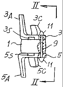
~ Figures 1 and 2 show views of the assembled prosthesis iri elevation,
from the side and rear respectively,
Figure 3 shows a side eview of the prosthesis fitted in position and in
cross-section along the sagittal plane,
Figure 4 shows a rear view along IV-IV in Figure 3,
Figures 5 and 6 show cross-sectional views in plan along V-V and from
beneath along VI-VI in Figure 3 respectively,
Figure 7 shows a perspective view of a component of the prosthesis in
Figure 1;
Figure 8 shows a perspective view of the prosthesis during a stage of
application using divaricator forceps;
Figure 9 shows a lateral view of a further embodiment of the prosthesis
according to the invention;
Figures 10 and 11 show end views according to line X-X and XI-XI of
Fig.9; and
Figure 12 shows a lateral view of the prosthesis of Figures 9-11 fitted
on the spine
Detailed descrilotion of preferred embodiments
With reference to Figures 1, 2 and 3, a prosthesis according to the
invention which has to be inserted between a pair of lumbar vertebrae, for
example L2, L3, comprises an elastic body 1 of broadly cylindrical shape
located between two end plates 3, 5 each of which can be anchored to the
laminar arch of a corresponding vertebra and each of which has a straight
groove 3S, 5S on the surface in contact with body 1 orientated at right
r , r
angles to the sagittal plane along the line X-X (Figure 2). Once fitted the
various parts of the prosthesis are stably secured together through two
lengths of ligament 7, 9 each of which is caused to pass through
corresponding holes 3D, 5D; 3E, 5E; 1 D, 1 E in plates 3, 5 and elastic body
1 respectively, by means of a straight needle which is not shown, and is
secured after being tensioned through rivets 11 fitted to the outer surfaces
of plates 3, 5.
Body 1 is made of elastic material which is flexible in all directions and
CA 02534553 2006-02-02
WO 2004/084743 PCT/IT2004/000148
-5-
may 'be coated with flexible material (e.g. polyester, etc.) suitable for
remaining in contact with human tissues without damaging them or giving
rise to rejection reactions.
With reference to Figures 1, 2, 3, 4 and 5, upper plate 3 has on its
upper surface a central tooth 3A located on the side of the perimeter of the
plate facing the spinal foramen CM and a pair of lateral teeth 3B, 3C
located symmetrically on opposite sides of the sagittal plane along line X-X,
these teeth facing upwards and being slightly inclined with their upper.ends
towards the left (looking at Figure 3). Having this shape, this plate is'
dimensioned so that it can be inserted from beneath against the laminar
arch A2 (Figure 5) of upper vertebra L2 with central tooth 3A located
between the inner central part of laminar arch A2 and spinal foramen CM,
and lateral teeth 3B, 3C each in contact with a lateral outer surface (FB,
FC) of the corresponding lamina forming said laminar arch A2.
With reference to Figures 1, 2, 3, 4 and 6, lower plate 5 has on its
lower surface a central tooth 5A located on the side of the perimeter of the
plate facing the spinal foramen CM and a pair of lateral teeth 5B, 5C
located symmetrically on opposite sides of the sagittal plane along the line
X-X (Figure 5), these teeth facing downwards and being slightly inclined
with their lower ends towards the right (looking at Figure 3). Having this
shape plate 5 is dimensioned in such a way that it can be inserted
downwards against the laminar arch A3 (Figure 6) of lower vertebra L3,
with central tooth 5A located between the inner central part of laminar arch
A3 and the spinal foramen CM, and lateral teeth 5B, 5C each in contact
with a lateral outer surface GB, GC of the corresponding lamina forming
said laminar arch A3.
Once plates 3, 5 have been fitted to corresponding vertebrae L2, L3,
the terminal tips P3, P5 (Figure 8) of divaricator forceps P are inserted into
grooves 3S, 5S and plates 3, 5 together with vertebrae L2, L3 to which they
are ~ fitted are moved apart as far as possible. During this stage the
divaricator forceps also have the function of holding the plates in position.
Thus elastic body 1 can be inserted laterally between plates 3, 5 without
CA 02534553 2006-02-02
WO 2004/084743 PCT/IT2004/000148
-6-
having to' interrupt the supraspinal ligament, and then ligaments 7, 9 can be
r
passed through appropriate holes 3D, 3E; 5D, 5E in plates 3, 5 and 1 D, 1 E
of body 1 and fixed thereto through rivets 11.
Because the dimensions of the vertebrae vary from one individual to
another, and for one individual from one vertebra to another along the
length of the spine, these plates are manufactured in various sizes so as to
cover a wide range of possibilities of use.
Figures 9-12 show a second embodiment of prosthesis according to
the invention. The same reference numbers are used to designate the
same or equivalent parts or elements of the prosthesis.
The elastic body 1 has a slightly different shape and is not cylindrical
but rather has planar lateral surfaces. Such shape can be used also in the
embodiment of the previous figures. The projections 3A, 3B, 3C and 5A, 5B
and 5C are shown in a different shape and dimension by way of example.
The shape of these portions of the prosthesis can depend upon the location
where it has to be applied and/or the morphological characteristics of the
patient which has to receive the prosthesis.
The main difference of the prosthesis of Figures 9-12 with respect to
the previously described embodiment consists in the presence of an
auxiliary ligament 21 which is used to connect the two spinous processes
SP1 and SP2 of the adjacent vertebrae designated L in Figure 12, between
which the prosthesis is inserted. The ligament 21 embraces the two
spinous processes SP1, SP2 and provides an augmentation to the
superspinous ligament and a replacement for the inters~inous ligament,
said auxiliary ligament 21 extending along the same inclined development
of the interspinous ligament, i.e. from the apex of the upper spinous
process to the base of the lower spinous process.
The ligament 21 is anchored to the two plates 3, 5 by means of suitable
connection or anchoring devices. In the example shown in Figures 9-12,
each plate 3, 5 is provided with a pair of opposite hooks designated 3H and
5H respectively, on both sides of the plates. The hooks 3H and 5H are
oppositely oriented: the hooks 3H are opened backwards, i.e. opposite the
CA 02534553 2006-02-02
WO 2004/084743 PCT/IT2004/000148
-7-
spinal foramen, while the , hooks 5H are opened towarcJs said spinal
foramen.
It will be understood that the drawing only shows an example provided
as a practical embodiment of the invention, and the invention may vary in
shape and arrangement without thereby going beyond the scope of the
concept underlying the invention itself. Any reference numbers included in
the appended claims are purely to assist a reading of the claims with
reference to the description, and do not restrict the scope of the protection
represented by the claims.