Language selection

Search

Patent 2534560 Summary

Third-party information liability

Some of the information on this Web page has been provided by external sources. The Government of Canada is not responsible for the accuracy, reliability or currency of the information supplied by external sources. Users wishing to rely upon this information should consult directly with the source of the information. Content provided by external sources is not subject to official languages, privacy and accessibility requirements.

Claims and Abstract availability

Any discrepancies in the text and image of the Claims and Abstract are due to differing posting times. Text of the Claims and Abstract are posted:

  • At the time the application is open to public inspection;
  • At the time of issue of the patent (grant).
(12) Patent: (11) CA 2534560
(54) English Title: ELECTROMAGNETIC WAVE RESISTIVITY TOOL
(54) French Title: OUTIL DE RESISTIVITE A ONDE ELECTROMAGNETIQUE
Status: Granted and Issued
Bibliographic Data
(51) International Patent Classification (IPC):
  • G01V 03/08 (2006.01)
  • G01V 03/12 (2006.01)
  • G01V 03/18 (2006.01)
  • G01V 03/26 (2006.01)
  • G01V 03/30 (2006.01)
(72) Inventors :
  • BESTE, RANDAL T. (United States of America)
  • GOLLA, CHRISTOPHER A. (United States of America)
  • BITTAR, MICHAEL (United States of America)
(73) Owners :
  • HALLIBURTON ENERGY SERVICES, INC.
(71) Applicants :
  • HALLIBURTON ENERGY SERVICES, INC. (United States of America)
(74) Agent: EMERY JAMIESON LLP
(74) Associate agent:
(45) Issued: 2011-11-15
(86) PCT Filing Date: 2004-06-23
(87) Open to Public Inspection: 2005-02-24
Examination requested: 2006-02-02
Availability of licence: N/A
Dedicated to the Public: N/A
(25) Language of filing: English

Patent Cooperation Treaty (PCT): Yes
(86) PCT Filing Number: PCT/US2004/020105
(87) International Publication Number: US2004020105
(85) National Entry: 2006-02-02

(30) Application Priority Data:
Application No. Country/Territory Date
10/634,585 (United States of America) 2003-08-05

Abstracts

English Abstract


A method and system of operating an electromagnetic resistivity tool (20)
wherein at least one transmitting antenna (34) of the tool (20) is selectively
operable at three or more resonant frequencies for better resistivity
profiling of a formation.


French Abstract

L'invention concerne un procédé et un système de fonctionnement d'un outil de résistivité électromagnétique, au moins une antenne de transmission de l'outil pouvant fonctionner sélectivement à au moins trois fréquences de résonance afin de parvenir à un meilleur profil de résistivité d'une formation.

Claims

Note: Claims are shown in the official language in which they were submitted.


CLAIMS
What is claimed is:
1. A logging tool comprising:
a tool body configured for use in a borehole;
a receiving antenna disposed on the tool body; and
a transmitting antenna disposed on the tool body at a spaced apart location
from the
receiving antenna; and
an antenna tuning circuit comprising a relay having a coil, the coil coupled
to a signal
line that carries a signal applied to the transmitting antenna, wherein a
control signal for the
antenna tuning circuit and the signal applied to the transmitting antenna both
propagate along
the signal line, and wherein the antenna tuning circuit is selectively tunable
to obtain a plurality
of resonant frequencies.
2. The logging tool as defined in claim 1 wherein the antenna tuning circuit
selectively
couples capacitance to the transmitting antenna to obtain a plurality of
resonant frequencies.
3. A logging tool comprising:
a tool body configured for use in a borehole;
a receiving antenna disposed on the tool body;
a transmitting antenna disposed on the tool body at a spaced apart location
from the
receiving antenna, wherein the transmitting antenna is selectively operable at
three or more
resonant frequencies for transmitting electromagnetic radiation;
an antenna tuning circuit coupled to the transmitting antenna, the antenna
tuning circuit
operable to selectively couple capacitance to the transmitting antenna to
obtain the three or
more resonant frequencies, the antenna tuning circuit further comprising:
a relay having a coil, the coil coupled to a signal line that carries signals
to the
transmitting antenna;
said relay having a set of contacts selectively coupled by activation of the
coil; and
wherein in a first contact position a capacitance is coupled to the
transmitting antenna,
and
wherein in a second contact position the capacitance is not coupled to the
transmitting
antenna.
9

4. The logging tool as defined in claim 3 wherein the relay couples within a
junction box
proximate to the transmitting antenna.
5. The logging tool as defined in claim 1 wherein the antenna tuning circuit
selectively
couples windings of the transmitting antenna to obtain the plurality of
resonant frequencies.
6. A logging tool comprising:
a tool body configured for use in a borehole;
a receiving antenna disposed on the tool body; and
a transmitting antenna disposed on the tool body at a spaced apart location
from the
receiving antenna, wherein the transmitting antenna is selectively operable at
three or more
resonant frequencies for transmitting electromagnetic radiation;
an antenna tuning circuit coupled to the transmitting antenna, the antenna
tuning circuit
operable to selectively couple windings of the transmitting antenna to obtain
the three or more
resonant frequencies, the antenna tuning circuit further comprising:
a relay having a coil, the coil coupled to a signal line that carries signals
to the
transmitting antenna;
said relay having a set of contacts selectively coupled by activation of the
coil; and
wherein in a first contact position a first set of windings of the
transmitting antenna is
coupled in parallel with a second set of windings of the transmitting antenna;
and
wherein in a second contact position the first set of windings of the
transmitting antenna
is coupled in series with the second set of windings of the transmitting
antenna.
7. The logging tool as defined in claim 6 wherein the relay couples within a
junction box
proximate to the transmitting antenna.
8. The logging tool as defined in claim 1 further comprising:
a plurality of receiving antennas disposed in the tool body;
a plurality of transmitting antennas disposed on the tool body; and
wherein at least one of the plurality of transmitting antennas is selectively
operable at
three or more resonant frequencies.
9. The logging tool as defined in claim 8 further comprising:
10

three receiving antennas disposed on a medial portion of the tool body;
three transmitting antennas disposed on a first end of the tool body; and
three transmitting antennas disposed on a second end of the tool body.
10. The logging tool as defined in claim 9 wherein the tool body further
comprises a tool
body adapted for use within a drillstring.
11. A bottom hole assembly comprising:
a drill bit;
a logging tool coupled to the drill bit, the logging tool comprising:
a tool body;
a plurality of receiving antennas disposed on the tool body; and
a plurality of transmitting antennas disposed on the tool body at a spaced
apart location
from each other and the receiving antennas;
an antenna tuning circuit comprising a relay having a coil, the coil coupled
to and
configured to receive a control signal from a signal line that carries signals
to a first
transmitting antenna, wherein the antenna tuning circuit is selectively
tunable to obtain a
plurality of resonant frequencies.
12. The bottom hole assembly as defined in claim 11, wherein the logging tool
further
comprising a plurality of antenna tuning circuits coupled one each to the
plurality of
transmitting antennas, each antenna tuning circuit each selectively couples
capacitance to its
respective transmitting antenna to achieve a plurality of resonant
frequencies.
13. A bottom hole assembly comprising:
a drill bit;
a logging tool coupled to the drill bit, the logging tool comprising:
a tool body;
a plurality of receiving antennas disposed on the tool body; and
a plurality of transmitting antennas disposed on the tool body at a spaced
apart location
from each other and the receiving antennas;
wherein each transmitting antenna is selectively operable at greater than two
resonant
frequencies for transmitting electromagnetic radiation;
11

a plurality of antenna tuning circuits coupled one each to the plurality of
transmitting
antennas, each antenna tuning circuit each selectively couples capacitance to
its respective
transmitting antenna to achieve the greater than two resonant frequencies,
wherein each
antenna tuning circuit further comprises:
a relay having a coil, the coil coupled to a signal line that carries signals
to a
transmitting antenna;
said relay having a set of contacts selectively coupled by activation of the
coil; and
wherein in a first contact position a capacitance is coupled to the
transmitting antenna,
and
wherein in a second contact position the capacitance is not coupled to the
transmitting
antenna.
14. The bottom hole assembly as defined in claim 13 wherein the relay couples
within a
junction box proximate to its respective transmitting antenna.
15. The bottom hole assembly as defined in claim 11, wherein the logging tool
further
comprising a plurality of antenna tuning circuits coupled one each to the
transmitting antennas,
each antenna tuning circuit operable to selectively couple windings of a
transmitting antenna to
achieve the plurality of resonant frequencies.
16. A bottom hole assembly comprising:
a drill bit;
a logging tool coupled to the drill bit, the logging tool comprising:
a tool body;
a plurality of receiving antennas disposed on the tool body; and
a plurality of transmitting antennas disposed on the tool body at a spaced
apart location
from each other and the receiving antennas, wherein each transmitting antenna
is selectively
operable at greater than two resonant frequencies for transmitting
electromagnetic radiation;
a plurality of antenna tuning circuits coupled one each to the transmitting
antennas,
each antenna tuning circuit operable to selectively couple windings of a
transmitting antenna to
achieve the greater than two resonant frequencies, wherein each antenna tuning
circuit further
comprises:
12

a relay having a coil, the coil coupled to a signal line that carries signals
to a
transmitting antenna, said relay having a set of contacts selectively coupled
by activation of the
coil; and
wherein in a first contact position a first set of windings of the
transmitting antenna is
coupled in parallel with a second set of windings of the transmitting antenna,
and
wherein in a second contact position the first set of windings of the
transmitting antenna
is coupled in series with the second set of windings of the transmitting
antenna.
17. The bottom hole assembly as defined in claim 16 wherein the relay couples
within a
junction box proximate to its respective transmitting antenna.
13

Description

Note: Descriptions are shown in the official language in which they were submitted.

Sorry, the description for patent document number 2534560 was not found. Text is not available for all patent documents. The current dates of coverage are on the Currency of Information  page
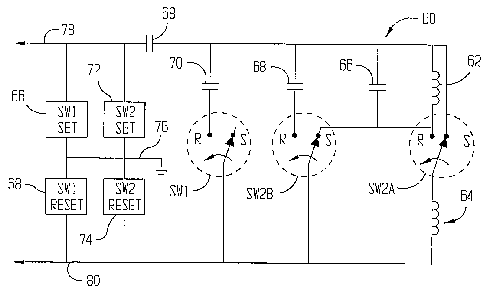
Representative Drawing
A single figure which represents the drawing illustrating the invention.
Administrative Status

2024-08-01:As part of the Next Generation Patents (NGP) transition, the Canadian Patents Database (CPD) now contains a more detailed Event History, which replicates the Event Log of our new back-office solution.

Please note that "Inactive:" events refers to events no longer in use in our new back-office solution.

For a clearer understanding of the status of the application/patent presented on this page, the site Disclaimer , as well as the definitions for Patent , Event History , Maintenance Fee  and Payment History  should be consulted.

Event History

Description Date
Common Representative Appointed 2019-10-30
Grant by Issuance 2011-11-15
Inactive: Cover page published 2011-11-14
Inactive: Final fee received 2011-08-24
Pre-grant 2011-08-24
Notice of Allowance is Issued 2011-08-02
Letter Sent 2011-08-02
Notice of Allowance is Issued 2011-08-02
Inactive: Approved for allowance (AFA) 2011-07-04
Amendment Received - Voluntary Amendment 2010-08-31
Inactive: S.30(2) Rules - Examiner requisition 2010-03-11
Revocation of Agent Requirements Determined Compliant 2009-04-15
Inactive: Office letter 2009-04-15
Appointment of Agent Requirements Determined Compliant 2009-04-15
Revocation of Agent Requirements Determined Compliant 2009-02-24
Inactive: Office letter 2009-02-24
Appointment of Agent Requirements Determined Compliant 2009-02-24
Inactive: Office letter 2009-02-23
Revocation of Agent Request 2009-02-09
Appointment of Agent Request 2009-02-09
Amendment Received - Voluntary Amendment 2008-11-17
Letter Sent 2008-07-25
Reinstatement Requirements Deemed Compliant for All Abandonment Reasons 2008-06-25
Deemed Abandoned - Failure to Respond to Maintenance Fee Notice 2008-06-23
Inactive: S.29 Rules - Examiner requisition 2008-05-29
Inactive: S.30(2) Rules - Examiner requisition 2008-05-29
Inactive: Cover page published 2006-04-04
Inactive: Acknowledgment of national entry - RFE 2006-03-31
Letter Sent 2006-03-31
Application Received - PCT 2006-02-24
National Entry Requirements Determined Compliant 2006-02-02
Request for Examination Requirements Determined Compliant 2006-02-02
All Requirements for Examination Determined Compliant 2006-02-02
National Entry Requirements Determined Compliant 2006-02-02
Application Published (Open to Public Inspection) 2005-02-24

Abandonment History

Abandonment Date Reason Reinstatement Date
2008-06-23

Maintenance Fee

The last payment was received on 2011-04-15

Note : If the full payment has not been received on or before the date indicated, a further fee may be required which may be one of the following

  • the reinstatement fee;
  • the late payment fee; or
  • additional fee to reverse deemed expiry.

Patent fees are adjusted on the 1st of January every year. The amounts above are the current amounts if received by December 31 of the current year.
Please refer to the CIPO Patent Fees web page to see all current fee amounts.

Owners on Record

Note: Records showing the ownership history in alphabetical order.

Current Owners on Record
HALLIBURTON ENERGY SERVICES, INC.
Past Owners on Record
CHRISTOPHER A. GOLLA
MICHAEL BITTAR
RANDAL T. BESTE
Past Owners that do not appear in the "Owners on Record" listing will appear in other documentation within the application.
Documents

To view selected files, please enter reCAPTCHA code :


To view images, click a link in the Document Description column (Temporarily unavailable). To download the documents, select one or more checkboxes in the first column and then click the "Download Selected in PDF format (Zip Archive)" or the "Download Selected as Single PDF" button.

List of published and non-published patent-specific documents on the CPD .

If you have any difficulty accessing content, you can call the Client Service Centre at 1-866-997-1936 or send them an e-mail at CIPO Client Service Centre.

({010=All Documents, 020=As Filed, 030=As Open to Public Inspection, 040=At Issuance, 050=Examination, 060=Incoming Correspondence, 070=Miscellaneous, 080=Outgoing Correspondence, 090=Payment})


Document
Description 
Date
(yyyy-mm-dd) 
Number of pages   Size of Image (KB) 
Description 2006-02-01 8 602
Representative drawing 2006-02-01 1 7
Drawings 2006-02-01 3 42
Claims 2006-02-01 6 302
Abstract 2006-02-01 1 60
Claims 2006-02-02 6 233
Claims 2008-11-16 8 280
Claims 2010-08-30 5 194
Representative drawing 2011-10-11 1 8
Acknowledgement of Request for Examination 2006-03-30 1 190
Notice of National Entry 2006-03-30 1 230
Courtesy - Certificate of registration (related document(s)) 2006-03-30 1 128
Courtesy - Abandonment Letter (Maintenance Fee) 2008-07-24 1 173
Notice of Reinstatement 2008-07-24 1 164
Commissioner's Notice - Application Found Allowable 2011-08-01 1 163
PCT 2006-02-01 6 329
Fees 2007-06-19 1 39
Fees 2008-06-24 1 41
Correspondence 2009-02-08 14 487
Correspondence 2009-02-22 1 13
Correspondence 2009-02-23 1 21
Correspondence 2009-04-14 1 14
Fees 2009-05-19 1 51
Fees 2010-04-12 1 200
Fees 2011-04-14 1 202
Correspondence 2011-08-23 2 69