Language selection

Search

Patent 2535140 Summary

Third-party information liability

Some of the information on this Web page has been provided by external sources. The Government of Canada is not responsible for the accuracy, reliability or currency of the information supplied by external sources. Users wishing to rely upon this information should consult directly with the source of the information. Content provided by external sources is not subject to official languages, privacy and accessibility requirements.

Claims and Abstract availability

Any discrepancies in the text and image of the Claims and Abstract are due to differing posting times. Text of the Claims and Abstract are posted:

  • At the time the application is open to public inspection;
  • At the time of issue of the patent (grant).
(12) Patent: (11) CA 2535140
(54) English Title: AIRFOIL LOCATOR RIB AND METHOD OF POSITIONING AN INSERT IN AN AIRFOIL
(54) French Title: NERVURE DE LOCALISATION DE SURFACE PORTANTE ET METHODE DE POSITIONNEMENT DE PIECE DANS UNE SURFACE PORTANTE
Status: Deemed expired
Bibliographic Data
(51) International Patent Classification (IPC):
  • F01D 5/14 (2006.01)
  • F01D 5/18 (2006.01)
(72) Inventors :
  • SYNNOTT, REMY (Canada)
  • DUROCHER, ERIC (Canada)
(73) Owners :
  • PRATT & WHITNEY CANADA CORP. (Canada)
(71) Applicants :
  • PRATT & WHITNEY CANADA CORP. (Canada)
(74) Agent: NORTON ROSE FULBRIGHT CANADA LLP/S.E.N.C.R.L., S.R.L.
(74) Associate agent:
(45) Issued: 2014-06-03
(22) Filed Date: 2006-02-03
(41) Open to Public Inspection: 2006-08-04
Examination requested: 2011-01-27
Availability of licence: N/A
(25) Language of filing: English

Patent Cooperation Treaty (PCT): No

(30) Application Priority Data:
Application No. Country/Territory Date
11/049,977 United States of America 2005-02-04

Abstracts

English Abstract

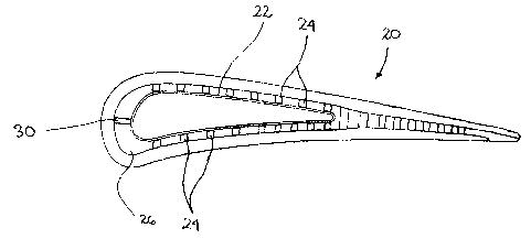
An airfoil for a gas turbine engine, the airfoil comprising a locator rib provided at a bottom of a cavity in the airfoil core, the locator rib having an inclined surface to be engaged by a leading end of the insert during installation thereof in the cavity.


French Abstract

Surface portante pour moteur de turbine à gaz comportant une nervure de localisation au bas d'une cavité située au cur de la surface portante. La nervure de localisation est dotée d'une surface inclinée pouvant être en prise avec une extrémité avant d'une pièce pendant l'installation dans la cavité.

Claims

Note: Claims are shown in the official language in which they were submitted.


5
WHAT IS CLAIMED IS:

1. An airfoil for a gas turbine engine, the airfoil having at least one
internal cooling
passage generally defining at least one cavity in which is located an insert,
the
airfoil comprising a locator rib provided at a bottom of the cavity, the
locator rib
having an inclined surface to be engaged by a leading end of the insert during

positioning thereof in the cavity.
2. The airfoil as defined in claim 1, wherein the locator rib extends in a
substantially chordwise direction.
3. An airfoil for use in a gas turbine engine, the airfoil including
internal walls
defining a cavity for receiving an insert, the cavity having opposite opened
and
bottom ends, the airfoil including a locator rib provided at a junction
between
two walls at the bottom end of the cavity.
4. The airfoil as defined in claim 3, wherein the locator rib extends in a
substantially chordwise direction.
5. A method of positioning an insert in an internally-cooled airfoil, the
method
comprising:
moving the insert into a cavity provided in the airfoil;
bringing a leading side of the insert into engagement with a located rib
inside the
cavity; and
offsetting the insert in a substantially chordwise direction as the leading
end
slides over an inclined surface of the locator rib.
6. The method as defined in claim 5, wherein after the step of offsetting
the insert,
the insert is rigidly attached to the airfoil.

Description

Note: Descriptions are shown in the official language in which they were submitted.


CA 02535140 2006-02-03
AIRFOIL LOCATOR RIB AND METHOD OF POSITIONING
AN INSERT IN AN AIRFOIL
TECHNICAL FIELD
The invention relates generally to the positioning of insert in an airfoil
and, more
particularly, to an improved way of positioning an insert in an airfoil during

manufacturing.
BACKGROUND OF THE ART
Some of the cooled airfoils used in several gas turbine engines are provided
with inserts.
These airfoils may have one or several inserts, each positioned in a
corresponding cavity
provided in the airfoil core. The cavity is generally defined in a cooling
passage of the
airfoil and inserts are generally held by individual standoffs which keep them
away from
the internal walls of the airfoil.
Each insert is brought into the cavity through an opened end and is pushed
therein until its
leading end abuts the bottom of the cavity. It is thereafter welded or
otherwise rigidly
secured to the airfoil core. The conventional positioning feature is a
continuous chamber
or a continuous shoulder around the airfoil, which needs more space underneath
the insert
platform of the vane to correctly position the insert. This adds weight to the
vane.
The positioning of the insert relative to the airfoil core must usually be
very accurate.
Any misalignment of the insert relative to the airfoil core once it is rigidly
secured may
result in that the whole airfoil be considered defective and will not go into
service.
Accordingly, there is a need to provide an airfoil which allows a more
accurate
positioning an insert therein.
SUMMARY OF THE INVENTION
In one aspect, the present invention provides an airfoil for a gas turbine
engine, the airfoil
having at least one internal cooling passage generally defining at least one
cavity in which
is located an insert, the airfoil comprising a locator rib provided at a
bottom of the cavity,
the locator rib having an inclined surface to be engaged by a leading end of
the insert
during positioning thereof in the cavity.

CA 02535140 2006-02-03
2
In a second aspect, the present invention provides an airfoil core for use in
a gas turbine
engine, the airfoil core including internal walls defining a cavity for
receiving an insert,
the cavity having opposite opened and bottom ends, the airfoil core including
a locator rib
provided at a junction between two walls at the bottom end of the cavity.
In a third aspect, the present invention provides a method of positioning an
insert in an
internally-cooled airfoil, the method comprising: moving the insert into a
cavity provided
in the airfoil; bringing a leading side of the insert into engagement with a
located rib
inside the cavity; and offsetting the insert in a substantially chordwise
direction as the
leading end slides over an inclined surface of the locator rib.
Further details of these and other aspects of the present invention will be
apparent from
the detailed description and the appended figures.
DESCRIPTION OF THE DRAWINGS
Fig. 1 schematically shows a generic gas turbine engine to illustrate an
example of a
general environment in which the invention can be used.
Fig. 2 is a semi-schematic cross-sectional view of an airfoil provided with an
insert and a
locator rib in accordance with a preferred embodiment of the present
invention.
Fig. 3 is a schematic side view showing a locator rib and a portion of the
leading end of
the insert shown in Fig. 2.
DETAILED DESCRIPTION
Fig. 1 schematically illustrates an example of a gas turbine engine 10 of a
type preferably
provided for use in subsonic flight, generally comprising in serial flow
communication a
fan 12 through which ambient air is propelled, a multistage compressor 14 for
pressurizing the air, a combustor 16 in which the compressed air is mixed with
fuel and
ignited for generating an annular stream of hot combustion gases, and a
turbine section 18
for extracting energy from the combustion gases. This figure illustrates an
example of the
environment in which the present invention can be used.
Fig. 2 is a semi-schematic representation of a cross section of an airfoil
(20) in which is
positioned one insert (22). The insert (22) is maintained in place on the
sides by standoffs

CA 02535140 2013-09-13
3
(24) projecting from the internal walls of the airfoil (20). These walls
generally define a
cavity (26) which is also a portion of the internal passage of the airfoil
(20) in which
cooling air flows when the gas turbine engine (10) is in operation. Fig. 2
shows that the
core of the airfoil (20) comprises a locator rib (30) located at the bottom of
the cavity
(26). This bottom location is also referred to as the closed end, which end is
opposite to
an opened end through which the insert (22) is inserted during manufacturing.
The
locator rib (30) includes an inclined surface (30A) which can be engaged by
the leading
end (22A) of the insert (22) in the final stages of the positioning of the
insert (22). This
locator rib (30) is generally oriented parallel to the chordwise direction of
the airfoil (20).
It should be noted at this point that the opened end is not necessarily
located at the tip of
the airfoil (20) and it may be located closer to the root. In that case, the
closed (or
bottom) end would be adjacent to the tip of the airfoil (20).
Fig. 3 is an enlarged schematic view of an airfoil core with an example of a
locator rib
(30). The dotted lines represent the position of the insert (22) during its
positioning in the
cavity (26) of the airfoil (20).
When pushing the insert (22) into the cavity (26), and if the insert (22) is
forwardly offset
with reference to its ideal position into the cavity (26), it will contact the
inclined surface
(30A) of the locator rib (30). Pushing the insert (22) further will cause the
insert (22) to
slide along the inclined surface (30A) until it reaches the bottom. This way,
the insert
(22) would not be positioned too close to the leading edge of the airfoil
(20).
The present invention provides a significant weight reducing. Instead of
having a
continuous shoulder or chamfer, only a small thin local rib is required to
locate the insert.
The above description is meant to be exemplary only, and one skilled in the
art will
recognize that changes may be made to the embodiment described without
department
from the scope of the invention disclosed. For example, the locator rib (30)
can have a
shape different than what is shown. More than one locator rib (30) can be used
to
position a same insert (22). Locator ribs (30) can be used on the lateral
sides or at the
rear. The inclined surface (30A) may have another shape than a straight
surface. For
instance, it may be curved or have two or more subsections with different
angles. Still
other modifications which fall within the scope of the present invention will
be apparent

CA 02535140 2006-02-03
4
to those skilled in the art, in light of a review of this disclosure, and such
modifications
are intended to fall within the appended claims.

Representative Drawing
A single figure which represents the drawing illustrating the invention.
Administrative Status

For a clearer understanding of the status of the application/patent presented on this page, the site Disclaimer , as well as the definitions for Patent , Administrative Status , Maintenance Fee  and Payment History  should be consulted.

Administrative Status

Title Date
Forecasted Issue Date 2014-06-03
(22) Filed 2006-02-03
(41) Open to Public Inspection 2006-08-04
Examination Requested 2011-01-27
(45) Issued 2014-06-03
Deemed Expired 2020-02-03

Abandonment History

There is no abandonment history.

Payment History

Fee Type Anniversary Year Due Date Amount Paid Paid Date
Registration of a document - section 124 $100.00 2006-02-03
Application Fee $400.00 2006-02-03
Maintenance Fee - Application - New Act 2 2008-02-04 $100.00 2008-01-30
Maintenance Fee - Application - New Act 3 2009-02-03 $100.00 2009-02-03
Maintenance Fee - Application - New Act 4 2010-02-03 $100.00 2010-02-03
Request for Examination $800.00 2011-01-27
Maintenance Fee - Application - New Act 5 2011-02-03 $200.00 2011-01-31
Maintenance Fee - Application - New Act 6 2012-02-03 $200.00 2012-01-16
Maintenance Fee - Application - New Act 7 2013-02-04 $200.00 2013-02-04
Maintenance Fee - Application - New Act 8 2014-02-03 $200.00 2014-02-03
Final Fee $300.00 2014-03-21
Maintenance Fee - Patent - New Act 9 2015-02-03 $200.00 2015-01-14
Maintenance Fee - Patent - New Act 10 2016-02-03 $250.00 2016-01-21
Maintenance Fee - Patent - New Act 11 2017-02-03 $250.00 2017-01-24
Maintenance Fee - Patent - New Act 12 2018-02-05 $250.00 2018-01-22
Maintenance Fee - Patent - New Act 13 2019-02-04 $250.00 2019-01-25
Owners on Record

Note: Records showing the ownership history in alphabetical order.

Current Owners on Record
PRATT & WHITNEY CANADA CORP.
Past Owners on Record
DUROCHER, ERIC
SYNNOTT, REMY
Past Owners that do not appear in the "Owners on Record" listing will appear in other documentation within the application.
Documents

To view selected files, please enter reCAPTCHA code :


To view images, click a link in the Document Description column. To download the documents, select one or more checkboxes in the first column and then click the "Download Selected in PDF format (Zip Archive)" or the "Download Selected as Single PDF" button.

List of published and non-published patent-specific documents on the CPD .

If you have any difficulty accessing content, you can call the Client Service Centre at 1-866-997-1936 or send them an e-mail at CIPO Client Service Centre.


Document
Description 
Date
(yyyy-mm-dd) 
Number of pages   Size of Image (KB) 
Abstract 2006-02-03 1 9
Description 2006-02-03 4 158
Claims 2006-02-03 1 32
Drawings 2006-02-03 3 36
Representative Drawing 2006-07-11 1 8
Cover Page 2006-07-28 1 32
Drawings 2006-03-23 3 45
Claims 2013-09-13 1 28
Description 2013-09-13 4 151
Cover Page 2014-05-08 1 32
Assignment 2006-02-03 5 180
Prosecution-Amendment 2006-03-23 5 80
Prosecution-Amendment 2011-01-27 2 79
Prosecution-Amendment 2013-09-13 4 154
Prosecution-Amendment 2013-03-18 2 49
Correspondence 2014-03-21 2 68