Note: Descriptions are shown in the official language in which they were submitted.
CA 02535606 2006-02-08
MICROWAVE COOKER
BACKGROUND OF THE INVENTION
s 1. Field of the Invention
The present invention relates to a microwave cooker, and more particularly, to
a microwave cooker capable of effectively preventing a microwave leakage by
enhancing a microwave damping function.
l0 2. Description of the Background Art
A microwave cooker such as a microwave oven, an electric oven, etc. serves
to heat and cook food by scanning microwave generated from a magnetron to
the food.0
is The microwave cooker generally comprises a body having a cooking
chamber, and a door coupled to the body for opening and closing the cooking
chamber. A gap is formed between the body and the door.
When microwave is leaked through the gap between the body and the door,
2o the microwave does harm to a user's body. Therefore, a microwave leakage
from the cooking chamber has to be prevented.
Various methods for preventing the microwave from being leaked from the
cooking chamber through the gap between the body and the door have been
Zs proposed, in which a capacitive seal, a choke seal, or a ferrite rubber is
installed between the body and the door.
The conventional method will be explained in more detail with reference to
FIG. 1.
1
CA 02535606 2006-02-08
FIG. 1 is a graph showing a microwave damping curve of a microwave cooker
in accordance with the conventional art, in which 'A' expressed as decibel
(dB) denotes a damping degree according to a frequency (f) when the cooking
chamber is closed.
In the conventional microwave cooker, a choke seal is formed at the door as a
closed curve that surrounds a circumference of an opening of the cooking
chamber of the body, and has a depth corresponding to 1/4 of a wavelength in
order to serve as a shielding portion of microwave. When the cooking
to chamber of the body is closed by the door, a resonant frequency (f-1 ) of
the
choke seal has the same frequency as a central frequency (f-MGT:
magnetron) of microwave.
When the cooking chamber is opened, a microwave source for supplying
Is microwave is turned off.
However, in the conventional microwave cooker, microwave is drastically
leaked when the door is initially opened.
2o That is, before the microwave source is completely turned off, the door is
opened for a certain section. As the gap between the body and the door is
increased when the cooking chamber is initially opened, an electromagnetic
characteristic is changed. Accordingly, as shown in FIG. 1, the microwave
damping curve is moved to the left side, and thus a damping is performed at a
2s region having an inferior damping function. Therefore, microwave is much
leaked through the gap between the body and the door.
The U.S. Patent No. 6, 538, 241 (hereinafter, will be referred to as the
conventional microwave cooker) discloses a microwave sealing unit for stably
3o performing a damping at a wide frequency region.
2
CA 02535606 2006-02-08
The microwave sealing unit has a double resonant structure having two
sealing cavities, and a resonant frequency of each cavity is positioned at
both
sides of a central frequency of microwave. As each resonant frequency has a
constant gap therebetween, a gap variation of the door is not greatly
s influential thereon and thus a damping function can be stably performed at a
wide frequency region.
However, in the conventional microwave cooker, as each resonant frequency
of the microwave sealing unit is spaced from each other in order to obtain a
io wide bandwidth, a damping function is lowered at a region between each
resonant frequency. Furthermore, since a central frequency of microwave is
positioned at a region having an inferior damping function, an optimum
damping function of the microwave cooker is not implemented.
is The wider a gap between each resonant frequency is (that is, the wider a
bandwidth is), the lower a damping function between each resonant frequency
is. Therefore, when the gap between the body and the door is more than
approximately 4mm, it is difficult to effectively prevent a microwave leakage.
Zo In the conventional microwave cooker, odor, smoke, etc. generated from food
inside the cooking chamber contaminate an inner surface of the door,
especially, the choke seal or the microwave sealing unit, and the
contaminated portion is not easily cleaned.
2s BRIEF DESCRIPTION OF THE INVENTION
Therefore, an object of the present invention is to provide a microwave cooker
capable of enhancing a microwave leakage blocking function and easily
cleaning inside of a body.
3o To achieve these and other advantages and in accordance with the purpose
of the present invention, as embodied and broadly described herein, there is
3
CA 02535606 2006-02-08
provided a microwave cooker, comprising: a body having a cooking chamber
therein for forming an appearance of the microwave cooker; a microwave
source disposed at the body for supplying microwave to the cooking chamber;
a door openably coupled to one side of the body for opening and closing the
s cooking chamber; and a choke seal formed at the door and having a resonant
frequency at a frequency region higher than a central frequency of microwave
when the cooking chamber is closed by the door, for preventing the
microwave from being leaked between the body and the door.
to The choke seal has an LC resonant circuit comprising an inductance (L) and
a
capacitance (C) connected to the inductance in parallel.
The choke seal comprises a cavity having an opening towards a front surface
of the body, a groove formed at a circumferential surface of the door, and a
is control plate extending from a side wall of the groove for partially
covering the
opening.
A difference between the resonant frequency of the choke seal and the central
frequency of the microwave is within 250MHz.
When the door is initially opened, the resonant frequency of the choke seal is
approximately the central frequency of the microwave.
Preferably, a transparent window for viewing inside of the cooking chamber is
2s coupled to the door so as to be disposed between the door and the body, and
has a size corresponding to a size of a front surface of the body.
Preferably, the control plate is formed along a plate surface direction of the
door so as to come in contact with the transparent window.
4
CA 02535606 2006-02-08
The foregoing and other objects, features, aspects and advantages of the
present invention will become more apparent from the following detailed
description of the present invention when taken in conjunction with the
accompanying drawings.
s
BRIEF DESCRIPTION OF THE DRAWINGS
The accompanying drawings, which are included to provide a further
understanding of the invention and are incorporated in and constitute a part
of
this specification, illustrate embodiments of the invention and together with
the
io description serve to explain the principles of the invention.
In the drawings:
FIG. 1 is a graph showing a microwave damping curve of a microwave cooker
in accordance with the conventional art;
is
FIG. 2 is a perspective view showing a structure of a microwave cooker
according to a first embodiment of the present invention;
FIG. 3 is a sectional view taken along line I-I of FIG. 2;
FIG. 4 is an LC resonant circuit diagram applied to a choke seal of the
microwave cooker according to the first embodiment of the present invention;
FIG. 5 is a perspective view showing a structure of the choke seal of the
2s microwave cooker according to the first embodiment of the present
invention;
FIG. 6 is a graph showing a microwave damping curve by the choke seal of
the microwave cooker according to the first embodiment of the present
invention;
5
CA 02535606 2006-02-08
FIGS. 7 and 8 are perspective views showing a structure of a choke seal of a
microwave cooker according to a second embodiment of the present
invention;
s FIG. 9 is an LC resonant circuit diagram applied to the choke seal of FIGS.
7
and 8;
FIGS. 10 and 11 are views for explaining a principle of the choke seal applied
to FIGS. 2 to 9;
io
FIG. 12 is a sectional view showing a structure of a multi-stage choke seal of
a microwave cooker according to a third embodiment of the present invention;
FIG. 13 is a perspective view showing the structure of a multi-stage choke
is seal of a microwave cooker according to the third embodiment of the present
invention;
FIG. 14 is an LC resonant circuit diagram applied to the multi-stage choke
seal of the microwave cooker according to the third embodiment of the
ao present invention;
FIG. 15 is a view showing a microwave damping curve by the multi-stage
choke seal of the microwave cooker according to the third embodiment of the
present invention;
2s
FIG. 16 is a view for comparing the microwave damping curve of FIG. 15 with
a conventional microwave damping curve;
FIG. 17 is an LC resonant circuit diagram applied to a multi-stage choke seal
30 of a microwave cooker according to a fourth embodiment of the present
invention;
s
CA 02535606 2006-02-08
FIG. 18 is a perspective view showing a structure of a multi-stage choke seal
of a microwave cooker according to a fifth embodiment of the present
invention; and
FIG. 19 is a sectional view showing the structure of a multi-stage choke seal
of a microwave cooker according to a fifth embodiment of the present
invention.
io DETAILED DESCRIPTION OF THE INVENTION
Reference will now be made in detail to the preferred embodiments of the
present invention, examples of which are illustrated in the accompanying
drawings.
is Hereinafter, a microwave cooker of the present invention will be explained
in
more detail.
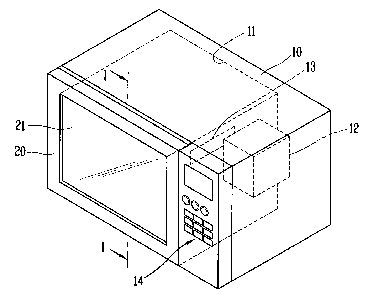
FIG. 2 is a perspective view showing a structure of a microwave cooker
according to a first embodiment of the present invention, FIG. 3 is a
sectional
2o view taken along line I-I of FIG. 2, FIG. 4 is an LC resonant circuit
diagram
applied to a choke seal of the microwave cooker according to the first
embodiment of the present invention, FIG. 5 is a perspective view showing a
structure of the choke seal of the microwave cooker according to the first
embodiment of the present invention, and FIG. 6 is a graph showing a
Zs microwave damping curve by the choke seal of the microwave cooker
according to the first embodiment of the present invention.
As shown in FIGS. 2 to 6, a microwave cooker according to the first
embodiment of the present invention comprises a body 10 having a cooking
3o chamber 11 therein for forming an appearance of the microwave cooker, a
microwave source 12 disposed at the body 10 for supplying microwave to the
CA 02535606 2006-02-08
cooking chamber 11, a door 20 openably coupled to one side of the body 10
for opening and closing the cooking chamber 11, and a choke seal 30 formed
at the door 20 and having a resonant frequency (f-1 ) at a frequency region
higher than a central frequency (f-MGT) of microwave when the cooking
s chamber 11 is closed by the door 20, for preventing the microwave from being
leaked between the body 10 and the door 20.
A microwave supplying unit 13 for supplying microwave generated from the
microwave source 12 to the cooking chamber 11 is disposed at the body 10,
to and an adjustment unit 14 for controlling each kind of component and
selecting a cooking mode is installed at a right side of a front surface of
the
body 10.
The choke seal 30 is an open-type choke seal having an LC resonant circuit
is comprising an inductance (L) and a capacitance (C) connected to the
inductance in parallel at a resonant portion. Also, the choke seal 30 has a
resonant frequency (f-1 ) at a frequency region higher than a central
frequency
(f-MGT) of microwave when the cooking chamber 11 is closed by the door 20.
2o More specifically, the choke seal 30 comprises a groove 31 curvedly-
extending at a circumferential surface of the door 20 and having a single
cavity 32 provided with an opening towards a front surface of the body 10.
The groove 30 has a length corresponding to 1/4 of a wavelength when the
cooking chamber 11 is closed by the door 20.
The resonant frequency (f-1 ) of the choke seal 30 can be varied by
controlling
a structure, a size, etc. of the cavity so that the inductance L and the
capacitance C can be varied.
s
CA 02535606 2006-02-08
The choke seal 30 can further comprise a control plate 33 extending from a
side wall 31 a of the groove 31 for partially covering the opening of the
cavity
32.
s FIGS. 7 and 8 are perspective views showing a structure of a choke seal of a
microwave cooker according to a second embodiment of the present
invention, and FIG. 9 is an LC resonant circuit diagram applied to the choke
seal of FIGS. 7 and 8.
to As shown in FIGS. 7 to 9, in a microwave cooker according to a second
embodiment of the present invention, a choke seal 130 is a short-type choke
seal having an LC resonant circuit comprising an inductance (L) and a
capacitance (C) connected to the inductance in series at a resonant portion.
is In the microwave cooker of the second embodiment, likewise the microwave
cooker of the first embodiment, the choke seal 130 has a resonant frequency
(f-1 ) at a frequency region higher than the central frequency (f-MGT) of
microwave when the cooking chamber 11 is closed by the door 20 as shown
in FIG. 6.
In the microwave cooker according to the second embodiment of the present
invention, the choke seal 130 comprises a groove 131 formed at a
circumferential surface of the door 20 and having a cavity 132 provided with
an opening towards a front surface of the body 10, a control plate 133
2s curvedly-extending from a side wall 131 a of the groove 131 for partially
covering the opening, and slots 134 formed at the control plate 133 with a
certain interval along a progressive direction of microwave in a
circumferential
direction of the door 20.
9
CA 02535606 2006-02-08
The resonant frequency (f-1 ) of the choke seal 130 can be varied by
controlling a structure, a size, etc. of each portion corresponding to the
inductance L and the capacitance C.
s In the microwave cooker according to the first embodiment and the second
embodiment, the central frequency (f-MGT) of microwave is 2450MHz when
the cooking chamber 11 is closed by the door 20. Herein, a difference
between the resonant frequency (f-1 ) of each choke seal 30 and 130 and the
central frequency (f-MGT) of microwave is within a range of 250MHz.
io
That is, when the door 20 is initially opened (that is, when the door 20 is
opened for a certain section before the microwave source 12 is completely
turned off, and thus when a gap is generated between the body 10 and the
door 20), the resonant frequency of the choke seal of the microwave cooker is
is moved within a range of 200MHz. When the difference between the resonant
frequency (f-1 ) of each choke seal 30 and 130 and the central frequency (f-
MGT) of microwave is more than 250MHz, an optimum microwave damping
function provided from each choke seal 30 and 130 is not implemented when
the door 20 is initially opened. Therefore, the difference between the
resonant
2o frequency (f-1 ) of each choke seal 30 and 130 and the central frequency (f-
MGT) of the microwave has to be within 250MHz.
A leakage amount (L) of microwave is increased in proportion to a cube of a
gap G between the body 10 and the door 20 when the gap is less than a
2s wavelength (J~) of microwave. Therefore, when the cooking chamber 11 is
closed by the door 20, the leakage amount (L) from the gap becomes different
according to a tuned position of the resonant frequency (f-1 ) of each choke
seal 30 and 130.
3o As shown in FIGS. 10 and 11, when the cooking chamber 11 is closed by the
door 20, the leakage amount (L) from the gap G between the body 10 and the
CA 02535606 2006-02-08
door 20 becomes different according to a tuned position of the resonant
frequency (f-1 ) of each choke seal 30 and 130 among f-a, f-b, and f-c. In the
present invention, the resonant frequency (f-1 ) of each choke seal 30 and 130
is tuned to be positioned at the f-a region, thereby effectively blocking a
s microwave leakage from a gap (G-1 ) by which the microwave source 12 is
turned off when the door 20 is opened.
When the door 20 is initially opened, the resonant frequency (f-1 ) of each
choke seal 30 and 130 is approximately equal to the central frequency (f-
to MGT) of the microwave in order to implement an optimum damping function.
In the microwave cooker according to the first embodiment and the second
embodiment of the present invention, the central frequency (f-MGT) of
microwave is equal to the resonant frequency (f-1 ) of each choke seal 30 and
is 130 when the door 20 is initially opened. Accordingly, an optimum microwave
damping function provided from the choke seals 30 and 130 is implemented
when the door 20 is initially opened (that is, even if when a gap is generated
between the body 10 and the door 20 before the microwave source 12 is
completely turned off. Also, a microwave leakage blocking function can be
ao enhanced.
As shown in FIG. 8, in the microwave cooker according to the second
embodiment of the present invention, the choke seal 130 further comprises a
slit 135 having a certain depth to be connected to the slot 134 and formed at
Zs the side wall 131 a of the groove 131 from which the control plate 133 is
extending. A microwave damping function can be stably implemented
according to a variation of an incident angle of electromagnetic wave by the
slit 135.
3o A transparent window 21 for viewing inside of the cooking chamber 11 is
formed of glass, plastic, etc., and is coupled to the door 20 according to the
11
CA 02535606 2006-02-08
first embodiment and the second embodiment. The transparent window 21
has a size corresponding to a size of a front surface of the body 10, and is
coupled to the door 20 so as to be disposed between the body 10 and the
door 20.
s
The inner surface of the door 20 is entirely covered with the transparent
window 21, so that an additional choke cover for covering the choke seals 30
and 130 (not shown) is not required.
io Also, the inner surface of the door 20 has an improved design, and the
inner
surface of the door 20, especially, the choke seal 30 that is not easily
cleaned
is prevented from being contaminated by odor, smoke, etc. generated from
the cooking chamber 11. Also, the door 20 can be easily cleaned.
is Furthermore, the control plates 33 and 133 according to the first
embodiment
and the second embodiment are preferably formed along a plate surface
direction of the door 20 so as to come in contact with the transparent window
21.
2o FIG. 12 is a sectional view showing a structure of a multi-stage choke seal
of
a microwave cooker according to a third embodiment of the present invention,
FIG. 13 is a perspective view showing the structure of a multi-stage choke
seal of a microwave cooker according to the third embodiment of the present
invention, FIG. 14 is an LC resonant circuit diagram applied to the multi-
stage
2s choke seal of the microwave cooker according to the third embodiment of the
present invention, FIG. 15 is a view showing a microwave damping curve by
the multi-stage choke seal of the microwave cooker according to the third
embodiment of the present invention, and FIG. 16 is a view for comparing the
microwave damping curve of FIG. 15 with a conventional microwave damping
3o curve.
12
CA 02535606 2006-02-08
In the microwave cooker according to the third embodiment of the present
invention, the same reference numerals were given to the same parts as
those of the microwave cookers according to the first and second
embodiments, and detail explanation thereof will be omitted.
As shown in FIGS. 12 to 17, the microwave cooker according to the third
embodiment comprises a body 10 having a cooking chamber 11 therein for
forming an appearance of the microwave cooker, the cooking chamber 11
having one opened side, a microwave source 12 disposed at the body 10 for
to supplying microwave to the cooking chamber 11, a door 20 rotatably coupled
to a front surface of the body 10 for opening and closing the cooking chamber
11, and a multi-stage choke seal 230 formed at the door 20 and having
different resonant frequencies (f-1, f-2) at a frequency region higher than a
central frequency (f-MGT) of microwave when the cooking chamber 11 is
is closed by the door 20, for preventing the microwave from being leaked from
a
gap between the body 10 and the door 20.
The multi-stage choke seal 230 comprises a first choke seal 230a and a
second choke seal 230b cascaded to be in parallel with each other. The first
2o choke seal 230a and the second choke seal 230b have the same LC resonant
circuit.
That is, the first choke seal 230a and the second choke seal 230b are short
type choke seals, each having an LC resonant circuit comprising an
Zs inductance (L) and a capacitance (C) connected to the inductance at a
resonant portion in series. When the cooking chamber 11 is closed by the
door 20, the first choke seal 230a and the second choke seal 230b have
different resonant frequencies (f-1, f-2) at a frequency region higher than
the
central frequency (f-MGT) of microwave.
13
CA 02535606 2006-02-08
The multi-stage choke seal 230 comprises a groove 231 formed at a
circumferential surface of the door 20 and having a first cavity 232a and a
second cavity 232b separated from each other by a partition wall 236, each
cavity having an opening towards a front surface of the body 10, control
plates
s 233a and 233b curvedly extending from the partition wall 236 and a side wall
231 a of the groove 231 for partially covering each opening, and slots 234a
and 234b formed at the control plates 233a and 233b with a certain interval
along a progressive direction of microwave in a circumferential direction of
the
door 20.
to
The partition wall 236 is fixed to a lower surface of the groove 231 in
parallel
with the side wall 231 a of the groove 231 by a welding or a screw joint. The
resonant frequencies (f-1, f-2) of the first choke seal 230a and the second
choke seal 230b can be varied by controlling a structure, a size, etc. of each
Is portion corresponding to the inductance L and the capacitance C.
In the microwave cooker according to the third embodiment of the present
invention, when the cooking chamber 11 of the body 10 is closed by the door
20, the central frequency (f-MGT) of microwave is 2450 MHz, and a difference
2o between each resonant frequency (f-1, f-2) of the multi-stage choke seal
230
is within 400MHz.
When the difference between each resonant frequency (f-1, f-2) of the multi-
stage choke seal 230 is more than 400MHz, a microwave damping function is
as lowered at each resonant frequency region (f-1, f-2) even if a wide
bandwidth
can be obtained. Therefore, the difference between each resonant frequency
(f-1, f-2) of the multi-stage choke seal 230 is within 400MHz, more
preferably,
within 200MHz.
3o A difference between the resonant frequency (f-1 ) adjacent to the central
frequency (f-MGT) of microwave of each resonant frequency (f-1, f-2) of the
14
CA 02535606 2006-02-08
multi-stage choke seal 230 and the central frequency (f-MGT) of microwave is
within 250MHz.
When the difference between the resonant frequency (f-1 ) adjacent to the
s central frequency (f-MGT) of microwave of each resonant frequency (f-1, f-2)
of the multi-stage choke seal 230 and the central frequency (f-MGT) of
microwave is more than 250MHz, an optimum microwave damping function
provided from the multi-stage choke seal 230 is not implemented when the
door 20 is initially opened. Therefore, the difference between the resonant
to frequency (f-1 ) adjacent to the central frequency (f-MGT) of microwave of
each resonant frequency (f-1, f-2) of the multi-stage choke seal 230 and the
central frequency (f-MGT) of the microwave has to be within 250MHz.
In order to implement an optimum microwave damping function when the door
is 20 is initially opened, one of each resonant frequency (f-1, f-2) of the
multi-
stage choke seal 230 is constructed to be approximately equal to the central
frequency (f-MGT) of the microwave.
In the microwave cooker according to the third embodiment of the present
2o invention, the resonant frequencies (f-1 and f-2) of the multi-stage choke
seal
230 are disposed to be adjacent to each other within an interactive frequency
range. Accordingly, a microwave damping function is increased by at least 20
dB when compared with the conventional damping function, and a microwave
leakage blocking function is enhanced according to a variation of the gap
Zs between the body 10 and the door 20.
Furthermore, in the present invention, each resonant frequency (f-1 and f-2)
of
the multi-stage choke seal 230 are disposed at a frequency region higher than
the central frequency (f-MGT) of microwave, and one of the resonant
3o frequencies (f-1 and f-2) has the same frequency as the central frequency
(f-
MGT) of microwave when the door 20 is initially opened. Therefore, even if a
CA 02535606 2006-02-08
gap between the body 10 and the door 20 is generated before the microwave
source 12 is completely turned off when the door 20 is initially opened, an
optimum damping function provided from the multi-stage choke seal 230 can
be implemented. Also, even if a large gap more than approximately 4mm is
s generated between the body 10 and the door 20, a microwave leakage
blocking is effectively performed.
In the microwave cooker according to the third embodiment of the present
invention, the slits 235a and 235b are respectively formed at the partition
wall
l0 236 from which the control plates 233a and 233b are extending and at the
side wall 231 a of the groove 231. However, the slit can be formed at one side
of the partition wall 236 and the side wall 231 a of the groove 231.
FIG. 17 is an LC resonant circuit diagram applied to a multi-stage choke seal
is of a microwave cooker according to a fourth embodiment of the present
invention.
As shown in FIG. 17, the multi-stage choke seal 230 according to the fourth
embodiment of the present invention can further comprise the slits 235a and
Zo 235b each having a certain depth so as to be connected to each slot 234a
and 234b, and formed at the partition wall 236 from which each control plate
233a and 233b is extending and at the side wall 231 a of the groove 231. A
microwave damping function can be stably implemented according to a
variation of an incident angle of electromagnetic wave by the slits 235a and
2s 235b.
FIG. 18 is a perspective view showing a structure of a multi-stage choke seal
of a microwave cooker according to a fifth embodiment of the present
invention, and FIG. 19 is a sectional view showing the structure of a multi-
3o stage choke seal of a microwave cooker according to a fifth embodiment of
the present invention.
16
CA 02535606 2006-02-08
As shown in FIGS. 18 and 19, in the microwave cooker according to the fifth
embodiment of the present invention, the multi-stage choke seal 230
comprises a groove 231 formed at a circumferential surface of the door 20
s and having a first cavity 232a and a second cavity 232b separated from each
other by a partition wall 236, each cavity having an opening towards a front
surface of the body 10, control plates 233a and 233b curvedly extending from
both side walls 231 a and 231 b of the groove 231 towards the partition wall
236 for partially covering each opening, and slots 234a and 234b formed at
to the control plates 233a and 233b with a certain interval along a
progressive
direction of microwave in a circumferential direction of the door 20.
It is also possible to form the slit 235b having a certain depth so as to be
connected to the slot 234b at the side wall 231 a of the groove 231 from which
is the control plate 233b for covering the opening of the second cavity 232b
is
extending.
In the microwave cooker according to the fifth embodiment of the present
invention, a transparent window 21 for viewing inside of the cooking chamber
20 11 is formed of plastic, etc., and is coupled to the door 20. The
transparent
window 21 has a size corresponding to a size of a front surface of the body
10, and is coupled to the door 20 so as to be disposed between the body 10
and the door 20.
2s The inner surface of the door 20 is entirely covered with the transparent
window 21, so that an additional choke cover (not shown) for covering the
multi-stage choke seal 230 is not required. Also, the inner surface of the
door
20 has an improved design, and the inner surface of the door 20, especially,
the choke seal 30 that is not easily cleaned is prevented from being
3o contaminated by odor, smoke, etc. generated from the cooking chamber 11.
Also, the door 20 can be easily cleaned.
17
CA 02535606 2006-02-08
Each control plate 233a and 233b of the multi-stage choke seal 230 is formed
along a plate surface direction of the door 20 so as to come in contact with
the
transparent window 21.
s
As aforementioned, in the microwave cooker according to the present
invention, a microwave leakage blocking function can be enhanced.
Especially, a microwave leakage blocking function can be stably implemented
to according to a variation of a gap between the body and the door by a
microwave damping function enhanced than the conventional microwave
damping function. Also, even if the gap between the body 10 and the door 20
is generated, an optimum damping function is implemented thereby to
effectively prevent a microwave leakage.
is
Furthermore, the inner surface of the door can have an improved design and
the door can be easily cleaned.
As the present invention may be embodied in several forms without departing
2o from the spirit or essential characteristics thereof, it should also be
understood
that the above-described embodiments are not limited by any of the details of
the foregoing description, unless otherwise specified, but rather should be
construed broadly within its spirit and scope as defined in the appended
claims, and therefore all changes and modifications that fall within the metes
as and bounds of the claims, or equivalence of such metes and bounds are
therefore intended to be embraced by the appended claims.
18