Note: Descriptions are shown in the official language in which they were submitted.
CA 02535772 2009-08-12
MIXING DRUM DRIVE RING
BACKGROUND OF THE INVENTION
The present invention relates generally to the field of composite, heavy-duty,
rotary, concrete mixing drums capable of attachment to vehicles and
components for use with such drums.
Existing concrete mixing trucks or vehicles that are used to transport
concrete
from one site to another generally make use of a metal mixing drum. The
metal mixing drum is mounted to the vehicle and connected at one end to a
drive assembly provided on the vehicle that applies the force needed to rotate
the drum. The drive assembly is made up of a gear box that is generally
powered by the engine of the vehicle. When the gear box is engaged, the
-1-
CA 02535772 2006-02-14
WO 2005/018895 PCT/US2003/025438
engine provides the power or torque needed to rotate the metal mixing drum
around its longitudinal axis. To mix the concrete while the truck is between
sites, and to discharge the concrete when the truck reaches the desired
location, the metal drum generally includes internal vanes or mixing blades.
The vanes are arranged on the inside of the drum in a spiral fashion such that
rotation of the drum in one direction mixes the concrete, and rotation of the
drum in the opposite direction discharges the concrete through an opening
provided on the end of the drum.
Although metal drums have been used for many years, they suffer from a
number of disadvantages. First, the construction of metal drums is a
relatively
labor intensive activity that involves rolling steel sheets into conical
portions
and cylinders and then coupling the different portions together to form the
outer shell of the drum. Once the outer shell of the drum is formed, the
mixing
blades provided on the inside of the drum generally need to be bolted or
welded to the outer shell. Because of the extensive labor required in
performing these and other operations, the cost to construct a metal drum can
be relatively high.
Second, the internal surfaces of a metal drum tend to wear quickly due to the
abrasion on the metal by the concrete, which is increased in the areas where
there are abrupt changes in the inner surface of the drum. Thus, the areas in
which the mixing blades are welded or bolted to the shell of the drum tend to
be areas of increased abrasion that wear rapidly. Moreover, because the
concrete tends to slide, rather than roll, along the inside surface of the
metal
drum, mixing of the concrete tends not to occur along the inside surface of
the
drum.
Third, metal drums can be relatively heavy due to the weight of the metal used
in the construction of the drum. In view of vehicle load limits that place
restrictions on the total weight of the vehicle, the heavier the drum, the
less
concrete can be placed in the drum for transportation to another site. Thus, a
truck having a heavier drum may not be able to carry as much payload as a
-2-
CA 02535772 2006-02-14
WO 2005/018895 PCT/US2003/025438
similar truck that has a lighter drum, increasing the long-term operating
costs
of the truck.
Finally, metal drums tend to absorb and retain heat from the environment and
from the exothermic reaction that takes place between the different
substances in the concrete. This additional heat retained by the drum tends to
decrease the time during which the concrete begins to set. Thus, the distance
over which concrete can be moved within mixing trucks that have metal drums
is limited.
Attempts have been made to improve the conventional mixing drum. For
example, it is known to coat the inside of a metal drum, including the mixing
blades, with a resilient wear resistant material. However, while this may
improve the wear and mixing characteristics of the traditional metal drum, the
coating adds to both the weight of the drum and the costs of manufacturing
the drum. Moreover, while reinforced plastic mixing blades have been used in
such coated medal drums, the additional step of attaching the mixing blade to
the drum requires an additional manufacturing step. It is also know to form
the
mixing drum from a reinforced plastics material and to then attach the mixing
blades to the plastics material. However, like the metal drum, the additional
step of attaching the mixing blades adds to the cost of manufacturing the
drum.
Due to the differences in the material properties and characteristics of a
metal
drum and a polymer or composite drum, some devices and components
employed in conventional drums will not work effectively with a composite
drum. For example, components such as hatches and drive ring assemblies
traditionally used with concrete drums are not compatible with a plastic or
composite drum. Moreover, such conventional components tend to be
relatively heavy and expensive to manufacture.
Accordingly, it would be advantageous to provide a mixing drum that is cost
effective to make and use. It would further be advantageous to provide a
-3-
CA 02535772 2009-08-12
mixing drum that is not as labor intensive to produce. It also would be
advantageous to provide a mixing drum that is substantially resilient to wear.
It would further be advantageous to provide a mixing drum that is capable of
withstanding normal loads but is lighter than conventional metal drums.
Moreover, it would be advantageous to provide a mixing drum that is not as
susceptible to temperature increases as a conventional metal drum.
Additionally, it would be advantageous to provide a mixing drum that
effectively mixes concrete along the inside surface of the drum. It would also
be advantageous to provide components for plastic or composite mixing
drums that are suited to the particular properties of the plastic or composite
drum and that are lighter and less costly than conventional components for
metal mixing drums. It would still further be advantageous to provide a mixing
drum that includes any one or more of these or other advantageous features.
SUMMARY OF THE INVENTION
In one aspect, the present invention provides a concrete mixing truck for
transporting concrete from one location to another, the truck having a chassis
with a frame, a first power source coupled to the frame, wheels coupled to the
frame and a first drivetrain coupling the first power source and the wheels. A
second drivetrain is coupled to a second power source and a composite
mixing drum is coupled to the frame and to the second drivetrain. The drum
has a wall defining a first end of the drum and a second end of the drum. A
drive ring is coupled to the first end of the drum and comprises a hub
operatively coupled to the second drivetrain and a plurality of extensions
extending outwardly from the hub into the wall of the drum, at least one of
the
extensions including an aperture extending therethrough. Rotation of the hub
by the second drivetrain causes rotation of the drum.
-4-
CA 02535772 2009-08-12
The invention also provides, individually, a composite mixing drum and a drive
ring for coupling to such a drum. A method of coupling a drive ring to a wall
of
a composite mixing drum is also defined herein.
BRIEF DESCRIPTION OF THE DRAWINGS
FIGURE 1 is a side view of a concrete mixing vehicle having a mixing drum
according to one exemplary embodiment.
FIGURE 2 is a perspective view of the mixing drum illustrated in FIGURE 1.
FIGURE 3 is a cross-section view of the mixing drum illustrated in FIGURE 1
taken along line 3-3.
FIGURE 4 is a partial cross-sectional view of the mixing drum illustrated in
FIGURE 1.
FIGURE 5 is a fragmentary perspective view of a support member and a
spacer according to an exemplary embodiment.
FIGURE 6 is a cross-sectional view of a support member and a spacer shown
within a mold.
-4a-
CA 02535772 2006-02-14
WO 2005/018895 PCT/US2003/025438
FIGURE 7 is an enlarged cross-sectional view of a portion of the mixing drum
illustrated in FIGURE 4.
FIGURE 8 is an exploded perspective view of a hatch cover assembly according
to one exemplary embodiment.
FIGURE 9 is a cross-sectional view of the hatch cover assembly illustrated in
FIGURE 8.
FIGURE 10 is an exploded perspective view of a hatch cover assembly
according to another exemplary embodiment.
FIGURE 11 is a cross-sectional view of the hatch cover assembly illustrated in
FIGURE 10.
FIGURE 12 is a perspective view of a drive ring according to an one exemplary
embodiment.
FIGURE 13 is a top view of the drive ring illustrated in FIGURE 12.
FIGURE 14 is a partial cross-sectional view of the drive ring illustrated in
FIGURE 12.
FIGURE 15 is a top view of a drive ring according to another exemplary
embodiment.
DETAILED DESCRIPTION OF THE EXEMPLARY EMBODIMENTS
FIGURE 1 is an illustration of a concrete mixing truck 10, which includes a
chassis 12, a cab region 14, a mixing drum 16, and a mixing drum drivetrain
18. Chassis 12 includes a frame 20, a power source 22, a drivetrain 24, and
wheels 26. Frame 20 provides mixing truck 10 with the structural support
and rigidity needed to carry heavy loads of concrete. Power source 22 is
coupled to frame 20 and generally comprises a source of rotational mechanical
energy which is derived from a stored energy source. Examples include, but
-5-
CA 02535772 2006-02-14
WO 2005/018895 PCT/US2003/025438
are not limited to, an internal combustion gas-powered engine, a diesel
engine,
turbines, fuel cell driven motors, an electric motor or any other type of
motor
capable of providing mechanical energy.
For purposes of this disclosure, the term "coupled" means the joining of two
members directly or indirectly to one another. Such joining may be stationary
in nature or moveable in nature. Such joining may be achieved with the two
members or the two members and any additional intermediate members being
integrally formed as a single unitary body with one another or with the two
members or the two members and any additional intermediate members being
attached to one another. Such joining may be permanent in nature or
alternatively may be removable or releasable in nature.
Drivetrain 24 is coupled between power source 22 and wheels 26 and
transfers power (or movement) from power source 22 to wheels 26 to propel
truck 10 in a forward or rearward direction. Drivetrain 24 includes a
transmission 25 and a wheel end reduction unit 27. Both transmission 25 and
wheel end reduction unit 27 utilize a series or set of gears to adjust the
torque
transmitted by power source 22 to wheels 26. One example of a wheel end
reduction unit is described in copending U.S. Patent Application Serial No.
09/635,579, filed on August 9, 2000, by Brian K. Anderson entitled NON-
CONTACT SPRING GUIDE, the full disclosure of which is hereby incorporated
by reference.
Cab region 14 is coupled to chassis 12 and includes an enclosed area from
which an operator of truck 10 drives and controls at least some of the various
functions of truck 10.
Drive assembly or drivetrain 18 is operatively coupled to power source 22 and
mixing drum 16 and uses the power or movement from power source 22 to
provide a rotational force or torque to mixing drum 16. According to an
alternative embodiment, the drivetrain may be powered by a source other than
power source 22 that is provided on truck 10.
-6-
CA 02535772 2006-02-14
WO 2005/018895 PCT/US2003/025438
Referring now to FIGURE 3, mixing drum 16 includes a barrel 33, projections
32, ramps 40, a hatch cover assembly 37 or 200, a drive ring 39, and a roller
ring 35. Barrel 33 is a generally teardrop- or pear-shaped container that has
an
opening 28 on one end (the smaller end) and a drive ring 39 (described below)
coupled to the other larger end 30 of barrel 33. Barrel 33 includes an inner
drum layer 34 and an outer drum layer 36. Inner drum layer 34 is made up of
two spiral-shaped sections 41 and 43 that are "screwed" or mated together.
Each of sections 41 and 43 is a substantially flat panel that is formed in the
shape of a spiral around an axis that becomes a central axis 31 of barrel 33
when sections 41 and 43 are completely assembled. Each of sections 41 and
43 has a width W that extends substantially parallel to axis 31 of barrel 33
(or
that extends generally along the length of the central axis) and a length that
substantially circumscribes or encircles the axis 31. According to one
exemplary embodiment, the width of each section varies along the length of
each section, for example from between approximately 6 inches and 36
inches. Each of the sections 41 and 43 has a first edge 47 that extends the
length of the section and a second edge 49 that extends the length of the
section. Each of sections 41 and 43 is spiraled around the axis 31 of barrel
33
such that there is a gap between the first edge 47 of the section and the
second edge 49 of the same section. This gap provides the space that will be
filled by the other section when it is mated or screwed to the first section.
Accordingly, when the sections 41 and 43 are assembled together to form.
inner drum layer 34, edge 47 of section 41 will abut edge 49 of section 43 and
edge 49 of section 41 will abut edge 47 of section 43. A seam 58 is formed
where the edges of sections 41 and 43 abut one another.
Once the two sections of the inner drum layer 34 have been assembled, outer
drum layer 36 is formed as a continuous layer around the outer surface of
inner
drum layer 34. Accordingly, outer drum layer 34 extends continuously from
one end of the barrel to the other and spans the seams between sections 41
and 43. Outer drum layer 36 is a structural layer that is made from a fiber
reinforced composite material applied by winding resin coated fibers around
the
-7-
CA 02535772 2006-02-14
WO 2005/018895 PCT/US2003/025438
outer surface of inner drum layer 34. According to one embodiment, the resin
is Hetron 942, available from Ashland Chemical, in Dublin, Ohio, and the
fibers
are fiberglass, preferably 2400 Tex E Glass (approximately 206 yards/lb).
According to one embodiment, the angle at which the fibers are wound around
the drum at the major axis (the location at which barrel 33 has the greatest
diameter) is approximately 10.5 degrees relative to axis 31 of the barrel 33.
During the winding process, the resin coated fibers are wrapped generally from
one end of the drum to the other. According to one embodiment, the fibers
are provide in a ribbon or bundle that is approximately 250 millimeter wide
and
includes 64 strands. The ribbon of fibers is wrapped around the drum such
that there is an approximately 50% overlap between each pass of the ribbon.
The wrapping the fibers from end to end, helps to provide drum 16 with the
structural support to .withstand the various forces that are applied to drum
16
in a variety of different directions.
According to an exemplary embodiment, projections 32 and ramps 40 are
integrally formed a single unitary body with sections 41 and 43. Each of
sections 41 and 43, and the corresponding projections and ramps, are formed
through an injection molding process from polyurethane, and outer drum layer
36 is made using fiberglass fibers coated with a resin. According to other
alternative embodiments, the inner drum layer and/or the outer drum layer may
be made from any one or. more of a variety of different materials including
but
not limited to polymers, elastomers, rubbers, ceramics, metals, composites,
etc. According to still other alternative embodiments, other processes or
components may be used to construct the drum. For example, according to
various alternative embodiments, the inner drum layer may be formed as a
single unitary body, or from any number of separate pieces, components, or
sections. According to other alternative embodiments, the inner drum layer, or
any of sections making up part of the inner drum layer, may be made using
other methods or techniques. According to still other alternative embodiments,
the outer drum layer may be applied over the inner drum layer using any one or
more of a number of different methods or techniques.
-8-
CA 02535772 2006-02-14
WO 2005/018895 PCT/US2003/025438
Referring still to FIGURE 3, projections 32a and 32b are coupled to sections
41
and 43, respectively, and extend inwardly toward central axis 31 of barrel 33
and along the length of the respective section. Accordingly, two substantially
identical projections 32a and 32b are coupled to inner drum layer 34 and
spiral
around the inner surface of inner drum layer 34 in the shape of an archimedian
spiral. In one embodiment, projection 32a and 32b extend from an axial end of
barrel 33 across an arial midpoint of barrel 33. Projections 32a and 32b are
circumferentially spaced apart around axis 31 by approximately 180 degrees.
Because projections 32a and 32b are substantially identical, further
references
to the projections will simply refer to "projection 32" when discussing either
(or both of) projection 32a or 32b.
A projection and one or more ramps are coupled to each section of inner drum
layer 34. Because the projection and ramp(s) that are coupled to each section
include substantially identical features and elements, where appropriate, the
projection and ramps that are coupled to one section will be described, it
being
understood that the projection and ramps of the other section are
substantially
identical. FIGURE 4 illustrates projection 32 and ramps 40a and 40b, which
are coupled to section 41, in greater detail.
Projection 32 (e.g., fin, blade, vane, screw, formation, etc.) includes a base
portion 42, an intermediate portion 44, and an end portion 46. Base portion
42 extends inwardly from section 41 toward the axis of drum 16 and serves as
a transitional area between section 41 and intermediate portion 44 of
projection 32. Such a transitional area is beneficial in that it tends to
reduce
stress concentrations in base portion 42 that may result from the application
of
force to projections 32 by the concrete. The reduction of the stress
concentrations tends to reduce the likelihood that projection 32 will fail due
to
fatigue. To provide the transitional area, base portion 42 is radiused or
tapered
on each side of projection 32 to provide a gradual transition from section 41
to
intermediate portion 44. To minimize any unwanted accumulation of set
concrete, the radius is preferably greater than 10 millimeters. According to
-9-
CA 02535772 2006-02-14
WO 2005/018895 PCT/US2003/025438
one exemplary embodiment, the radius is approximately 50 millimeters. .
According to another embodiment, the radius begins on each side of projection
32 proximate section 41 approximately three inches from the centerline of
projection 32 and ends approximately five inches up the height H of projection
32, proximate intermediate region 44 of projection 32. Because drum 16
rotates, the orientation of any particular section of projection 32 constantly
changes. Accordingly, to simplify the description of projection 32, the term
"height," when used in reference to projection 32, will refer to the distance
projection 32 extends inwardly toward the center axis of drum 16, measured
from the center of base portion proximate section 41 to the tip of end portion
46. It should be noted, however, that the height of projection 32 changes
along the length of projection 32. Consequently, the locations at which the
radius or taper begins and/or ends, or the distance over which the radius or
taper extends, may vary depending on the height and/or location of any
particular portion of the projection. According to various alternative
embodiments, the radius of the base region may be constant or it may vary.
According to other alternative embodiments, the transition between the section
and the intermediate portion of the projection may be beveled or may take the
form of some other gradual transition. Moreover, the locations at which the
transition or taper may begin or end may vary depending on the material used,
the thickness of the inner drum wall, the height of the projection, the loads
that will be placed on the projection, the location of a particular portion of
the
projection within the drum, and a variety of other factors.
According to any exemplary embodiment, the characteristics of the taper
should be such that the projection is allowed to at least partially flex under
the
loads applied by the concrete. However, if the taper is such that it allows
the
projection to flex too much, the projection may quickly fatigue. One the other
hand, if the taper is such that it does not allow the projection to flex
enough,
the force of the concrete on the projection may pry on inner drum layer 34 and
potentially tear inner drum layer away from outer drum layer 36.
-10-
CA 02535772 2006-02-14
WO 2005/018895 PCT/US2003/025438
Intermediate portion 44 of projection 32 extends between base portion 42 and
end portion 46. According to one embodiment, intermediate portion 44 has a
thickness of approximately six millimeters and is designed to flex when force
from the concrete is applied thereto.
End portion 46 of projection 32 extends from intermediate portion 44 toward
the axis of drum 16 and includes a support member 48 and spacers 50. The
thickness of end portion 46 is generally greater than the thickness of
intermediate portion 44. Depending on where along the length of projection 32
a particular section of end portion 46 is provided, the added thickness of end
portion 46 may be centered over intermediate portion 44 or offset to one side
or the other. In some areas along the length of projection 32, end portion 46
is provided on only one side of intermediate portion 44 (e.g., the side
closest
to opening 28 or the side closest to end 30). In such a configuration, end
portion 46 acts as a lip or flange that extends over one side of intermediate
portion 44 and serves to improve the ability of projection 32 to move or mix
concrete that comes into contact with the side of intermediate portion 44 over
which end portion 46 extends. Due to the increased thickness of end portion
46 in relation to intermediate portion 44, end portion 46 includes a
transitional
region 45 that provides a gradual transition from intermediate portion 44 to
end portion 46. According to an exemplary embodiment, the transitional
region is radiused. According to alternative embodiments, the transitional
region may be beveled or tapered. To minimize any wear or accumulation that
may occur as a result of concrete passing over end portion 46, projection 32
terminates in a rounded edge 52.
According to various alternative embodiments, each of the base region, the
intermediate region, and the end region may be different sizes, shapes,
thicknesses, lengths, etc. depending on the particular situation or
circumstances in which the drum will be used.
FIGURES 4-6 illustrate support member 48 in greater detail. As shown in
FIGURES 4-6, support member or torsion bar 48 is an elongated circular rod or
-11-
CA 02535772 2006-02-14
WO 2005/018895 PCT/US2003/025438
beam that is embedded within end portion 46 of projection 32 to provide
structural support to projection 32. Torsion bar 48 has a shape that
corresponds to the spiral-like shape of projection 32 and extends the entire
length of projection 32. The ends of bar 48 have flared fibers that are
embedded in inner drum layer 34. Torsion bar 48 serves to substantially
restrict the ability of end portion 46 of projection 32 to flex when a load is
applied to projection 32 by the concrete, and thereby prevents projection 32
from essentially being folded or bent over by the concrete. Although
sufficiently rigid to support projection 32, torsion bar 48 is preferably
torsionally flexible. The torsional flexibility of torsion bar 48 allows it to
withstand torsional loads that result from some deflection of end portion 46
of
projection 32. According to one exemplary embodiment, support, member 48
is a composite material that is made primarily of carbon or graphite fibers
and a
urethane-based resin. According to one exemplary embodiment, the ratio of
carbon fibers to the urethane-base resin is 11 pounds of carbon fiber to 9
pounds of urethane-based resin. One example of such a urethane-based resin
is Erapol EXP 02-320, available from Era Polymers Pty Ltd in Australia.
According to alternative embodiments, the support member may be made from
any combination of materials that allows the support member to provide the
desired structural support yet at the same time allows the torsion bar to
withstand the torsional loads that may be applied to the torsion bar. For
example, the torsion bar may be made from one or more of fiberglass fibers
and ester-based resins. According to other alternative embodiments, the size
and shape of the of the support member may vary depending on the particular
circumstances in which the support member will be used.
According to an exemplary embodiment, support member 48 is made through a
pulltrusion process. The pulltrustion process includes the steps of collecting
a
bundle of fibers, passing the fibers through a bath of resin, and then pulling
the
resin coated fibers through a tube. The support member 48 is then wrapped
around an appropriately shaped mandrel and allowed to cure to give support
member 48 the desired shape . The fibers are pulled through the tube by a
-12-
CA 02535772 2006-02-14
WO 2005/018895 PCT/US2003/025438
cable of a winch that is passed through the tube and coupled to the fibers. To
facilitate the coupling of the cable to the fibers, the fibers are doubled
over and
the cable is attached to the loop created by the doubled over fibers. The
winch pulls the cable back through the tube, which, in turn, pulls the fibers
through the tube. According to one exemplary embodiment, the urethane-
based resin through which the fibers are passed before entering the tube is
injected into the tube at various points along the length of the tube as the
fibers are being pulled through the tube. According to alternative
embodiments, the support member may be made by any one or more of a
variety of different processes.
According to one exemplary embodiment, projection 32 and ramps 40 are
integrally formed with each of sections 41 and 43 as a single unitary body and
are made along with sections 41 and 43. As described above, each of
sections 41 and 43, and the corresponding projection 32 and ramps 40, are
preferably made through an injection molding process during which an
elastomer is injected between molds. In order to embed support member 48
within end portion 46 of projection 32, support member 48 is placed in a mold
54 (a portion of which is shown in FIGURE 6) that defines the shape of
projection 32 prior to the injection of the elastomer. To keep support member
48 in the proper location within the mold during the injection process,
spacers,
shown as helical springs 50, are wrapped around the circumference of support
member 48 and spaced intermittently along the length of support member 48.
Each spring 50 is retained around the circumference of support member 48 by
connecting one end of spring 50 to the other. When support member 48 and
springs 50 are placed in the mold prior to the injection process, springs 50
contact an inside surface of mold 54 and thereby retain support member 48 in
the proper location within mold 54.
When the elastomer is injected into the molds, the elastomer flows through
spring 50 and surrounds (e.g., embodies, encapsulates, etc.) each of its
coils.
As a result, there is a continuous flow of the elastomer through spring 50,
-13-
CA 02535772 2006-02-14
WO 2005/018895 PCT/US2003/025438
such that if the elastomer does not securely bond to the coils of spring 50,
the
areas along projection 32 where springs 50 are placed are not significantly
weaker than the areas along projection 32 where there are no spring spacers
50. According to various alternative embodiments, other materials and
structures may be used as spacers. For example, the spacer may be made
from any one or more of a variety of materials including polyermers,
elastomers, metals, ceramics, wood, etc. The spacer may also be any one of a
variety of different shapes and configurations, including but not limited to,
circular, rectangular, triangular, or any other shape. Moreover, the spacer
may
not substantially surround the support member, but rather may include one or
more members that are provided intermittently around the periphery of the
support member. According to other alternative embodiments, the spacer may
be a flat disc or a cylinder having an outside diameter that contacts the
inside
surface of the mold and an aperture through which the support member
passes. The flat disc or cylinder also may include a plurality of apertures
extending therethrough to allow for the continuous flow of the injected
elastomer through at least some areas of the disc.
FIGURES 4 and 7 illustrate ramps 40 in more detail. As shown in FIGURES 4
and 7, ramps 40a, 40b, 40c, and 40d are raised, ramp-like structures that
extend inwardly from section 41 toward center .axis 31 of barrel 33. Ramp
40a includes a surface 60a that extends toward center axis 31 as it
approaches seam 58a, which is formed where edge 47 of section 41 abuts
edge 49 of section 43. Ramp 40a also includes a surface 62a that extends
from the end of surface 60a back toward section 41 and that terminates at
seam 58a. Ramps 40b, 40c, and 40d include similar surfaces (which are
labeled with the same reference numbers as ramp 40a followed by the
respective letter designation corresponding to each ramp). Preferably, the
ramps are provided in pairs, with one ramp on each side of a seam such that
the seam is located within a channel or valley that is created by the ramps.
Thus, ramp 40a cooperates with ramp 40c to provide a valley or channel 64a
that is defined by surface 62a of ramp 40a and surface 62c of ramp 40c.
-14-
CA 02535772 2006-02-14
WO 2005/018895 PCT/US2003/025438
Seam 58a lies at the base of channel 64a. Similarly, ramp 40b cooperates
with ramp 40d to provide a valley or channel 64b that is defined by surface
62b of ramp 40b and surface 62d of ramp 40d. Seam 58b lies at the base of
channel 64b. According to an exemplary embodiment, the peak of each ramp
extends inwardly from section 41 toward the axis of the drum a distance P,
which is approximately six millimeters.
According to various alternative and exemplary embodiments, the proportions
and dimensions of the ramps may vary. For example, the distance of
corresponding ramps from one another, the angle at which the ramp surfaces
extend away from or toward the center axis of the barrel, the location along
the wall of the barrel at which the ramp begins to extend toward the center
axis of the barrel, the height of the peak of the ramps, etc. may all be
varied to
suit any particular application. According to another alternative embodiment,
only one ramp may be provided proximate each seam.
To facilitate the assembly of sections 41 and 43, sections 41 and 43 of inner
drum layer 34 are substantially free of any structures that would help to
align
sections 41 and 43 with one another. While such structures would help align
sections 41 and 43 and possibly reduce any seams that may be provided in
inner drum layer 34, such structures may tend to complicate the assembly of
sections 41 and 43. In the absence of such alignment structures, sections 41
and 43 are assembled such that one section simply abuts the other section.
While allowing the sections to abut one another tends to facilitate the
assembly of sections 41 and 43, the absence of any alignment structures on
sections 41 and 43 may mean that the edges of sections 41 and 43 may not
always be perfectly aligned with one another. As a result, inner drum layer 34
may include seams 58a and 58b. In the absence of ramps 40a, 40b, 40c, and
40d, seams 58a and 58b may tend to create high wear points due to the
aggregate that would build up in and around the seam. Ramps 40a, 40b, 40c,
and 40d help to minimize this wear by directing the concrete away from seams
58a and 58b. To further minimize any wear that may occur in the area around
-15-
CA 02535772 2006-02-14
WO 2005/018895 PCT/US2003/025438
seams 58a and 58b, each of channels 64a and 64b is filled with a filler
material 66. When channels 64a and 64b are filled with filler material 66, the
concrete within drum 16 passes over the ramps 40a, 40b, 40c, and 40d and
over the filler material. Accordingly, any wear that may occur proximate the
seams 58a and 58b is reduced. According to an exemplary embodiment, the
filler material is the same general material from which the inner drum layer
is
made. According to various alternative embodiments, the filler material may be
any one or more of a variety of different materials, including but not limited
to
polymers, elastomers, silicones, etc.
Referring now to FIGURES 8 and 9, a hatch cover assembly 37 is shown
according to one exemplary embodiment. Hatch cover assembly 37 includes a
hatch cover 68 and a plate 72 and is intended to close and seal an opening or
aperture 67 that is provided in barrel 33. According to one embodiment;
opening 67 is generally oval-shaped, having a major axis of approximately 19.5
inches and a minor axis of approximately 15.5 inches. According to other
alternative embodiments, the opening may have any one of a variety of
different shapes and'have a variety of different sizes. According to one
exemplary embodiment, opening 67 has a size that is sufficient to allow a
person to pass through the opening to gain access to the inside of barrel 33.
The opening 67 may size to allow the concrete with barrel 33 to drain out
through the opening 67. Hatch cover 68 (e.g., cover, door, closure, plate,
etc.) is a generally circular or oval-shaped flat panel that includes an outer
surface 74 and an inner surface 76. For purposes of describing the hatch
cover assemblies, references to an "inner" or "inside" surface refer to the
surface that is closest to or that faces the inside of drum 16, while
references
to an "outer" or "outside" surface refer to the surface that is closest to or
faces the outside of drum 16. A recess 78 that extends into outer surface 74
of hatch cover 68 for approximately half the thickness of hatch cover 68 is
provided on the outer periphery of hatch cover 68. Recess 78 has the effect
of creating a flange or shoulder 80, which extends around the periphery of
hatch cover 68 proximate inner surface 76, and a raised region 81, which
-16-
CA 02535772 2006-02-14
WO 2005/018895 PCT/US2003/025438
extends from the center of hatch cover 68, each having a thickness equal to
approximately half the thickness of hatch cover 68. Hatch cover 68 also
includes coupling members (e.g., receiving members, fasteners, inserts, etc.)
shown as threaded nuts 82 that are embedded into outer surface 74 of raised
region 81. Nuts 82 are arranged in a pattern such that when the coupling
members (e.g. posts, beams, pins, etc.), shown as bolts or studs 84, are
coupled to nuts 82, bolts 84 extend through plate 72 and through opening 67.
Plate 72 (e.g., panel, cover, bolt plate, retaining ring, etc.) is a generally
circular or oval-shaped disc that has an outside periphery that extends beyond
(or overlaps) the periphery of opening 67 in drum 16. Plate 72 includes a
plurality of apertures 102 that are configured to allow bolts 84 to pass
through
plate 72 and couple to nuts 82 in hatch cover 68. According to an exemplary
embodiment, plate 72 includes an opening 100 that extends through the center
of plate 72. According to an alternative embodiment, the plate may not
include opening 100, but rather may be a substantially solid disc.
According to an exemplary embodiment, a panel 70 that substantially
surrounds opening 67 is incorporated into drum 16. Panel 70 (e.g., plate,
surround, support panel, etc.) is a generally circular or oval-shaped panel
that is
intended to reinforce and structurally support drum 16 in the areas
surrounding
opening 67. Panel 70 has an outer periphery that extends beyond (or overlaps)
the outer periphery of hatch cover 68 as well as an opening 86 that is
configured to receive hatch cover 68. Panel 70 includes an outer surface 88
and an inner surface 90. An annular recess 92, provided around opening 86
on inner surface 90, is configured to receive shoulder 80 of hatch cover 68.
The depth of recess 92 (i.e., the distance the recess extends into panel 70)
is
approximately equal to the thickness of shoulder 80, which allows inner
surface 76 of hatch cover 68 to be substantially flush with inner surface 90
of
panel 70. By making inner surface 76 flush with the inside surface of inner
drum layer 34, the inner surface of inner drum layer 34 remains generally
-17-
CA 02535772 2006-02-14
WO 2005/018895 PCT/US2003/025438
smooth, which helps to avoid the build up of aggregate that tends to occur
where there are abrupt changes in the inner surface of a drum.
According to an exemplary embodiment, panel 70 is made separately from
sections 41 and 43 of inner drum layer 34 and is incorporated into inner drum
layer 34 during the assembly of drum 16. According to one exemplary
embodiment, panel 70 is incorporated into inner drum layer 34 by removing a
section of inner drum layer 34 and replacing it with panel 70. By
incorporating
panel 70 into inner drum layer 34 in this manner, a seam is formed between
panel 70 and inner drum layer 34. To minimize excessive wear in this seam
area, the seam is filled with a filler material in much the same way that the
seams between sections 41 and 43 are filled with a filler material. According
to an alternative embodiment, one or more ramps may be 'provided on one or
both sides of the seam to help direct concrete away from the seam.
Preferably, panel 70 is inserted or incorporated into inner drum layer 34
before
outer drum layer 36 is applied. If this is done, the outer drum layer 36 will
initially cover opening 86 in panel 70. This area of outer drum layer 36 is
then
cut out to provide an opening 67 in drum 16 that provides access to the
interior of drum 16.
To help maintain a consistent, smooth appearance and surface on both the
inside and outside of drum 16, the panel may include various bevels and/or
tapers on one or more of the different surfaces of the panel. Such bevels or
tapers are preferably angled such that they follow the contour of the
corresponding surfaces of the drum when outer drum layer 36 is applied over
panel 70. According to another alternative embodiment, the entire outer
surface and/or inner surface of the panel may be contoured such that the panel
follows the general shape of the drum.
To cover and seal opening 67 provided in drum 16, hatch cover 68, panel 70,
and plate 72 are arranged such that outer surface 88 of panel 70 is proximate
the inner surface of outer drum layer 36, hatch cover 68 is placed within
panel
70 with raised region 81 extending through opening 86 in panel 70, and plate
-18-
CA 02535772 2006-02-14
WO 2005/018895 PCT/US2003/025438
72 is placed on the outside surface of barrel 33 with bolts 84 extending
though apertures 102 of plate 72 into nuts 82 in hatch cover 68. As bolts 84
are tightened, hatch cover 68 is pulled toward plate 72. As hatch cover 68 is
pulled toward plate 72, hatch cover 68 presses against panel 70. When bolts
84 are fully tightened, hatch cover 68 is pressed against panel 70 with enough
force to seal opening 67 in barrel 33. At the same time, plate 72 is pressed
against the outside surface of drum 16. Essentially, hatch cover assembly 37
closes and seals opening 67 by "sandwiching" or clamping barrel 33 between
hatch cover 68 and plate 72. By utilizing this clamping or sandwiching action,
hatch cover assembly 37 avoids the need to drill holes in barrel 33, which, if
not properly reinforced, may create stress concentrations in barrel 33 that
may
lead to failure.
To further improve the sealing ability of hatch cover assembly 37, a seal 106
(e.g., gasket, o-ring, grommet, etc.) is optionally provided between hatch
cover
68 and panel 70. According to alternative embodiments, the seal may be
made from a any one or more of a variety of different materials, including
rubbers, silicone based materials, polymers, elastomers, etc. According to
other alternative embodiments, the seal made be applied or incorporated in the
hatch cover assembly in a solid form or in a paste or liquid form.
According to an exemplary embodiment, each of hatch cover 68, panel 70,
and plate 72 are made from the same fiber reinforced composite that is used in
the construction of outer drum layer 36. The inner surface 76 of hatch cover
68 and inner surface 90 of panel 70 are coated with the same material from
which inner drum layer 34 is made, preferably polyurethane. This helps to
provide inner surface 76 and inner surface 90 with the wear resistant
properties possessed by other areas of inner drum layer 34.
According to an exemplary embodiment, raised region 81 of hatch cover 68
extends through opening 86 such that the outer surface of raised region 81 is
substantially flush with the outer surface of barrel 33. According to an
alternative embodiment, the hatch cover may not include the raised region, but
-19-
CA 02535772 2006-02-14
WO 2005/018895 PCT/US2003/025438
rather the hatch cover may be a substantially flat panel. According to other
alternative embodiments, either or both of the inner and outer surfaces of the
panel and the hatch cover may be flat or may contoured to the correspond to
the shape of the drum. According to other alternative embodiments, the
hatch, panel, and plate may be made from a variety of other suitable
materials.
According to still other alternative embodiments, the hatch, panel, and/or
plate
may be partially or completely coated with the material from which inner drum
layer 34 is made or with any one of a variety of different materials.
According to other various alternative embodiments, different methods,
techniques, and coupling members may be used to couple hatch cover 68 to
plate 72. For example, bolts or studs may be coupled to the coupling member
embedded in the hatch cover such that the studs extend through the panel and
the plate and nuts are screwed onto the portion of the stud that extends
beyond the plate. Alternatively, coupling members may be embedded in the
plate rather than in the hatch. Moreover, the hatch cover may include tapped
holes, rather than embedded nuts, into which a bolt or a stud may be screwed.
According to still other alternative embodiments, various levers, snapping
devices, wedges, cams, and/or other mechanical or electrical devices may be
used to couple the hatch cover and the plate.
According to still other alternative embodiments, that hatch, panel, and plate
may take different shapes, sizes and configurations. For example, various
portions of the hatch, panel and/or plate may be angled, beveled, recessed,
etc. or may include various raises regions, protrusions, shoulders, etc. to
facilitate the coupling or mating of the hatch, panel and/or plate. Moreover,
different portions of the hatch, panel, and plate may be different sizes and
shapes to account for changes in the thicknesses of the inner or outer drum
layer, the location of the opening in the barrel, the particular use of the
drum,
and a plurality of other factors.
According to another alternative embodiment, panel 70 may be excluded from
the drum. Rather, the hatch cover and plate may press against the one or
-20-
CA 02535772 2006-02-14
WO 2005/018895 PCT/US2003/025438
more of the inner drum layer and the outer drum layer when the hatch cover is
coupled to the plate. Moreover, one or both of the inner drum layer and the
outer drum layer may include various recesses, tapers, shoulders, extensions,
configurations, etc. that are intended to receive cooperating structures
provided on the hatch cover and/or plate.
Referring now to FIGURES 10 and 11, a hatch cover assembly 200 is shown
according to another exemplary embodiment. Hatch cover assembly 200
includes a hatch cover 202 and a panel 204. Hatch cover 202 (e.g., door,
closure, plate, etc.) is a generally circular or oval-shaped flat panel that
includes an outer surface 206 and an inner surface 208. A recess 218 that
extends into outer surface 206 of hatch cover 202 for approximately half the
thickness of hatch cover 202 is provided on the outer periphery of hatch cover
202. Recess 218 has the effect of creating a shoulder 220, which extends
around the periphery of hatch cover 202 proximate inner surface 208, and a
raised region 222, which extends from the center of hatch cover 202, each
having a thickness equal to approximately half the thickness of hatch cover
202. Hatch cover 202 also includes coupling members (e.g., receiving
members, fasteners, inserts, etc.), shown as threaded nuts 210, that are
embedded into the outer surface of recess 218 in a generally circular or oval
pattern. The pattern of nuts 210 is such that bolts or studs 212 screwed into
nuts 210 extend through openings 214 in drum 16 (rather than through the
drum opening 67).
Panel 204 (e.g., plate, surround, support panel, etc.) is a generally circular
or
oval-shaped panel that is intended to reinforce and structurally support drum
16 in the areas surrounding opening 67. Panel 204 has an outer periphery that
extends beyond (or overlaps) the outer periphery of hatch cover 202 as well as
an opening 216 that is configured to receive hatch cover 202. Panel 204
includes an outer surface 224 and an inner surface 226. An annular recess
228, provided around opening 216 on inner surface 226, is configured to
receive shoulder 220 of hatch cover 202. The depth of recess 228 (i.e., the
-21-
CA 02535772 2006-02-14
WO 2005/018895 PCT/US2003/025438
distance the recess extends into panel 70) is approximately equal to the
thickness of shoulder 220, which allows inner surface 208 of hatch cover 202
to be substantially flush with inner surface 226 of panel 204. A plurality of
holes 230 that are configured to receive bolts 212 extend through panel 204.
Holes 230 are arranged in a pattern that corresponds to that pattern in which
nuts 210 are arranged.
When hatch cover assembly 200 is in the closed position, outer surface 206 of
hatch cover 202 presses against inner surface 226 of panel 204. In this
position, shoulder 220 of hatch cover 202 is received within recess 228, and
raised region 222 of hatch cover 202 extends into opening 216 in panel 204.
Accordingly, inside surface 208 of hatch cover 202 is substantially flush with
the inside surface of inner drum layer 34. By making inside surface 208 flush
with the inside surface of inner drum layer 34, the inner surface remains
generally smooth, which helps to avoid the build up of aggregate that tends to
occur where there are abrupt changes in the inner surface of a drum.
To further improve the sealing ability of hatch cover assembly 200, a seal 221
(e.g., gasket, o-ring, grommet, etc.) is optionally provided between hatch
cover
202 and panel 204. According to alternative embodiments, the seal may be
made from a any one or more of a variety of different materials, including
rubbers, silicone based materials, polymers, elastomers, etc. According to
other alternative embodiments, the seal made be applied or incorporated in the
hatch cover assembly in a solid form or in a paste or liquid form.
According to an exemplary embodiment, raised region 222 of hatch cover 202
extends through opening 216 such that the outer surface of raised region 222
is substantially flush with the outer surface of barrel 33. According to an
alternative embodiment, the hatch cover may not include the raised region, but
rather the hatch cover may be a substantially flat panel. According to other
alternative embodiments, either or both of the inner and outer surfaces of the
panel and the hatch cover may be flat or may contoured to the correspond to
the shape of the drum.
-22-
CA 02535772 2006-02-14
WO 2005/018895 PCT/US2003/025438
According to various alternative embodiments, that hatch cover and the panel
may take different shapes, sizes and configurations. For example, various
portions of the hatch cover and/or panel may be angled, beveled, recessed,
etc. or may include various raises regions, protrusions, shoulders, etc. to
facilitate the coupling or mating of the hatch cover with the panel. Moreover,
different portions of the hatch cover and panel may be different sizes and
shapes to account for changes in the thicknesses of the inner or outer drum
layer, the location of the opening in the drum, the particular use of the
drum,
and a plurality of other factors. According to other alternative embodiments,
the hatch cover assembly may also include a bolt plate (or washer) on the
outside of the drum that includes apertures through which the bolts can pass
and be coupled to the hatch.
Panel 204 is incorporated into inner drum layer 34 in much the same way that
panel 70 is incorporated into inner drum layer 34. A section of inner drum
layer 34 is removed and replaced by panel 204, and the seam formed between
panel 204 and inner drum layer 34 is filled with a filler material as
described
above with respect to hatch cover assembly 37. Preferably, panel 204 is
inserted or incorporated into inner drum layer 34 before outer drum layer 36
is
applied. If this is done, outer drum layer 36 will initially cover opening 216
in
panel 204. This area of outer drum layer 36 is then cut out to provide an
opening 67 in barrel 33 that provides access to the interior of drum 16.
According to an alternative embodiment, ramps may be provided on one or
both sides of the seam around panel 204 in the same fashion they are provided
on one or both sides of the seams between the two sections of the inner drum
layer.
In hatch cover assembly 200, panel 204 is intended to serve as a reinforcing
or
structural member that enables the area of barrel 33 around opening 67 to
withstand the forces that are applied to barrel 33 by the various components
of hatch cover assembly 200 and the concrete within the drum. The inclusion
of holes 214 in barrel 33 tends to weaken barrel 33 in the area around hatch
-23-
CA 02535772 2006-02-14
WO 2005/018895 PCT/US2003/025438
cover assembly 200. Accordingly, structural support for barrel 33 is
beneficial
in that it helps barrel 33 withstand forces that it may not be able to
withstand
in the absence of panel 204.
According to an exemplary embodiment, panel 204 and hatch cover 202 are
made from a fiber reinforced composite material. To provide panel 204 and
hatch cover 202 with the wear resistant characteristics that are possessed by
the other internal structures of drum 16, panel 204 and hatch cover 202 are
preferably coated, in whole or in part, with an elastomer such as
polyurethane.
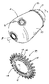
Referring now to FIGURES 12-14, drive ring 39 (e.g. sprocket, spider, daisy,
etc.) includes a hub 108 and extensions 110. Hub 108 (e.g., mount, coupling,
etc.) is a generally cylindrical member that is designed to couple to mixing
drum drivetrain 1 8 . Hub 108 includes an inner side 1 12 (i.e., the side of
hub
108 that faces drum 16) and an outer side 1 14 (i.e., the side of hub 108 that
faces away from drum 16). A circular recess 116, which helps to facilitate the
secure coupling of drivetrain 18 to hub 108, is provided in outer side 114.
The
diameter of recess 1 1 6 is such that the circumference of recess 1 16 lies
approximately half way between an inner diameter 1 18 and an outer diameter
120 of hub 108. Apertures 121, which allow hub 108 to be bolted or
otherwise coupled to mixing drum drivetrain 18, are spaced circumferentially
around a base 123 of recess 116. A flange 122, which also facilitates the
coupling of hub 108 to mixing drum drivetrain 18, extends radially outwardly
from outer diameter 120 proximate outer side 114 of hub 108. An inner side
124 of flange 122 is tapered and gradually extends from the circumference of
flange 122 toward outer diameter 120 of hub 108 as flange 122 extends
toward drum 16. According to various alternative embodiments, the hub may
be configured to be coupled to any one of a variety of different mixing drum
drivetrains. Accordingly, the hub may take any one of a variety of different
shapes and include any one or more of a variety of different features or
elements that allow the hub to be coupled to a particular drive drivetrain.
-24-
CA 02535772 2006-02-14
WO 2005/018895 PCT/US2003/025438
A plurality of extensions 110 (e.g., fingers, projections, spikes, tangs,
etc.) are
spaced apart along the circumference of hub 108 and generally extend from
hub 108 proximate inner side 112. According to an exemplary embodiment,
each extension is a generally rectangular or triangular member that extends
both radially outwardly from hub 108 and away from inner side 1 12 of hub
108. According to another exemplary embodiment, each extension is a
generally triangular member. Each extension 1 10 includes an aperture or
opening 126 that extends through the center of each extension 1 10 and that
has the same general shape as the outline or periphery of extension 110.
FIGURE 15 illustrates another exemplary embodiment of a drive ring. Drive
ring 250 (e.g. sprocket, spider, daisy, etc.) includes a hub 252 and
extensions
254. Hub 252 (e.g., mount, coupling, etc.) is a generally cylindrical member
that is designed to couple to mixing drum drivetrain 18. Hub 252 is
substantially similar to hub 108 described above in relation to drive ring 39,
except extra material between the holes is removed to reduce the weight of
drive ring 250. According to various alternative embodiments, the hub may be
configured to be coupled to any one of a variety of different mixing drum
drivetrains. Accordingly, the hub may take any one of a variety of different
shapes and include any one or more of a variety of different features or
elements that allow the hub to be coupled to a particular drive drivetrain.
A plurality of extensions 254 (e.g., fingers, projections, spikes, tangs,
etc.) are
spaced apart along the circumference of hub 252 and generally extend from
hub 252. According to an exemplary embodiment, each extension is a
generally rectangular member that extends both radially outwardly from hub
252 and away from hub 252. Each extension 254 includes an aperture or
opening 256 that extends through the center of each extension 254 and that
has the same general shape as the outline or periphery of extension 254.
According to various exemplary and alternative embodiments, the drive ring
may include no extensions or it may include up to or over 20 extensions.
According to one exemplary embodiment, the drive ring includes 12
-25-
CA 02535772 2006-02-14
WO 2005/018895 PCT/US2003/025438
extensions. Generally, the smaller the extensions, the more extensions may be
provided around the hub. According to other exemplary embodiments, the
space S between the extensions ranges from 0 to 6 inches. According to
other exemplary embodiments the aperture provided in the extensions is of size
that is sufficient to allow resin used in the construction of outer drum layer
36
to infiltrate or enter the aperture. According still other alternative or
exemplary
embodiments, the apertures may be larger or smaller, which as the effect of
reducing or increasing the weight of the drive ring. According to still other
exemplary embodiments, the extensions angle away from the side of the hub
that is closest to the barrel by approximately 15 degrees. According to one
exemplary embodiment, the extensions angle such that the contour with the
shape of the drum.
According to an exemplary embodiment, the drive rings are cast from an off-
tempered ductile iron, preferably an 805506 ductile iron. According to various
alternative embodiments, the drive ring may be made from one or more of a
variety of different materials using one or more of a variety of different
methods. For example, the hub could be made separately from the extensions,
and then the two could be welded, bolted, or otherwise coupled together to
form the drive ring. According to other alternative embodiments, dimensions
(such as the thicknesses, widths, heights, etc.) of the hub and extensions may
be varied depending on the specific application in which the drive ring will
be
used.
The drive rings are preferably coupled or attached to larger end 30 of drum 16
while the outer drum layer 36 is being applied over inner drum layer 34. This
allows the fibers that are wrapped around inner drum layer 34 to be wrapped
or woven between and/or around each of the extensions, or even through the
apertures. This also allows the resin used to make outer drum layer 36 to
enter and fill the spaces between the extensions as well as the spaces
provided by the apertures in the extensions. The infiltration of the resin and
the weaving of the fibers around and through the extensions helps to
-26-
CA 02535772 2006-02-14
WO 2005/018895 PCT/US2003/025438
strengthen the connection of the drive ring to drum 16 and helps to distribute
the loads that are transferred between drum 16 and the drive ring. Because
the extensions are incorporated into drum 16, the extensions extend from the
drive ring at an angle that allows the extensions to fit within the contour of
drum 16.
According to various alternative embodiments, the apertures and/or the
extensions may be any one of a variety of different shapes, such as
rectangular, trapezoidal, oval, circular, etc. Moreover, any one or more of
the
apertures and/or the extensions may be shaped differently than one or more of
the other apertures and/or extensions. According to other alternative
embodiments, the extensions may be solid and not include apertures.
According to still other alternative embodiments, the angle or orientation of
the
extensions with respect to the drive ring may be varied to accommodate
different drum shapes and configurations.
Referring back to FIGURES 1-3, drum 16 also includes roller ring 35. Roller
ring 35 is a circular member that fits around the outside of drum 16 at a
location approximately one-third of the way from the smaller end of drum 16
toward larger end 30. A surface 128 provided on the outer diameter of roller
ring 35 is configured to serve as the surface against which rollers 130
(illustrated in FIGURE 1) (which support a portion of the weight of drum 16
along with drivetrain 18 and drive ring 39) ride as drum 16 rotates. According
to an exemplary embodiment, roller ring 35 is made from a polymer material.
According to various alternative embodiments, the roller ring is made from one
or more of a variety of different materials, including but not limited to
metals,
plastics, elastomers, ceramics, composites, etc.
Referring now to FIGURES 2 and 3, mixing drum 16 is coupled to, and
supported by, chassis 12 of truck 10 and is configured to be at least
partially
filled with concrete such that when concrete is desired in a particular
location,
the concrete is loaded within drum 16 and transported to the desired location
by truck 10. The spiral configuration of each projection 32 provides a screw-
-27-
CA 02535772 2006-02-14
WO 2005/018895 PCT/US2003/025438
or auger-like action when drum 16 is rotated. Depending on the direction of
rotation of drum 16, projections 32 will either force the concrete within drum
16 out of opening 28, or projections 32 will force the concrete toward larger
end 30, which tends to mix the concrete. Accordingly, while the concrete is
being transported within drum 16, mixing drum drivetrain 18 applies a torque
to drum 16 that causes drum 16 to rotate about its longitudinal axis 31 in a
first direction that results in the mixing of the concrete. Once truck 10
reaches
the destination where the concrete is desired, mixing drum drivetrain 18
applies a torque to drum 16 that causes drum 16 to rotate about its
longitudinal axis in a direction opposite the first direction, which
discharges the
concrete out of opening 28. As drum 16 rotates and the concrete within drum
16 contacts and applies a force to projections 32, tapered base portion 42 and
support member 48 help to prevent projection 32 from failing or bending over
under the load of the concrete. Moreover, as the concrete is moved within
drum 16, it will travel over the seams between sections 41 and 43 of inner
drum wall 34. Ramps 40 help to reduce the wear in the areas around the
seams by directing the concrete away from the seam. Hatch cover assemblies
37 and 200 cover opening 67 provided within barrel 33 and help to seal the
opening and prevent the concrete from escaping through opening 67. Hatch
cover assemblies 37 and 200 also couple to barrel 33 in such a way that does
not significantly weaken barrel 33 in the areas around opening 67. The design
of drive rings 18 and 250 allows either one of them to be coupled to barrel 33
and withstand the various forces applied to drive rings 18 and 250 and barrel
33. The apertures in drive rings 18 and 250 also help to reduce weight.
The composite and plastic construction of the drum helps effective mixing
allow the inner surfaces of the drum, and helps to minimize any heat that may
be retained within drum. The materials and processes used to construct the
drum also allow the drum to be manufactured with minimal labor, to maintain a
relatively light weight, to withstand the normal loads, and to be more
resistant
to wear than conventional metal mixing drums. Moreover, the drive rings and
hatch cover assemblies effectively perform the functions of similar devices
-28-
CA 02535772 2006-02-14
WO 2005/018895 PCT/US2003/025438
used in metal mixing drums and at the same time are compatible with a
composite or plastic drum. The drive rings and hatch cover assemblies may
also be produced cheaper and lighter than the metal mixing drum counterparts.
Although the present inventions are been described in relation to a single
drum,
it should be understood that the different exemplary and alternative
embodiments may be used together, or they may be used separately, in one or
more different mixing drums.
Although the present inventions have been described with reference to
exemplary embodiments, workers skilled in the art will recognize that changes
may be made in form and detail without departing from the spirit and scope of
the invention. For example, although different exemplary embodiments may
have been described as including one or more features providing one or more
benefits, it is contemplated that the described features may be interchanged
with one another or alternatively be combined with one another in the
described exemplary embodiments or in other alternative embodiments.
Because the technology of the present invention is relatively complex, not all
changes in the technology are foreseeable. The present invention described
with reference to the exemplary embodiments and set forth in the following
claims is manifestly intended to be as broad as possible. For example, unless
specifically otherwise noted, the claims reciting a single particular element
also
encompass a plurality of such particular elements.
-29-