Note: Descriptions are shown in the official language in which they were submitted.
CA 02536034 2007-12-17
TITLE OF THE INVENTION:
METHOD AND APPARATUS FOR DISPENSING COMPRESSED GAS
BACKGROUND OF THE INVENTION
[0002] The present invention relates to a method and apparatus for dispensing
compressed gas. More particularly, the present invention is directed to a
method and
apparatus useful for transferring a compressed gas from a refueling station
into one or
more storage tanks.
[0003] Because of the interrelationship between the temperature, pressure, and
density of gases, the amount of hydrogen, H2, (or compressed natural gas
(CNG)) that
can safely be introduced into a storage tank, such as a vehicle storage tank,
during
refueling necessarily depends upon factors such as the volume, design
pressure, and
temperature of the tahk, and the temperature and pressure of the compressed
gas inside
the tank. Industry convention sets the pressure rating for H2 fuel tanks at
the standard
temperature of 15 degrees Celsius, so nominal pressure ratings such as 250 bar
(25
MPa), 350 bar (35 MPa), 500 bar (50 MPa) and 700 bar (70 MPa), correspond to
an
internal gas temperature of 15 degrees Celsius. During rapid refueling of
hydrogen, the
internal tank temperature will typically rise about 50 degrees Celsius due to
adiabatic
compression of the gas and the reverse Joule-Thompson effect. After the tank
is filled,
the temperature and pressure inside the tank will decrease as the gas cools.
Wide
variations in ambient temperature above or below the standard condition of 15
degrees
Celsius can also have a significant effect on the indicated pressure inside
the tank during
and after refueling.
[0004] As referred to herein, a compressed gas includes pressurized gas and
supercritical fluids. A pressurized gas is a fluid below its critical pressure
and below its
-1-
CA 02536034 2006-02-10
critical temperature. A supercritical fluid is a fluid above either its
critical pressure or its
critical temperature.
[0005] It is desirable to have a method for dispensing compressed gas to a
receiving
vessel without the problem or risk of overfilling, so that an no time would
the rated
pressure in the tank be exceeded.
BRIEF SUMMARY OF THE INVENTION
[0006] The present invention relates to a method for dispensing a compressed
gas
from a compressed gas source to a receiving tank comprising connecting a
dispensing
connector to the receiving tank, determining an initial equivalent density of
the
compressed gas in the receiving tank, selecting a target equivalent density
for the
receiving tank, calculating a predetermined quantity of compressed gas to be
added to
the receiving tank as a function of at least the target equivalent density and
the initial
equivalent density, transferring the compressed gas from the compressed gas
source to
the receiving tank while measuring an accumulated quantity of compressed gas
transferred, and controlling the flow of the compressed gas as a function of
the
accumulated quantity and the predetermined quantity.
[0007] The step of controlling the flow may include stopping the flow of the
compressed
gas when the accumulated quantity reaches the predetermined quantity or is
within a
range of the predetermined quantity.
[0008] The method of the present invention may further comprise the step of
measuring a final equivalent density of the compressed gas in the receiving
tank.
[0009] The present invention also relates to a method for dispensing a
compressed
gas from a compressed gas source to a receiving tank comprising connecting a
dispensing connector to the receiving tank, determining an initial equivalent
density of
the compressed gas in the receiving tank by a direct density sensor selected
from the
group consisting of a capacitive sensor, a vibrating element sensor, and a
nucleonic
sensor, selecting a target equivalent density for the receiving tank,
calculating a
predetermined quantity of compressed gas to be added to the receiving tank as
a
function of at least the target equivalent density and the initial equivalent
density,
transferring the compressed gas from the compressed gas source to the
receiving tank
-2-
CA 02536034 2006-02-10
while measuring an accumulated quantity of compressed gas transferred, and
controlling
the flow of the compressed gas as a function of the accumulated quantity and
the
predetermined quantity.
[0010] The present invention also relates to an apparatus for dispensing a
compressed
gas to a receiving tank comprising a compressed gas source, a valve in fluid
communication with the compressed gas source where the valve is operable by a
valve
signal, a fluid tight conduit having a first end and a second end wherein the
first end is in
fluid communication with the valve and wherein the second end is in fluid
communication
with a dispensing connector for connecting to the receiving tank, a means for
determining the equivalent density of the compressed gas in the receiving
tank, a means
for calculating a predetermined quantity of compressed gas to be added to the
receiving
tank as a function of at least a target equivalent density and an initial
equivalent density
where the means for calculating is in communication with the means for
determining an
initial equivalent density, a means for measuring an accumulated quantity of
compressed
gas dispensed, a means for comparing the accumulated quantity of compressed
gas
dispensed with the predetermined quantity of compressed gas to be added to the
receiving tank, and a means for generating the valve signal in communication
with the
means for comparing the accumulated quantity of compressed gas dispensed with
the
predetermined quantity of compressed gas to be added to the receiving tank.
[0011] An electronic controller may be the means for generating the valve
signal and
the means for comparing the accumulated quantity of compressed gas dispensed
with
the predetermined quantity of compressed gas to be added to the receiving tank
.
[0012] An electronic controller may be the means for generating the valve
signal, the
means for comparing the accumulated quantity of compressed gas dispensed with
the
predetermined quantity of compressed gas to be added to the receiving tank,
and the
means for calculating .
[0013] The means for determining the equivalent density in the receiving tank
may be a
sensor selected from the group consisting of a capacitive sensor, a vibrating
element
sensor, and a nucleonic sensor.
[0014] The means for determining the equivalent density in the receiving tank
may be
integrated with the dispensing connector and/or integrated with the receiving
tank.
-3-
CA 02536034 2006-02-10
[0015] The means for measuring an accumulated quantity of compressed gas
dispensed may comprise a mass flow meter.
BRIEF DESCRIPTION OF SEVERAL VIEWS OF THE DRAWINGS
[0016] FIG. 1 is a schematic view of an embodiment of the present invention
for
dispensing compressed gas.
[0017] FIG. 2 is a schematic view of another embodiment of the present
invention for
dispensing compressed gas.
DETAILED DESCRIPTION OF THE INVENTION
[0018] One embodiment of the current invention relates to a method for
dispensing a
compressed gas from a compressed gas source to a receiving tank including the
steps
of connecting a dispensing connector to the receiving tank, determining an
initial
equivalent density of the compressed gas in the receiving tank, selecting a
target
equivalent density for the receiving tank, calculating a predetermined
quantity of
compressed gas to be added to the receiving tank as a function of the target
equivalent
density and the initial equivalent density, transferring the compressed gas
from the
compressed gas source to the receiving tank while measuring an accumulated
quantity
of compressed gas transferred, and controlling the flow of the compressed gas
as a
function of the accumulated quantity and the predetermined quantity. The
method may
optionally include a step for measuring the final equivalent density in the
receiving tank.
[0019] The compressed gas may be hydrogen gas and it may be compressed natural
gas.
[0020] The equivalent density may be the mass density (mass per volume), molar
density (moles per volume), or a functional equivalent, for example, any
density directly
related to these quantities. In case of a constant volume receiving tank, the
equivalent
density may also be mass, moles, or functional equivalent.
[0021] The initial equivalent density is the equivalent density of the
compressed gas in
the receiving tank prior to dispensing. The initial equivalent density may be
determined
30. directly using a density sensor, for example a capacitive sensor,
vibrating element
-4-
CA 02536034 2006-02-10
sensor, or nucleonic sensor. The initial equivalent density may also be
determined by
measuring the temperature and pressure in the receiving tank and calculating
the density
based on an equation of state.
[0022] The target equivalent density is the equivalent density of the
compressed gas
that is sought at the end of dispensing. The target equivalent density may be
input as
some percent of maximum allowed equivalent density for the receiving tank. The
maximum allowed equivalent density or tank rated density, may be calculated
based on
the receiving tank specifications, for example, a manufacturer's
specification, for a full
tank. Tank rated pressure and temperature may be converted to a tank rated
density.
Therefore, the tank may be filled such that at no time during the dispensing
cycle or
afterward does the actual pressure inside the receiving tank exceed the
manufacturer's
maximum allowable pressure for that tank. The target equivalent density may be
selected based on the receiving tank specifications, for example pressure
rating, and the
anticipated temperature range of the compressed gas inside the receiving tank.
The
target equivalent density may be determined from a signal or data from the
receiving
tank. The target equivalent density may also be selected based on any desired
safety
margin.
[0023] The predetermined quantity of compressed gas to be added to the
receiving
tank can be calculated depending on the initial density in the receiving tank,
the target
density, and the volume of the tank. The calculation may be done manually or
by
electronic means, for example a controller or computer.
[0024] The flow of compressed gas is initiated and during the transferring
step, the flow
of compressed gas is measured so that the accumulated quantity, or totalized
flow, is
obtained. The measurement of the accumulated quantity transferred may be done
by
any means known in the art, such as a conventional mass flow meter. This
accumulated
quantity dispensed may be used for billing purposes.
[0025] The flow of the compressed gas is controlled, for example by an
electronic
controller and a valve. The flow is controlled by the opening and closing of
the valve as a
function of at least the accumulated quantity and the predetermined quantity.
The flow
may be continued until the accumulated quantity reaches the predetermined
quantity or
is within some select range of the predetermined quantity.
[0026] Optionally, the equivalent density in the receiving tank may be
measured after
the flow of compressed gas is stopped. The final equivalent density may be
determined
-5-
CA 02536034 2006-02-10
by measuring the temperature and pressure in the receiving tank and
calculating the
density based on an equation of state. Alternatively, the final equivalent
density may be
determined directly using a density sensor, for example a capacitive sensor,
vibrating
element sensor, or nucleonic sensor.
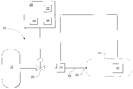
[0027] Referring to the drawings, wherein like reference numbers refer to like
elements
throughout the views, there is shown in FIG. 1, an apparatus 10 of the current
invention
suitable for performing the inventive method for dispensing compressed gas to
a
receiving tank 14 in accordance with an embodiment of the present invention.
The
apparatus 10 for dispensing compressed gas comprises a compressed gas source
12, a
valve 20, a means for measuring an accumulated quantity of compressed gas
dispensed
16, a conduit 18 in fluid communication with a dispensing connector 30, a
means for
determining the equivalent density 40, a means for calculating a predetermined
quantity
of compressed gas to be added to the receiving tank 32, a means for comparing
the
accumulated quantity of compressed gas dispensed with the predetermined
quantity of
compressed gas to be added 34, and a means for generating a valve signal 36.
As
shown in this figure, the means for calculating a predetermined quantity of
compressed
gas to be added to the receiving tank 32, the means for comparing the
accumulated
quantity of compressed gas dispensed with the predetermined quantity of
compressed
gas to be added 34, and the means for generating a valve signal 36 may be
accomplished by a single device, for example, an electronic controller or
computer 28. It
is understood that these functions may be accomplished by a single device or
multiple
devices. When reference is made to electronic controller 28, the equivalency
to the
appropriate means 32, 34 and 36 is understood.
[0028] The compressed gas source 12 may be a large volume storage tank, hydril
tubes, a compressed gas supply line, a compressor discharge line, or any
combination of
these elements suitable for use in supplying gas to the receiving tank in an
amount and
at a pressure great enough to achieve a desired fill rate, density, and
pressure in the
receiving tank. The compressed gas source may also originate from a liquid
source that
has been pressurized and heated in a heat exchanger. In the case of hydrogen,
the
compressed gas source may also originate from metal hydrides or chemical
hydrides.
[0029] The valve 20 is in fluid communication with the compressed gas source
12 and
regulates the flow from the compressed gas source 12 to the receiving tank 14.
The
valve is operable, i.e. opened and closed, via a valve signal. The valve 20
may be
-6-
CA 02536034 2006-02-10
pneumatically actuated or electrically actuated. Such valves are conventional
in the art.
Valve 20 may be constructed of any material known in the art compatible with
the
compressed gas. In case of a pneumatically operated valve, an electric signal
must be
converted to a pneumatic signal.
[0030] The means for measuring an accumulated quantity of compressed gas
dispensed 16, for example a mass flow meter or functionally equivalent device,
is in fluid
communication with the valve 20. The means for measuring an accumulated
quantity of
compressed gas dispensed 16 may be used to measure the accumulated quantity of
compressed gas transferred and communicate the accumulated quantity to the
electronic
controller 28. The means for measuring an accumulated quantity of compressed
gas
dispensed 16 may be between the valve 20 and the receiving tank 14 as shown in
FIG. 1
or between the compressed gas source 12 and the valve 20. Mass flow meters are
conventional and well known in the art. The total mass flow may be determined
by
integrating the product of density and the volume flow rate. The volume flow
rate may be
determined by a conventional means, for example a turbine meter. The density
may be
determined by a density sensor, for example a capacitive sensor, vibrating
element
sensor, or nucleonic sensor. U.S. Pat. Nos. 3,715,912, 4,312,235, and
5,687,100
illustrate examples of mass flow meters comprising a vibrating element sensor.
U.S. Pat.
No. 4,881,412 illustrates an example of a mass flow meter comprising a
nucleonic
sensor.
[0031] The conduit 18 links the means for measuring an accumulated quantity of
compressed gas dispensed 16 to a dispensing connector 30. The conduit 18 may
be
constructed of any material known in the art compatible with the compressed
gas. The
conduit 18 may be rigid or flexible.
[0032] The dispensing connector 30 may be any suitable connector for mating to
the
receiving tank 14. Dispensing connectors are conventional in the art.
Dispensing
connector 30 may be constructed of any material in the art compatible with the
compressed gas.
[0033] The means for determining the equivalent density 40 may be a density
sensor.
The density sensor may be disposed inside the receiving tank 14 to measure the
density
of the fluid inside the receiving tank 14. The density sensor may include a
temperature
sensor (not shown) to improve the accuracy of the density measurement. The
density
sensor may be incorporated or integrated in the receiving tank 14,
incorporated or
-7-
CA 02536034 2006-02-10
integrated with the dispensing connector 30, or it may be a separate device
that is
connected to the receiving tank 14 at the dispensing location. More than one
density
sensor may be used as the means for determining the equivalent density 40. The
means
for determining the equivalent density 40 may be a capacitive sensor,
vibrating element
sensor, or nucleonic sensor. The means for determining the equivalent density
40 may
include a signal generator for generating a sensor signal corresponding to the
density of
the fluid inside the receiving tank 14. The signal generator is in
communication with the
electronic controller 28. The communication between the signal generator of
the density
sensor and the electronic controller 28 may be hardwired or wireless. The
signal may be
relayed to the electronic controller 28 by, for example, any conventional,
commercially
available devices or systems as desired.
[0034] A capacitive sensor is defined as any sensor that senses a fluid's
dielectric
properties. Examples of capacitive sensors are illustrated in US Pat. Nos.
3,421,077,
3,903,478, 4,835,456, and 5,027,076.
[0035] A vibrating element sensor is defined as any sensor that has a
vibrating
structure. It is known that, in a vibration densitometer, if a structure is
vibrated at its
resonant frequency while being immersed in a fluid, the density of the said
fluid can be
determined by measuring the resonant frequency. The vibrating element may be a
vane
as described in U.S. Pat. No. 3,677,067, a tuning fork as described in U.S.
Pat No.
4,526,480, a cylinder as described in U.S. Pat. No. 6,029,501, a double-bar
double-
ended resonator or double-bar single-ended as described in U.S. Pat. No.
4,535,638, or
any other vibrating element known in the art. The vibrating element, for
example a tuning
fork and vane, may be surrounded by the fluid to be measured or the fluid may
flow
inside of the vibrating element, for example a tube. Examples of vibrating
element
sensors are also illustrated in U.S. Pat. Nos. 3,426,593, 3,715,912,
4,574,639,
4,644,796, 4,644,803,
[0036] A nucleonic sensor is defined as any sensor that uses a radiation
source and
detector. The radiation may be x-ray as in U.S. Pat. No. 4,277,681, gamma-ray
(y-ray)
as in U.S. Pat. Nos. 5,166,964 and 2,898,466, neutrons as in U.S. Pat. No.
4,582,991,
beta-ray as in U.S. Pat. No. 2,757,290 or other radiation source known in the
art.
Nucleonic, aiso called radiation type, sensors are also discussed in U.S. Pat.
Nos.
2,763,790, 2,968,729, 2,922,888, 3,196,271, and 6,548,814.
-8-
CA 02536034 2006-02-10
[0037] The electronic controller 28 may provide several functions. The target
equivalent density for the receiving tank may be selected by the user as a
percentage of
the maximum allowed equivalent density and input to the electronic controller
28. The
maximum allowed equivalent density may be communicated automatically from the
receiving tank 14 to the electronic controller 28.
[0038] The electronic controller 28 may be hardwired or wireless communication
with
the sensors and valve 20.
[0039] As discussed above, the electronic controller 28 may be the means for
calculating a predetermined quantity of compressed gas to be added to the
receiving
tank. From the target equivalent density and the initial equivalent density,
the electronic
controller 28 may calculate a predetermined quantity of compressed gas to be
added to
the receiving tank 14. For the sake of simplicity, an ideal gas equation of
state will be
used to illustrate the point. A 1 cubic meter receiving tank with an initial
pressure of 10
MPa and a temperature_ of 15 degrees Celsius has a molar density of about 4176
moles/m3. If the target density is 20882 moles/m3 then the amount that can be
added is
16706 moles. This would correspond to a final pressure of 50 MPa at 15 degrees
Celsius.
[0040] When the valve 20 is open, compressed gas is transferred from the
compressed
gas source 12 to the receiving tank 14. As the compressed gas is transferred
from the
compressed gas source 12 to the receiving tank 14, the means for measuring an
accumulated quantity of compressed gas dispensed 16 measures the mass flow
rate
and communicates the result to the electronic controller 28, which calculates
the
accumulated quantity of compressed gas transferred. The electronic controller
28
compares the accumulated quantity to the predetermined quantity and provides a
signal
to the valve 20 thereby controlling the flow of the compressed gas. When the
accumulated quantity is within some selected range of the predetermined
quantity, the
electronic controller 28 may communicate with the valve 20 to stop the flow of
compressed gas.
[0041] Optionally, the density sensor used to measure the initial equivalent
density
may measure the density of the compressed gas in the receiving tank 14 after
the valve
20 is closed to obtain a final equivalent density of the compressed gas in the
receiving
tank 14.
-9-
CA 02536034 2006-02-10
[0042] An apparatus 10 suitable for performing the inventive method for
dispensing
compressed gas to a receiving tank 14 in accordance with another embodiment of
the
present invention is iilustrated in FIG. 2. The apparatus 10 for dispensing
compressed
gas comprises a compressed gas source 12, a valve 20, a means for measuring an
accumulated quantity of compressed gas dispensed 16, a conduit 18 in fluid
communication with a dispensing connector 30, a pressure sensor 22, a
temperature
sensor 24, and an electronic controller 28. In this alternative embodiment,
the means for
determining an initial equivalent density may be a pressure sensor 22 and a
temperature
sensor 24. Using an appropriate equation of state for the compressed gas the
initial
equivalent density may be calculated by, for example, the electronic
controller 28, from
the pressure and temperature measurements.
[0043] Other than the density measurements, all other features and steps of
the
invention may be achieved as described above for FIG 1.
[0044] To use the apparatus of the invention, the dispensing connector 30 is
connected
to the receiving tank 14. As applicable, the electronic controller 28 may be
put in
hardwired or wireless communication with the means for determining the
equivalent
density 40, which may include the temperature sensor 24 and pressure sensors
22
embodiment. The electronic controller 28 may collect user information. The
electronic
controller 28 may authorize the use of the station for an authorized user by
any number
of commonly used methods such as a credit card, debit card, or other magnetic
or
electronically encoded card, with our without an identifying Personal
Identification
Number or "PIN." The electronic controller 28 and the means for determining
the
equivalent density 40 communicate, and an initial equivalent density in the
receiving tank
is stored in the electronic controller 28. The electronic controller 28 may
read a tank
rated density for the receiving tank 14 or the user may input the tank rated
density. The
user may input the target equivalent density for the receiving tank as a
percentage of the
maximum allowed equivalent density to the electronic controller 28
corresponding to the
desired fill amount. The electronic controller calculates a predetermined
quantity of
compressed gas to be added as a function of the target equivalent density and
the initial
equivalent density. The electronic controller instructs the valve 20 to open
and
compressed gas is transferred to the receiving tank 14. The means for
measuring an
accumulated quantity of compressed gas dispensed 16 communicates the mass flow
to
the electronic controller 28 and the electronic controller calculates the
accumulated
quantity and compares to the predetermined quantity. When the accumulated
quantity
-10-
CA 02536034 2006-02-10
comes within a selected range of the predetermined quantity, the electronic
controller 28
instructs the valve 20 to close.
[0045] After filling is complete the dispensing connector 30 is detached from
the
receiving tank 14 and communication between the means for determining the
equivalent
density 40 and electronic controller 28 may be stopped. The electronic
controller 28 may
communicate with another computer for billing the user for the accumulated
quantity of
compressed gas transferred.
[0046] Although illustrated and described herein with reference to specific
embodiments, the present invention nevertheless is not intended to be limited
to the
details shown. Rather, various modifications may be made in the details within
the scope
and range of equivalents of the claims without departing from the spirit of
the invention.
-11-