Note: Descriptions are shown in the official language in which they were submitted.
CA 02536304 2006-02-20
WO 2005/033433 PCT/CA2003/001469
TENSION ANCHORAGE SYSTEM
The present invention relates to an anchorage system for fibre reinforced
polymer components.
BACKGROUND OF THE INVENTION
A pre-stressed, pre-tensioned, or post-tensioned, concrete structure has
significantly
greater load bearing properties compared to an un-reinforced concrete
structure. Steel
rods or tendons are used almost universally as the pre-stressing or post-
tensioning
members. The steel rods and associated anchoring components may become exposed
to many corrosive elements, such as de-icing chemicals, salt or brackish
water. If this
occurs, the rods may corrode, thereby causing the surrounding concrete
structure to
fracture.
Fibre-reinforced polymer (FRP) rods have been used in place of conventional
reinforcing rods. The advantages of using a FRP rod include its light weight
relative to
steel, resistance to corrosion and its high tensile strength, which in some
cases may
exceed that of steel. Fibre reinforced polymer rods, however, do not have
correspondingly high transverse compressive strength. As a result, traditional
clamping
or anchor mechanisms used for steel rods crush the rod at its load bearing
area, which
may lead to premature failure of the FRP tendon at the anchorage point.
Many solutions to this problem have been proposed, but none have resolved this
problem satisfactorily. For example, Shrive et al (US 6,082,063) proposes a
wedge
anchor in which the taper of the wedge is greater than the taper of its
receiving bore.
This differential tapering results in a higher clamping force being applied
away from
the rod's loaded area. However, Shrive et al requires very,precise pre-seating
of the
wedge. Thus, its effectiveness is largely dependant on the precision of the
pre-seating.
Further, the Shrive et al design is not a robust design and-it is not tolerant
of machinng
inaccuracies.
-1-
CA 02536304 2006-02-20
WO 2005/033433 PCT/CA2003/001469
There remains a need for a robust and easy to use anchorage system that is
able to
exploit the high tensile strength and non-corroding properties of carbon fibre
reinforced
polymer rods.
SUMMARY OF THE INVENTION
According to the present invention there is provided a wedge anchor comprising
a
barrel having a wedge receiving face opposite a rod receiving face, a passage
extending
therethrough between the wedge receiving face and the rod receiving face, the
pass~.ge
narrowing toward the rod receiving face and having an axial cross-sectional
profile
defining a convex arc; and, a plurality of wedges insertable into the passage,
each of the
wedges having a respective inner wedge face for defining a rod receiving
passage for
receiving a rod and an outer wedge face, opposite the inner wedge face, in
axial cross-
section having a profile complementary to the inner barrel face.
The convex arc may define a radius of curvature.
The wedge anchor may further comprise a sleeve, which is insertable into the
rod
receiving passage for receiving an end portion of the rod, that may be
comprised of a
malleable metal, such as copper, aluminium and alloys thereof.
The present invention also provides for a method of testing the tensile
strength of a
carbon reinforced polymer rod comprising the steps of securing a wedge anchor
according to an embodiment of the present invention to a rod end portion;
applying a
tensile force to the wedge anchor sufficient to break the rod; and, measuring
the applied
force.
BRIEF DESCRIPTION OF THE DRAWINGS
These and other features of the preferred embodiments of the invention will
become
more apparent in the following detailed description in which reference is made
to the
appended drawings wherein:
Figure 1 is a schematic cross-sectional view of a wedge anchor according to an
embodiment of the present invention;
_2_
CA 02536304 2006-02-20
WO 2005/033433 PCT/CA2003/001469
Figure 2 is a schematic cross-sectional view of a wedge anchor according to an
alternative embodiment of the present invention;
Figure 3 is a schematic cross-sectional view of a wedge anchor according to a
further
alternative embodiment of the present invention;
Figure 4(a) is a plan view of a wedge of a wedge anchor according to an
embodiment
of the present invention;
Figure 4(b) is a cross sectional view of a wedge of a wedge anchor according
to an
embodiment of the present invention;
Figure 5 is a cross-sectional view of a wedge and barrel portion of a wedge
anchor
according to an embodiment of the present invention illustrating the relative
contact
force exerted along the length of the wedge;
Figure 6(a) is a schematic cross-sectional view of the rod-sleeve-wedge
interface of a
pre-seated wedge anchor according to an embodiment of the present invention;
Figure 6(b) is a schematic cross-section view of the rod-sleeve-wedge
interface of a
secured wedge anchor according to an embodiment of the present invention;
Figure 7(a) is a schematic cross-sectional view of the rod-layer-wedge
interface of a
pre-seated wedge anchor according to an embodiment of the present invention;
Figure 7(b) is a schematic cross-section view of the rod-layer-wedge interface
of a
secured wedge anchor according to an embodiment of the present invention;
Figure 8(a) is a cross-sectional view of a cast concrete structural member;
Figure 8(b) is a cross-sectional view of the cast concrete structural member
of Figure
8(a) illustrating a wedge anchor according an embodiment of the present
invention
secured to a fibre reinforced polymer rod;
Figure 8(c) is a cross-sectional view of the cast concrete structural member
of Figure
8(b) illustrating wedge anchors secured to both ends of the fibre reinforced
.polymer
rod; and,
-3-
CA 02536304 2006-02-20
WO 2005/033433 PCT/CA2003/001469
Figure 9 is a schematic representation of a system for testing the tensile
strength of a
fibre reinforced polymer rod employing a wedge anchor according to an
embodiment of
the present invention.
DESCRIPTION OF THE PREFERRED EMBODIMENTS
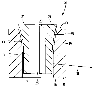
Referring to Figures 1 to 4(a) and (b), a wedge anchor 10 according to an
embodiment
of the present invention is illustrated. The wedge anchor 10 is comprised of a
barrel 11
that has a wedge receiving face 13, which is opposite a rod receiving face 15.
A
passage 17 extends through the barrel 11 between the wedge receiving face 13
and the
rod receiving face 1 S and narrows toward the rod receiving face 15. In an
axial cross-
sectional profile, the passage 17 defines a convex arc 19. In a preferred
embodiment of
the present invention, the axial cross-sectional profile of the convex arc is
defined by a
radius of curvature 31 described as subtended angle less than 0.5 pi radians.
The
wedge anchor 10 also includes a plurality of wedges 21, which are insertable
into the
passage 17. Each of the wedges 21 has a respective inner wedge face 23 for
defining a
rod receiving passage 25 for receiving a rod 27 and an outer wedge face 29,
which is
opposite the inner wedge face 23. The outer wedge face 29, in axial cross-
section, has
a profile complementary to the convex arc 19.
The wedge anchor 10 may include as few as two wedges 21, but generally will
employ
between 4 and 6 wedges 21. In a preferred embodiment, the wedge anchor 10 is
comprised of 4 wedges 21 of equal size.
The wedges 21 have a length 39 selected to ensure that they do not extend
beyond the
rod receiving face 15 of the barrel 11 when the wedge anchor 10 is in its
assembled and
secured configuration. In a preferred embodiment, the respective outer wedge
faces 29
of wedges 21 have a length 39 less than O.5 pi radians. In an alternate
embodiment, the
length of the wedges 21 may extend beyond the rod receiving face of the
barrel,
provided a cast concrete structural member having a rod receiving entrance is
configured to accommodate the extending wedges 21 without hindering the
performance of the wedge anchor 10.
- 4-
CA 02536304 2006-02-20
WO 2005/033433 PCT/CA2003/001469
The barrel 11. and wedges 21 may be comprised of a hard material, such as a
hard
metal. In a preferred embodiment, the hard metal is stainless steel. However,
any hard
material known to those skilled in the art may be employed, such as titanium,
copper
alloys or ceramic materials. In an alternate embodiment, the barrel 11 and
wedges 21
S may be comprised of a hard plastic as is known to those skilled in the art.
Referring to Figure 5, a cross-sectional view of a portion of the wedge anchor
10 in its
assembled configuration and an accompanying force curve are illustrated. An
inward
radial or compressive contact force (F) is exerted along the length 39 of the
wedge 21
when the wedges 21 are secured in the passage 17. The force curve illustrates
the
relative inward radial or compressive contact force (F) that is exerted along
the length
of the wedge 21. Line F illustrates that the compressive force F varies non-
linearly
over the length of the wedge anchor 10 as a function of the tangent along a
surface
point of the convex arc 19 and approaches a maximum toward the wedge receiving
face
of the barrel and a minimum toward the rod receiving face 13 of the barrel 11.
15 Referring to Figure 2, a preferred embodiment of the wedge anchor 10 is
illustrated,
which further includes a sleeve 33, which is insertable into the rod receiving
passage
25. The sleeve 33 defines a sleeve passage 70 having an inner sleeve diameter
71 that
is configured to receive an end portion 37 of the rod 27. The sleeve 33 may be
comprised of a malleable metal. In a preferred embodiment, the malleable metal
is
cooper or a cooper alloy (e.g. brass or bronze). The sleeve may also be
comprised of
aluminium, alloys of aluminium, and any other malleable metal known to those
skilled
in the art.
In an alternate embodiment, the sleeve 33 is comprised of a deformable
material having
sufficient shear strength to prevent shear stress failure of the sleeve 33 and
ensure that
the rod 27 is held in place. For example, the sleeve may be comprised of a
hard plastic
as is known to those spilled in the art.
The sleeve 33 further includes a sleeve inner surface 75, which comes into
contact with
the rod 27. The sleeve inner surface 75 may be treated with a surface
roughening agent
(mechanical or chemical), which roughens the sleeve inner surface 75 and
thereby
enhances the sleeve's 33 ability to hold the rod 27 in place. In a preferred
embodiment,
-5-
CA 02536304 2006-02-20
WO 2005/033433 PCT/CA2003/001469
the inner surface 75 may be roughened by sandblasting. Any other
roughening.means
known to those skilled in the art rnay be employed.
Referring to Figure 6(a), a wedge anchor 10 and its associated rod 27 are
illustrated in
their assembled configuration. The interface between rod 27, sleeve 33 and
wedge 21
is generally indicated by reference letter A. A magnified view of area A
illustrates that
rod 27 has an outside surface 41 with surface gaps or irregularities 43. The
inner
wedge face 23 also has inner wedge face gaps or irregularities 45.
Referring to Figure 6(b), a wedge anchor 10 and its associated rod 27 are
illustrated in a
secured configuration. The interface between rod 27, sleeve 33 and wedge 21 is
generally indicated by reference letter B. A magnified view of area B
illustrates that
when the wedges 21 are secured, a radial inward compressive force is applied
to the rod
27 via sleeve 33. In effect, the sleeve 33 is squeezed between the rod surface
41 and
he inner wedge face 23. This compressive force combined with the gaps and
irregularities 43 and 45 causes deformation of the sleeve 33 that corresponds
generally
to the surface texture of the irregularities 43 and 45, effectively filling
any surface gaps
or irregularities 43 and 45. Accordingly, the sleeve 33 is selected to be of a
thickness
to ensure that sufficient sleeve 33 material exists to fill the gaps 43 and
45. In a
preferred embodiment, the sleeve thickness is between 0.5 and 0.7 mm (or
between
1/15 and 1/20 of the inner diameter 71 of the sleeve 33).
Refernng to Figure 3, an alternate embodiment of a wedge anchor 10 according
to the
present invention is illustrated, which does not include the sleeve 33. In
this
embodiment, a layer 35, of the inner wedge face 23 is comprised of a malleable
metal.
The rod receiving passage 25 has a passage diameter 73. In a preferred
embodiment,
the malleable metal is copper or a copper alloy (e.g., brass or bronze). The
sleeve may
also be comprised of aluminium, alloys of aluminium, and any other malleable
metal
known to those skilled in the art rnay also be employed.
Referring to Figure 7(a), a wedge anchor 10 and its associated rod 27 are
illustrated in
their assembled configuration. The interface between rod 27 and wedge 21 is
generally
indicated by reference letter A. A magnified view of area A illustrates that
rod 27 has
an outside surface 41 with surface gaps or irregularities 43.
-6-
CA 02536304 2006-02-20
WO 2005/033433 PCT/CA2003/001469
Refernng to Figure 7(b), a wedge anchor 10 and its associated rod 27 are
illustrated in a
secured configuration. The interface between rod 27 and layer 35 of the wedge
21 is
generally indicated by reference letter B. A magnified view of area B
illustrates that
when the wedges 21 are secured, a radial inward compressive force is applied
to the rod
.27 via layer 35. In effect, the layer 35 is squeezed between the rod surface
41 and the
body of the wedge 21. This compressive force combined with the gaps and
irregularities 43 causes deformation of the layer 35 that corresponds
generally to the
surface texture of the irregularities 43, effectively filling any surface gaps
or
irregularities 43. Accordingly, the layer 35 is selected to be of a thickness
to ensure
that sufficient layer 35 material exists to fill the gaps 43.. In a preferred
embodiment,
the layer 35 thickness is between 0.5 and 0.7 mm (or between 1/15 and 1/20 of
the
passage diameter 73).
Refernng to Figure 8(a) - (c), a use of the wedge anchor 10 according to an
embodiment of the present invention is illustrated. Figure 8(a) illustrates a
cast
concrete structural member 51 having respective rod receiving faces 53 at
opposite
ends of the member 51, with a cavity or passage 55 passing through it between
faces
53.
Figure 8(b) illustrates a fibre reinforced polymer rod 27, such as a carbon
reinforced
polymer rod, inserted in passage 55 and passing through member 51. A wedge
anchor
10 is secured to a first end 57 of the rod 27. Once secured, a tensile force
is applied to
an opposite end 59 of the rod 27. Once a desired tensile force is applied, a
second
wedge anchor 10 is secured to the opposite end 59 of the rod 27, thereby
maintaining
the tension over the length of the rod 27 and resulting in a compressive
force, as
indicated by force arrows 61, being applied to the member 51 (Figure 8(c)).
Referring to Figure 9, a system 67 for testing the tensile strength of a fibre
reinforced
polymer rod 27 is illustrated. The system 67 comprises a wedge anchor 10,
which is
secured to a test base 69. The wedge anchor 10 is also secured to one end of
the rod 27.
At an opposite end of the rod 27, a second wedge anchor 10 is secured. The
second
wedge anchor 10 is in turn connected to a force measuring unit 63, such that
as a tensile
'force, as indicated by arrow 65, is applied, it is measured by the measuring
unit 63. In
_7_
CA 02536304 2006-02-20
WO 2005/033433 PCT/CA2003/001469
order to test the tensile strength of a rod 27, the tensile force 65 applied
to the system
67 is increased until the force 65 applied exceeds the tensile strength of the
rod 27 and
the rod 27 breaks. As the force 65 is applied, the measuring unit 63 measures
the
applied tensile force 65 and as such measures the force 65 applied at the
moment the
rod 27 breaks.
Although the invention has been described with reference to certain specific
embodiments, various modifications thereof will be apparent to those skilled
in the art
without departing from the spirit and scope of the invention as defined by the
claims set
out below.
_g_