Note: Descriptions are shown in the official language in which they were submitted.
CA 02536416 2006-02-21
SPECIFICATION
TITLE OF THE INVENTION
GAS FLUX MEASURING DEVICE
TECHNICAL FIELD
The present invention relates to a gas flux measuring device
used for such purposes as an assessment of C02 absorption quantity
by a forest, an environment investigation, such as an investigation of
generation quantity of greenhouse gases (GHG) coming out of the
ground, and a detection of gas leakage from C02 underground disposal
plants, gas storage facilities, pipelines, etc.
BACKGROUND ART
Recently, keen attention is being paid to the problem of global
warming due to the GHG, such as C02, CH4, N20 or the like, and to
grasp a discharge/leakage quantity of various GHG from the ground or
industrial plants or to grasp a C02 absorption quantity by a forest is
becoming more and more important.
A most simplified method to grasp the gas discharge (flux)
quantity per unit area from the ground will be described with reference
to Fig. 15A. In this method, a container 101 having a small hole 102 is
placed so as to cover the ground 100a and a concentration of a
measuring object gas of the initial state in the container 101 is
measured. After passing of a predetermined time, the gas
1
CA 02536416 2006-02-21
concentration is again measured. Thus, by the concentration
difference and ground covering area/ volume of the container, the gas
flux quantity can be assessed. In the figure, numeral 104 designates a
gas collector and numeral 106 an analyzer.
Also, in a forest COa flux measurement that has recently begun
to be actively carried out in many places, as shown in Fig. 15B, an
observation tower 91 is installed in a forest 99. A current meter 51
having a good time-wise responsibility (response ability) and a C02
densitometer 93 are mounted on the tower 91 so that an atmospheric
air observation is carried out. Results of the measurements are
analyzed by the eddy correlation method to thereby obtain the forest
COa flux quantity (that is, the C02 absorption quantity by the forest).
For example, the inventors here have heretofore reported continuous
observations of C02 flux, as mentioned in Non-patent Document 1
below.
More concretely, as shown in Fig. 15B, as the current meter 51
measuring a wind velocity, an ultrasonic current meter with a very high
time-wise responsibility is generally used. As to the C02 concentration
measurement, while it is usual to use a closed path type C02
densitometer 96 using a sampling pipe 95, an open path type COa
meter, as shown by the COa densitometer 93, with a high time-wise
responsibility using an infrared ray source (the measuring length is lm
or Less) also has recently begun to be used. In the figure, numeral 90
designates an observation room and numeral 19 an analyzer.
Moreover, if not a measurement of the gas flux itself, a regional
2
CA 02536416 2006-02-21
momentum flux measuring technology using a Laser has been developed
and application thereof to the forest measurement is being proceeded,
wherein the regional momentum flux is defined as vertical directional
transport properties of an atmospheric air mass (average density) being
multiplied by a horizontal directional velocity component. This
measuring technology by the scintillation method will be described. As
shown in Fig. 15C, two observation towers 91, 92, being kept away from
each other, are installed in the forest 99. A scintillation measuring
unit ?0 is mounted in a light source part 1 1 1 provided on one of the
towers 91 and two laser beams are radiated therefrom so as to be
transmitted above the forest 99 and received by a light receiving part
1 I2 provided on the other of the towers 92. At the Light receiving part
112, time-wise changes of respective laser transmission factors
(scintillation) are measured. In the figure, numeral 90 designates an
observation room, numeral 121 a demodulator and numeral 122 an
analyzer.
The basic construction of this prior art system comprises, as
shown in Fig. 15D, a pair of scintillation measuring laser oscillators
113, 114 on the tower 91, a pair of light receivers 115, 116 on the
tower 92 and the analyzer 122 provided in a measuring room 123. Two
laser beams 113a, 114a transmitted through a measuring region 100
are received by the light receivers 1 15, 1 16, respectively, so that
received light signals S 101, S 102 are sent to the analyzer 122. At the
analyzer 122, an analysis 132 of variance and covariance is first carried
out in order to grasp an atmospheric turbulence state on the optical
3
CA 02536416 2006-02-21
path (that is, an optical path turbulence analysis 131) and then a
dissipation factor ~ of kinetic energy or heat is obtained by an analyzing
method 133 using the Monin-Obukhov similarity law (herein referred to
as the MOS law). Also, a momentum flux or sensible heat flux 134
(including a latent heat flux also according to the case) is obtained.
By the way, it is generally known that, in the atmospheric
boundary layer, turbulences are generated due to frictional actions and
thermal actions on the ground surface and thus the upward
transportation of various physical quantities is dominantly governed by
the turbulence transportation. According to the MOS law, it is shown
that various statistical quantities of atmospheric variables in this
region (average values, variances, covariances, spectra, etc.) become
universal functions relative to z/ L (z is a measuring height, L is a
Monin-Obukhov length). Hence, in case this similarity law holds good,
the atmospheric turbulence state (that is, in this case, the atmospheric
density turbulences or the secondary density structure function Dn2
corresponding to time-wise changes of the laser transmission factor) is
measured and, based on the MOS law, the measurement results are
sequentially analyzed (that is, the atmospheric turbulence state ---'
kinetic energy spectra --~ energy dissipation factors) so that the
momentum flux is obtained.
In order to obtain the momentum flux in this way, it is assumed
that the MOS law is applicable to the portion above the forest and,
using the method mentioned in Non-patent Document 2, the
atmospheric turbulence state is analyzed by the laser scintillation state
4
CA 02536416 2006-02-21
so that the momentum flux quantity on the optical path is obtained
(scintillation method). Steps of this method are shown in Figs. 16A
and 16B.
Non-patent Document l: "Introduction of COa flux continuous
observations in birch forests of the east foot of Mt. Asama"
by Nakaya, O. et. al., 2002 CGER Flux Research Meeting
(14 Nov., 2002), page 58.
Non-patent Document 2: "A displaced-beam scintillometer for
line-averaged measurements of surface layer turbulence"
by Thiermann, V., The 10th Symposium of Turbulence and
Diffusion, 29 Sept. - 2 Oct., 1992, Portland, OR., published
by the American Meteorological Society, Boston, MA.,
pages 244 to 247.
In measuring the gas flux using the above-mentioned prior art
methods, however, there are shortcomings as follows:
( 1 ) The gas densitometer of the state of the art does not necessarily
satisfy the necessary conditions of the flux measurements.
For the gas concentration measurements used for the flux
measurements, such as the forest COz absorption measurements or the
like, except the measurements considering no time-wise change of the
flux quantity, as first shown as the prior art, the following
characteristics are needed:
(i) High responsibility
In order to detect the flux by the eddy correlation method, as
quick a responsibility as possible is demanded.
5
CA 02536416 2006-02-21
(ii) No influence by concomitants
In order to detect micro-components, it is demanded that there is
given no influence by substances other than the object gas to be
measured.
(iii) Measurement stability
As Long time continuous measurements are needed, a
measurement stability is demanded.
That is, in the closed path type gas densitometer 96 of the
sampling method that is generally used, there is caused a measurement
delay or dilution effect for the structural reason. Hence, there is a
problem in the responsibility.
Also, as the concomitants, such as H20 and solid particles, give
influences, a pre-treatment (dehumidifying, dedusting) is always needed
and this makes enhancement of the responsibility difficult.
Also, in the open path type gas densitometer 93 that has begun
to be gradually used for the purpose of improving the responsibility, an
infrared ray source having a large oscillation width is used as the light
source. Hence, there is easily given a large influence by the
concomitant gas, especially by H20. Also, there is a problem in the
measuring stability for reason of the light source.
(2) Regional continuous gas concentration measurements are difficult.
That is, in the presently used closed path type gas densitometer
96, the measuring range is limited to the region in the vicinity of the
sampling position. Also, in the open path type gas densitorneter 93,
because of the light source problem, the measuring length thereof is at
6
CA 02536416 2006-02-21
most 1 m or less. Hence, by the prior art systems, measurements of
1 m or more or, for example, measurements of regional gas
concentration changes of such size as 1 Om, 100m or 1 km are difficult.
Even by the prior art systems, if a multiplicity of measuring
devices, being arrayed, are used, the regional gas concentration
measurements will be theoretically possible. Nevertheless, if a
multiplicity of measuring devices are arranged, the existence itself of
these devices becomes an obstacle that will change the state of the
measuring region (concentration, flux or the like). Thus, an accurate
regional flux measurement will be impossible.
DISCLOSURE OF THE INVENTION
In order to solve the above-mentioned problems in the prior art,
it is an object of the present invention to provide a gas flux measuring
device that is appropriate for regional measurements of forest or the
like, has no influence of concomitants, has a high responsibility and is
excellent in the measuring stability.
In the Japanese patent application No. 2003-009785, etc., the
inventors here have proposed a gas concentration monitoring system
making use of a non-contacting gas concentration measuring
technology of a wavelength modulation type, that is, a tunable diode
laser absorption spectroscopy (hereinafter referred to as "TDLAS"), in
which the light source is an ordinary temperature oscillating near-
infrared diode laser. The technology of TDLAS is a measuring
technology having a good measuring stability by advantages such that
7
CA 02536416 2006-02-21
(i) the time-wise responsibility is excellent, (ii) no influence is given by
concomitants (solid particles or the like), (iii) the wavelength is stable,
etc. Thus, if the TDLAS is used such that (a) as a simple gas
concentration measuring technology, the TDLAS combined with a
current meter having a high time-wise responsibility is applied to the
flux measurements or (b) a laser beam of which wavelength or
polarization plane is controllable so as to be used for the gas
concentration measurements by the TDLAS is applied to the flux
measurements, such gas flux measurements as can effectively solve the
above-mentioned prior art problems will become possible. Putting eyes
on such function of the TDLAS, the inventors here have completed the
present invention as mentioned below.
A gas flux measuring device of the present invention comprises;
a light source oscillating a Laser beam of an absorption wavelength
natural to a measuring object gas toward a measuring region, a laser
output controller controlling an output action of the light source, a
wavelength modulation controller putting out a modulation signal for
adding a modulation to an oscillation wavelength of the laser beam
oscillated from the light source as well as putting out a reference signal
synchronized with the modulation, a first light receiver receiving the
laser beam transmitted through the measuring region and putting out a
signal corresponding to a received light strength thereof, a first direct
current component detector removing an alternating current component
as a modulation signal out of the signal put out from the first light
receiver and putting out a direct current component of the received
8
CA 02536416 2006-02-21
light strength, a first wavelength modulation demodulator detecting,
based on the reference signal from the wavelength modulation
controller, an even number order harmonic component of the
wavelength modulation signal added to the laser beam out of the signal
put out from the first light receiver and putting out a signal in
proportion to a concentration of the measuring object gas in the
measuring region, an optical system distributing the laser beam
oscillated from the light source to two or more portions, a reference cell
enclosing the measuring object gas of which concentration is known
and being arranged at such a position that the laser beam distributed
by the optical system so as not to be directed to the measuring region is
transmitted through the enclosed gas, a second light receiver receiving
the laser beam transmitted through the enclosed gas in the reference
cell and putting out a signal corresponding to a received light strength
1~ thereof, a second direct current component detector removing an
alternating current component as a modulation signal out of the signal
put out from the second light receiver and putting out a direct current
component of the received light strength, a second wavelength
modulation demodulator detecting, based on the reference signal from
the wavelength modulation controller, an even number order harmonic
component of the wavelength modulation signal added to the laser
beam out of the signal put out from the second light receiver and
putting out a signal in proportion to the concentration of the enclosed
gas in the reference cell, a third wavelength modulation demodulator
detecting, based on the reference signal from the wavelength
9
CA 02536416 2006-02-21
modulation controller, an odd number order harmonic component of
the wavelength modulation signal added to the laser beam out of the
signal put out from the second light receiver and putting out a laser
wavelength fixing signal as a standard signal for fixing the laser beam
wavelength to the absorption wavelength of the measuring object gas,
an analyzer calculating, based on the signals put out from the first
direct current component detector, first wavelength modulation
demodulator, second direct current component detector and second
wavelength modulation demodulator, the gas concentration and a solid
particle concentration in the measuring region and putting out a
calculation result thereof, an adder adding the modulation signal from
the wavelength modulation controller to the Laser wavelength fixing
signal from the third wavelength modulation demodulator and putting
out an addition signal thereof as an external control signal into the
I5 laser output controller, a temperature measuring means measuring a
temperature in the measuring region and putting out a signal
corresponding to a measured value thereof into the analyzer and a
pressure measuring means measuring a pressure in the measuring
region and putting out a signal corresponding to a measured value
thereof into the analyzer.
In the above-mentioned gas flux measuring device, the
construction is made by any one of the following ( 1 ) to (5)
( 1 ) The gas flux measuring device further comprises a flow velocity
measuring means directly measuring horizontal 2-directional flow
velocity components and a vertical flow velocity component of a gas flow
CA 02536416 2006-02-21
in the measuring region and putting out measurement signals thereof
into the analyzer; and the analyzer carries out an analysis based on the
eddy correlation method using the signals inputted from the flow
velocity measuring means and, by calculation using an analysis result
thereof, obtains a momentum flux (vertical directional transport
properties of a horizontal directional momentum of the entire
measuring region (an atmospheric air average density multiplied by a
horizontal wind velocity, for example) ] in the measuring region, a
concentration flux (vertical directional transport properties of only the
measuring object gas) of the measuring object gas and the
concentration of the measuring object gas.
(2) The gas flux measuring device further comprises a second light
source radiating a laser beam to the measuring region and a third light
receiver receiving the laser beam radiated from the second light source
and transmitted through the measuring region and putting out a signal
corresponding to a received light strength thereof into the analyzer; and
the analyzer obtains, based on the signal inputted from the third light
receiver, time-wise changes of a laser transmission factor, obtains,
based on these time-wise changes of the laser transmission factor,
time-wise changes of a gas density, carries out an analysis based on
the Monin-Obukhov similarity law in order to grasp a turbulence state
of the measuring object gas using the time-wise changes of the gas
density and obtains, by calculation using an analysis result thereof, a
momentum flux in the measuring region, a concentration flux of the
measuring object gas and the concentration of the measuring object gas.
11
CA 02536416 2006-02-21
(3) The gas flux measuring device further comprises; a second light
source oscillating a laser beam of the absorption wavelength natural to
the measuring object gas toward the measuring region, a third light
receiver receiving the laser beam oscillated from the second light source
and transmitted through the measuring region and putting out a signal
corresponding to a received light strength thereof and a third direct
current component detector removing an alternating current component
as a modulation signal out of the signal received from the third Iight
receiver and putting out a direct current component of the received
light strength into the analyzer; and the analyzer obtains, based on the
signal inputted from the third direct current component detector, time-
wise changes of a laser transmission factor, obtains, based on these
time-wise changes of the laser transmission factor, time-wise changes
of a gas density, carries out an analysis based on the Monin-Obukhov
similarity law in order to grasp a turbulence state of the measuring
object gas using the time-wise changes of the gas density and obtains,
by calculation using an analysis result thereof, a momentum flux in the
measuring region, a concentration flux of the measuring object gas and
the concentration of the measuring object gas.
(4) The gas flux measuring device further comprises; a polarization
plane rotating device having the optical system distributing the laser
beam oscillated from the light source to two or more portions and
rotating a polarization plane of the laser beam of the one or more
portions distributed by the optical system, a third light receiver
receiving the laser beam of which polarization plane is rotated by the
12
CA 02536416 2006-02-21
polarization plane rotating device and putting out a signal
corresponding to a received light strength thereof and a third direct
current component detector removing an alternating current component
as a modulation signal out of the signal received from the third light
receiver and putting out a direct current component of the received
light strength into the analyzer; and the analyzer obtains, based on the
signal inputted from the third direct current component detector, time-
wise changes of a laser transmission factor, obtains, based on these
time-wise changes of the laser transmission factor, time-wise changes
of a gas density, carries out an analysis based on the Monin-Obukhov
similarity law in order to grasp a turbulence state of the measuring
object gas using the time-wise changes of the gas density and obtains,
by calculation using an analysis result thereof, a momentum flux in the
measuring region, a concentration flux of the measuring object gas and
the concentration of the measuring object gas.
(5) The gas flux measuring device further comprises; a polarization
plane rotating device having a Faraday rotator externally controlled and
rotating a polarization plane of the laser beam oscillated from the single
light source, a polarization plane modulation controller controlling a
rotation angle of the Faraday rotator so as to change over the laser
polarization plane between a vertical polarization and a horizontal
polarization with a predetermined period, a first polarization plane
demodulator detecting, based on a strength modulation reference signal
from the polarization plane modulation controller, a signal
synchronized with a polarization plane modulation out of the signal put
13
CA 02536416 2006-02-21
out from the first light receiver and putting out a signal in proportion to
a received light strength of a vertically polarized laser beam transmitted
through the measuring region as a measuring region laser absorption
quantity signal into the analyzer, a second polarization plane
demodulator detecting, based on the strength modulation reference
signal from the polarization plane modulation controller, a signal
synchronized with the polarization plane modulation out of the signal
put out from the first light receiver and putting out a signal in
proportion to a received light strength of a horizontally polarized laser
beam transmitted through the measuring region as a measuring region
laser absorption quantity signal into the analyzer and a third
polarization plane demodulator detecting, based on the strength
modulation reference signal from the polarization plane modulation
controller, a signal synchronized with the polarization plane modulation
out of the signal put out from the first light receiver and putting out a
signal in proportion to a received Iight strength of the laser beam
transmitted through the measuring region as a concentration
measurement signal into the analyzer; and the analyzer obtains, based
on the signals inputted from the first, second and third polarization
plane demodulators, time-wise changes of a laser transmission factor,
obtains, based on these time-wise changes of the laser transmission
factor, time-wise changes of a gas density, carries out an analysis
based on the Monin-Obukhov similarity law in order to grasp a
turbulence state of the measuring object gas using the time-wise
changes of the gas density and obtains, by calculation using an
14
CA 02536416 2006-02-21
analysis result thereof, a momentum flux in the measuring region, a
concentration flux of the measuring object gas and the concentration of
the measuring object gas.
In the present description, the term "momentum flux" means
vertical directional transport properties of a horizontal directional
momentum of the entire gas existing in the measuring region, wherein
the horizontal directional momentum is, for example, an atmospheric
air average density being multiplied by a horizontal directional wind
velocity. Also, the term "gas flux" means vertical directional transport
properties of only the measuring object gas in the measuring region.
As to the combination of the wavelength modulation TDLAS and
the scintillation method, the following two cases can be named:
(i) Combination of a TDLAS device and a scintillation measuring
device
For example, as shown in Figs. 7(a) and (b), a regional gas
concentration measuring device by the wavelength modulation TDLAS
and a regional momentum flux measuring device by the scintillation
method are combined and respective measurement results thereof are
incorporated together based on the MOS law and thereby the regional
gas flux measurement is enabled.
(ii) Combination in which the TDLAS gas concentration measuring
technology is directly added with the scintillation method.
For example, as shown in Figs. 9 (a) and (b), I I (a) and (b) and
13(a) and (b), the wavelength modulation TDLAS is added with the
function of the scintillation method and thereby the regional gas flux
CA 02536416 2006-02-21
measuring device by a single unit is enabled.
Next, the steps to obtain the momentum flux by the scintillation
method are shown in Figs. I6A and 16B. The basic principle for
obtaining the momentum flux by the scintillation method is described
in detail in the Non-patent Document 2. While the expressions of the
steps shown in Figs. 16A and 16B are not necessarily the same as
those mentioned in the Non-patent Document 2, the basic concept
thereof is the same.
When the laser beam is transmitted through the measuring
region, if the gas in that region (the atmospheric air) is turbulent, the
laser beam is slightly bent by the changes of the refractive index and
thereby glittering of the laser beam (laser scintillation) can be measured
at the light receiving part. In the scintillation method, as shown in Fig.
16A, this glittering is measured at two light receiving parts and, by the
variance (B 1, B2) and covariance (B) of respective data, the minimum
unit (internal scale) Lo, momentum energy dissipation rate ~ and degree
of changes of the air density p (density structure function) Cn2 of the
atmospheric turbulences are obtained.
The results thereof are analyzed based on the MOS law and
using the equations shown in Fig. 16B, the air friction velocity u* is
obtained. Then, using the result thereof and the air density p, the
momentum flux M (= p ~ (u*)2) is obtained.
Next, the steps to obtain the gas flux will be described with
reference to Figs. 17A and 17B.
Like the usual measurements by the scintillation method, the
16
CA 02536416 2006-02-21
internal scale Lo, momentum energy dissipation rate a and density
structure function Cn2 are obtained based on the result of the laser
scintillation measurements. Also; as shown in Fig. 17A, the
concentration g of the measuring object gas in the measuring region is
obtained by the TDLAS. By the result thereof, the degree of changes of
the measuring object gas in the measuring region (gas concentration
structure function) is obtained. Likewise, by the result of the
temperature measurements, the temperature structure function Cr2 is
obtained.
The results of the above steps are analyzed based on the MOS
law and using the equations shown in Fig. 17B, the friction specific
concentration G* of the air is obtained. Then, using the result thereof
and the friction velocity u* of the air and the air density p, the
concentration flux G (= p ~ u* ~ G*) of the measuring object gas is
obtained.
According to the present invention, not only a gas flux measuring
technology that can solve the prior art problem and enhance the
measuring accuracy is realized but also a real time measuring of the
regional gas flux that has so far been impossible only by the
combination of the conventional technologies becomes possible. Thus,
as compared with the method combining the conventional methods, the
environmental measurements or leakage monitoring using the present
invention can realize a large reduction of work or cost and finally
upgrading of the forest administration or safety administration of
various industrial plants can be realized.
17
CA 02536416 2006-02-21
Also, according to the present invention, the polarization plane of
the laser beam is changed over between the vertical polarization and
the horizontal polarization. Thereby, the number of the laser
oscillators and the number of the light receivers can be reduced.
Also, according to the present invention, advantages, mentioned
next, of the wavelength modulation TDLAS device as the gas
concentration measuring device can be fully obtained:
(i) The time-wise responsibility is excellent.
That is, as the wavelength modulation TDLAS measurement is an
optical measurement, the gas sampling or pretreatment as
conventionally needed becomes unnecessary and the regional gas flux
measurement that has been impossible by the combination of
conventional technologies becomes possible. Also, a real time
measurement can be realized because of the excellent time-wise
responsibility.
As compared with the prior art optical measuring method, the
concentration measuring sensitivity by the wavelength modulation is
largely enhanced and even if the measuring time constant is reduced
(or the time-wise responsibility is enhanced), measurement of the gas
flux with a sufficient sensitivity becomes possible.
(ii) There is no influence of concomitants.
That is, as the laser having a very narrow wavelength line width
as the light source is used, there is given no influence by the
concomitant gas. Also, by the wavelength modulation measurement,
influence by the solid particles can be eliminated. Hence,
18
CA 02536416 2006-02-21
measurements free of influence by dirt and free of obstruction by bad
conditions, such as a rainy weather, can be realized.
(iii) The measurement stability is excellent.
That is, in the present invention, the wavelength modulation is
carried out by plural steps and thereby the enhancement of the
measurement stability is verified. Moreover, as the wavelength
modulation TDLAS is of the optical measurement using the laser, the
real time measurement of the regional gas concentration that has been
very difficult by the conventional gas concentration measuring
technology becomes possible. Thus, by combining this wavelength
modulation TD LAS technology with the regional momentum flux
measuring technology by the scintillation method, a real time
measurement of the regional gas flux becomes possible.
BRIEF DESCRIPTION OF THE DRAWINGS
Fig. 1 is a construction block diagram showing a basic gas
concentration measuring device to be used in a gas flux measuring
device according to the present invention.
Fig. 2 is a construction block diagram showing a gas flux
measuring device (comprising a combination of two laser beam sources
and two light receivers) as an embodiment according to the present
invention.
Fig. 3 is a construction block diagram showing a gas flux
measuring device (comprising a combination of one laser beam source
and two light receivers; being of a polarization plane modulation type)
19
CA 02536416 2006-02-21
as another embodiment according to the present invention.
Fig. 4 is a construction block diagram showing a gas flux
measuring device (comprising a combination of one laser beam source
and one light receiver; being of an external control polarization plane
modulation type) as still another embodiment according to the present
invention.
Fig. 5(a) is a construction block diagram showing a gas flux
measuring device (used for Measurement 1 measuring a COa flux on a
forest observation tower) as still another embodiment according to the
IO present invention and Fig. 5(b) is a schematic view showing a device
arrangement thereof.
Fig. 6 is a characteristic diagram showing the result of
Measurement 1 (measuring a forest COa flux by the measuring device
combined with an ultrasonic current meter).
l~ Fig. 7(a) is a construction block diagram showing a gas flux
measuring device (used for Measurement 2 measuring a regional C02
flux between two forest observation towers) as still another embodiment
according to the present invention and Fig. 7(b) is a schematic view
showing a device arrangement thereof.
20 Fig. 8 is a characteristic diagram showing the result of
Measurement 2 (measuring the regional C02 flux between the forest
observation towers by the measuring device combined with the
scintillation method) .
Fig. 9(a) is a construction block diagram showing a gas flux
25 measuring device (used for Measurement 3 measuring a regional C02
CA 02536416 2006-02-21
flux between two forest observation towers) as still another embodiment
according to the present invention and Fig. 9(b) is a schematic view
showing a device arrangement thereof.
Fig. 10 is a characteristic diagram showing the result of
Measurement 3 (measuring the regional COa flux between the forest
observation towers by a semi-conductor Iaser type gas flux measuring
device) .
Fig. 11 (a) is a construction block diagram showing a gas flux
measuring device (used for Measurement 4 measuring a regional C02
flux between two forest observation towers) as still another embodiment
according to the present invention and Fig. 1 1 (b) is a schematic view
showing a device arrangement thereof.
Fig. 12 is a characteristic diagram showing the result of
Measurement 4 (measuring the regional C02 flux between the forest
observation towers by a semi-conductor laser type gas flux measuring
device) .
Fig. 13(a) is a construction block diagram showing a gas flux
measuring device (used for Measurement 5 measuring a regional C02
flux between two forest observation towers) as still another embodiment
according to the present invention and Fig. 13(b) is a schematic view
showing a device arrangement thereof.
Fig. 14 is a characteristic diagram showing the result of
Measurement 5 (measuring the regional C02 flux by a semi-conductor
laser type gas flux measuring device).
Fig. 15A is a schematic view of a prior art sampling device.
21
CA 02536416 2006-02-21
Fig. 15B is a schematic view of a prior art device used for a C02
absorption quantity measurement in a forest.
Fig. 15C is a schematic view of a prior art device measuring a
momentum flux in a forest according to the scintillation method.
Fig. 15D is a schematic view of a prior art device measuring a
momentum flux according to the scintillation method.
Fig. 16A is a flow chart showing steps for obtaining a momentum
flux according to the scintillation method.
Fig. 16B is a flow chart showing a continuation of the steps of
Fig. 16A.
Fig. 17A is a flow chart showing steps for obtaining a gas flux
according to the present invention.
Fig. 17B is a flow chart showing a continuation of the steps of
Fig. 17A.
BEST MODE FOR CARRYING OUT THE INVENTION
Herebelow, the present invention will be described more
concretely based on the embodiments with reference to the appended
drawings.
[Basic construction of gas concentration measurements]
First, a basic construction of a gas concentration measuring
device using the TDLAS to be used in the gas flux measuring device of
the present invention will be described with reference to Fig. 1. In Fig.
l, a gas concentration measuring device ZO comprises a light source
22
CA 02536416 2006-02-21
part 2, light receiver 3 for measuring purpose, direct current
component detector 4 for measuring purpose, direct current component
detector 12 for reference purpose, wavelength modulation demodulator
for concentration measuring purpose, wavelength modulation
5 controller 6, wavelength modulation demodulator 7 for concentration
calibrating purpose, wavelength modulation demodulator 8 for laser
wavelength fixing signal purpose, adder 9, LD controller (laser output
controller) 1 1, A/ D converter 13 and computer 14 as an analyzing part.
The light source part 2 has its outer periphery covered by an optical
system container 2a having an excellent weather resistance. Within
the light source part 2, there are provided a semi-conductor laser beam
source 21, reference cell 25, half mirror 22 transmitting a portion of the
laser beam toward an optical window 23 as well as reflecting a portion
of the laser beam, mirror 24 reflecting the laser beam reflected by the
half mirror 22 toward the reference cell 25 and light receiver 26 for
reference purpose receiving the laser beam from the reference cell 25.
The semi-conductor laser beam source 21 is provided within an
LD module together with a Peltier element that carries out a
temperature adjustment of the laser element. The semi-conductor
laser element is connected to a drive circuit of the LD controller 11 so
that the temperature and electric current thereof are controlled. An
oscillation signal S 1 sent to the laser beam source 21 from the LD
controller 11 is applied with a feedback control by a signal S13 from
the adder 9. It is to be noted that, in the present embodiment, while
the light source is described as the laser beam source 21 using the
23
CA 02536416 2006-02-21
semi-conductor laser element, the light source of the present invention
is not limited to the semi-conductor laser element but all other laser
oscillators that are capable of wavelength modulation can also be
employed, or even in the case of light or electromagnetic wave devices
other than the laser, if they are capable of wavelength modulation, they
are all applicable. Also, the LD controller 11 may be either of a
manual control or of an external control.
A temperature indicator TI and pressure indicator P1 are
provided in a measuring region 100 so that a measured temperature
signal S2 and measured pressure signal S3 are sent to the computer 14
as the analyzing part via the A/D converter 13.
The light receiver 3 for measuring purpose as a first light
receiver is arranged having its optical axis coincide with an optical axis
of the light source part 2 so as to receive the laser beam transmitted
through the measuring region 100 that includes the measuring object
gas and particles as objects to be measured. The direct current
component detector 4 for measuring purpose as a first direct current
component detector and the wavelength modulation demodulator 5 for
concentration measuring purpose as a first wavelength modulation
demodulator are provided dowTnstream of the first light receiver 3. The
first direct current component detector 4 removes an alternating
current component as a modulation signal out of a signal S4 put out
from the first light receiver 3 and puts out a direct current component
signal SS of a received light strength into the computer 14.
2~ Based on a reference signal S 10 from the wavelength modulation
24
CA 02536416 2006-02-21
controller 6, the first wavelength modulation demodulator 5 detects an
even number order harmonic component of the wavelength modulation
signal added to the laser beam out of the signal S4 put out from the
first light receiver 3 and puts out a signal S6 in proportion to the
concentration of the measuring object gas in the measuring region 100.
The wavelength modulation controller 6 is provided upstream of
the first wavelength modulation demodulator 5, the wavelength
modulation demodulator 7 for concentration calibrating purpose as a
second wavelength modulation demodulator and the adder 9 and puts
out a wavelength modulation reference signal S I O to the first and
second wavelength modulation demodulators 5, 7, respectively, and
also puts out a wavelength modulation signal S 1 1 to the adder 9.
In the reference cell 25, the measuring object gas (C02 gas, for
example) of which concentration is known is enclosed and the reference
cell 25 is arranged at such a position that the laser beam that has been
distributed by the optical system (the half mirror 22 and mirror 24) so
as not to be directed to the measuring region 100 is transmitted
through the enclosed gas.
The light receiver 26 for reference purpose as a second light
receiver, provided downstream of the reference cell 25, receives the
laser beam that has been transmitted through the enclosed gas in the
reference cell 25 and puts out a signal 27 corresponding to a received
light strength thereof into the direct current component detector 12 for
reference purpose as a second direct current component detector.
The second direct current component detector 12 removes an
CA 02536416 2006-02-21
alternating current component as a modulation signal out of a signal
S7 put out from the second light receiver 26 and puts out a direct
current component signal S8 of the received light strength into the
computer 14.
Based on the reference signal S 10 from the wavelength
modulation controller 6, the wavelength modulation demodulator 7 for
concentration calibrating purpose as a second wavelength modulation
demodulator detects an even number order harmonic component of the
wavelength modulation signal added to the laser beam out of the signal
S7 put out from the second light receiver 26 and puts out a signal S9 in
proportion to the concentration of the enclosed gas in the reference cell
25 into the computer 14.
Based on the reference signal S 10 from the wavelength
modulation controller 6, the uTavelength modulation demodulator 8 for
Iaser wavelength fixing signal purpose as a third wavelength
modulation demodulator detects an odd number order harmonic
component of the wavelength modulation signal added to the laser
beam out of the signal S7 put out from the second light receiver 26 and
puts out a laser wavelength fixing signal S 12 as a standard signal for
fixing the laser wavelength to an absorption wavelength of the
measuring object gas into the adder 9.
Based on the signals S2, S3, S5, S6, S8 and S9 put out from the
temperature indicator Tl, pressure indicator P1, first direct current
component detector 4, first wavelength modulation demodulator 5,
second direct current component detector 12 and second wavelength
26
CA 02536416 2006-02-21
modulation demodulator 7, respectively, the computer 14 as the
analyzing part calculates the gas concentration and solid particle
concentration in the measuring region 100 and the result of the
calculation is recorded as well as is put out to be displayed on a display
screen.
The adder 9 adds the laser wavelength fixing signal S 12 from the
third wavelength modulation demodulator 8 to the modulation signal
S 1 1 from the wavelength modulation controller 6 and puts out an
addition signal S 13 thereof into the LD controller (laser output
controller) 11 as an external control signal.
The calculation of the gas concentration is carried out as follows.
A standard gas of which gas concentration is known is previously
enclosed or caused to flow in the reference cell 25 under a
predetermined pressure. Firstly, the data of the known gas
concentration in the reference cell 25, known optical length of the
reference cell 25 and known optical length of the measuring region 100
are inputted into the computer 14 as the analyzing part. The
computer 14 calls a predetermined equation from the memory and
applies the three input data to respective parameters of the equation.
Thereby, the gas concentration is obtained by calculation. The
obtained values of the gas concentration are continuously recorded and,
at the same time, the time-wise changing state thereof is put out to be
displayed on a display screen.
The above describes the part of the device of the present
invention that is in charge of the gas concentration measurement. In
27
CA 02536416 2006-02-21
addition to the part of the gas concentration measurement, the device
of the present invention comprises the part that is in charge of the flux
measurement as follows.
[Gas flux measurement 1 by combination of two light sources with two
light receivers for measuring purpose]
Fig. 2 is a block diagram shoaling an entire construction of a gas
flux measuring device 10A according to the present invention as one
embodiment. It is to be noted that as to the portions of the present
gas flux measuring device 10A same as those of the above gas
concentration measuring device I0, repetitive descriptions will be
omitted.
A light source part 2A of the gas flux measuring device 10A
comprises a laser beam source 21A as a second light source in addition
to the semi-conductor laser beam source 21 as a first light source. An
optical system container 2a has two optical windows 23a, 23b,
arranged side by side, so that an oscillated laser beam of the first light
source 21 is radiated to the measuring region I00 through the one
optical window 23a and an oscillated laser beam of the second light
source 21A is radiated to the measuring region 100 through the other
optical window 23b. The first and second light sources 21, 21A are so
positioned relative to each other that optical axes of the two laser
beams become substantially parallel with each other.
A light receiver 3A for measuring purpose comprises a first light
receiver 31 and second light receiver 32. The first light receiver 31
28
CA 02536416 2006-02-21
receives the laser beam oscillated from the first light source 21 and
puts out a signal S41 thereof into a first direct current component
detector 41. The second light receiver 32 receives the laser beam
oscillated from the second light source 21A and puts out a signal S42
thereof into a third direct current component detector 42.
The third direct current component detector 42 removes an
alternating current component as a modulation signal out of the
received light signal S42 and puts out a signal S52 as an atmospheric
turbulence component signal into the computer 14 as the analyzing
part. In parallel therewith, the first direct current component detector
41 removes an alternating current component as a modulation signal
out of the received light signal S41 and puts out a signal S51 as a
measuring part received light strength signal into the computer 14.
Based on the reference signal S 10 from the wavelength
l~ modulation controller 6, the wavelength modulation demodulator S for
concentration measuring purpose as the first wavelength modulation
demodulator detects an even number order harmonic component of the
wavelength modulation signal added to the laser beam out of the signal
S41 put out from the first light receiver 31 and puts out a signal S61 in
proportion to the concentration of the measuring object gas in the
measuring region 100.
Based on the signals S2, S3, 551, 552, 561, S8 and S9 put out
from the temperature indicator Tl, pressure indicator Pl, first direct
current component detector 41, first wavelength modulation
demodulator 5, second direct current component detector 12, second
29
CA 02536416 2006-02-21
wavelength modulation demodulator 7 and third direct current
component detector 42, respectively, the computer 14 as the analyzing
part calculates the gas concentration and solid particle concentration
in the measuring region 100 based on the MOS law and, at the same
time, calculates the momentum flux in the measuring region 100. The
result of these calculations is continuously recorded as well as is put
out to be displayed on a display screen. In the figure, numeral 99
designates a forest in the measuring region 100.
[Gas flux measurement 2 by combination of a single light source with
two light receivers for measuring purpose]
Fig. 3 is a block diagram showing an entire construction of a gas
flux measuring device lOB according to the present invention as
another embodiment. It is to be noted that as to the portions of the
Z5 present gas flux measuring device lOB same as those of the above
devices 10, 10A, repetitive descriptions will be omitted.
A light source part 2B of the gas flux measuring device lOB
comprises a polarization plane rotating device 27 having a polarization
angle fixed to 90° and a laser beam distributing optical system
including a first half mirror 22a and second half mirror 22b as well as
two mirrors 24a, 24b. The first and second half mirrors 22a, 22b are
provided between the light source 21 as the semi-conductor laser beam
source and the polarization plane rotating device 27. The first half
mirror 22a reflects a portion of the laser beam oscillated from the light
source 21 to be distributed to the reference cell 25 via the mirror 24a.
CA 02536416 2006-02-21
The second half mirror 22b reflects a portion of the laser beam
transmitted through the first half mirror 22a so that this reflected laser
beam is radiated to the measuring region 100 via the mirror 24b and
the first optical window 23a. At the same time, the second half mirror
22b transmits a portion of the laser beam transmitted through the first
half mirror 22a to be distributed to the polarization plane rotating
device 27. The polarization plane rotating device 27 contains a
Faraday rotator that rotates a vertically polarized light by an angle of
90° to be alternately converted to a horizontally polarized light. The
laser beam applied with the polarization plane modulation by the
polarization plane rotating device 27 is radiated to the measuring
region 100 from the second optical window 23b. The optical system
(22a, 22b, 24a and 24b) and the polarization plane rotating device 27
are so positioned relative to each other that optical axes of the two laser
1~ beams become substantially parallel with each other.
A light receiver 3B for measuring purpose comprises a first light
receiver 31 and second light receiver 32. The first light receiver 31
receives the oscillated laser beam and puts out a signal S41 thereof
into a first direct current component detector 41. The second light
receiver 32 receives the laser beam applied with the polarization plane
modulation and puts out a signal S42 thereof into a third direct current
component detector 42.
The third direct current component detector 42 removes an
alternating current component as a modulation signal out of the
2~ received light signal 42 and puts out an atmospheric turbulence
31
CA 02536416 2006-02-21
component signal S52 into the computer 14 as the analyzing part. In
parallel therewith, the first direct current component detector 41
receives an alternating current component as a modulation signal out
of the received light signal S41 and puts out a signal S51 as a
measuring part received light strength signal into the computer 14.
Based on the reference signal S 10 from the wavelength
modulation controller 6, the wavelength modulation demodulator 5 for
concentration measuring purpose as the first wavelength modulation
demodulator detects an even number order harmonic component of the
wavelength modulation signal added to the laser beam out of the signal
S4I put out from the first light receiver 31 and puts out a signal S61 in
proportion to the concentration of the measuring object gas in the
measuring region 100.
Based on the signals S2, S3, 551, S52, S61, S8 and S9 put out
from the temperature indicator Tl, pressure indicator P1, first direct
current component detector 41, first wavelength modulation
demodulator 5, second direct current component detector 12, second
wavelength modulation demodulator 7 and third direct current
component detector 42, respectively, the computer 14 as the analyzing
part calculates the gas concentration and solid particle concentration
in the measuring region 100 based on the MOS law and, at the same
time, calculates the momentum flux in the measuring region 100. The
result of these calculations is continuously recorded as well as is put
out to be displayed on a display screen.
32
CA 02536416 2006-02-21
[Gas flux measurement 3 by combination of a single light source with a
single light receiver for measuring purpose)
Fig. 4 is a block diagram showing an entire construction of a gas
flux measuring device lOC according to the present invention as still
another embodiment. It is to be noted that as to the portions of the
present gas flux measuring device lOC same as those of the above
devices 10, 10A, 10B, repetitive descriptions will be omitted.
A light source part 2C of the gas flux measuring device lOC
comprises an externally controlled polarization plane (modulation)
rotating device 27A having a polarization angle of 0°/90°. The
half
mirror 22a reflects a portion of the laser beam oscillated from the single
light source (the semi-conductor laser beam source) 21 to be
distributed to the reference cell 25 via the mirror 24. At the same time,
the half mirror 22a transmits a portion of the oscillated laser beam to
be distributed to the externally controlled polarization plane rotating
device 27A. The externally controlled polarization plane rotating device
27A is inputted with a modulation control signal S 14 from a
polarization plane modulation controller 15 provided outside so that
change-overs between the vertically polarized light (0°) and the
horizontally polarized light (90°) are carried out with a predetermined
timing by the Faraday rotator. The laser beam applied with the
polarization plane modulation by the externally controlled polarization
plane rotating device 27A is radiated toward the measuring region 100
from the optical window 23 to be received by a light receiver 3C for
measuring purpose. That is, in the device of the present embodiment,
33
CA 02536416 2006-02-21
the single laser beam oscillated from the single light source 2I is
applied with a timing control by which the vertically polarized light and
the horizontally polarized light are alternately changed over and thereby
the flux measurement and the concentration measurement are carried
out at the same time.
The light receiver 3C puts out the received light signal S4 into a
first polarization plane modulation demodulator 17a, second
polarization plane modulation demodulator 17b and the first
wavelength modulation demodulator 5, respectively.
The polarization plane modulation controller 15 puts out the
modulation control signal S 14 into the externally controlled
polarization plane rotating device 27A and, at the same time, puts out a
polarization plane modulation reference signal S 15 into a signal phase
converter 16, the first polarization plane modulation demodulator 17a
and a third polarization plane modulation demodulator 18, respectively.
Upon receiving the polarization plane modulation reference
signal S 15 from the polarization plane modulation controller 15, the
signal phase converter 16 converts a phase of the signal and puts out a
phase conversion signal S 16 thereof into the second polarization plane
modulation demodulator 17b.
Based on the reference signal S 10 from the wavelength
modulation controller 6, the first wavelength modulation demodulator 5
detects an even number order harmonic component of the wavelength
modulation signal added to the laser beam out of the received light
signal S4 and puts out a signal S6 in proportion to the concentration of
34
CA 02536416 2006-02-21
the measuring object gas in the measuring region into the third
polarization plane modulation demodulator 18.
Upon receiving the polarization plane modulation reference
signal S 15 from the polarization plane modulation controller 1 S, the
first polarization plane modulation demodulator 17a detects a signal
synchronized with the polarization plane modulation out of the received
light signal S4 and puts out a signal S 18 in proportion to the received
light strength of the vertically polarized laser beam that has been
transmitted through the measuring region 100 as a measuring part
laser beam absorption quantity signal into the computer 14 as the
analyzing part.
Upon receiving the phase conversion signal S 16 from the signal
phase converter 16, the second polarization plane modulation
demodulator 17b detects a signal synchronized with the polarization
plane modulation out of the received light signal S4 and puts out a
signal S 17 in proportion to the received light strength of the
horizontally polarized laser beam that has been transmitted through
the measuring region as a measuring part laser beam absorption
quantity signal into the computer 14.
Upon receiving the polarization plane modulation reference
signal S 15 from the polarization plane modulation controller 15, the
third polarization plane modulation demodulator 18 detects a signal
S62 in proportion to the strength of the received light signal S4 of the
laser beam that has been transmitted through the measuring region
100 as a concentration measurement signal and puts it out into the
CA 02536416 2006-02-21
computer 14.
Here, in order for the wavelength modulation reference signal
S 10 put out from the wavelength modulation controller 6 and the
polarization plane modulation reference signal S 1 S put out from the
polarization plane modulation controller 15 not to interfere with each
other in the first wavelength modulation demodulator 5 or in the third
polarization plane modulation demodulator 18, it is necessary that
these modulation frequencies are different from each other. For
example, as shown in Fig. 4, in case where the third polarization plane
modulation demodulator 18 is provided downstream of the first
wavelength modulation demodulator 5, it is preferable that a frequency
A2 of the polarization plane modulation reference signal S 15 ( 100 Hz,
for example) is set sufficiently lower than a frequency ?~1 of the
wavelength modulation reference signal S 10 ( 10 KHz, for example). On
the other hand, in case where these demodulators 5, 18 are reversely
arranged, that is, if the third polarization plane modulation
demodulator 18 is provided upstream of the first wavelength
modulation demodulator 5, it is preferable that the frequency ?~2 of the
polarization plane modulation reference signal S 15 ( 1 MHz, for example)
is set sufficiently higher than the frequency ?~ 1 of the wavelength
modulation reference signal S 10 ( 10 KHz).
Based on the signals S2, S3, S 17, S 18, S62, S8 and S9 put out
from the temperature indicator T1, pressure indicator Pl, first
polarization plane modulation demodulator 17a, second polarization
plane modulation demodulator 17b, third polarization plane modulation
36
CA 02536416 2006-02-21
demodulator 18, second direct current component detector 12 and
second wavelength modulation demodulator 7, respectively, the
computer 14 as the analyzing part calculates the gas concentration and
solid particle concentration in the measuring region 100 based on the
MOS law and, at the same time, calculates the momentum flux in the
measuring region 100. The result of these calculations is continuously
recorded as well as is put out to be displayed on a display screen.
[Actual Measurements]
(Measurement 1 )
Using a gas flux measuring device comprising a combination of a
TDLAS type gas concentration measuring device and an ultrasonic
current meter according to the present invention as still another
embodiment, a COa flux and concentration thereof are measured on a
forest observation tower and the result will be described next as
Measurement 1. It is to be noted that as to the parts and components
of the present embodiment substantially the same as those of the above
described embodiments, descriptions thereof will be omitted.
Here, in order to verify the gas flux measurement according to
the present invention, as shown in Figs. 5(a) and (b), a measuring part
2D having a protective container 2b in which a gas concentration
measuring device 20 of a wavelength TDLAS type and an ultrasonic
current meter 51 are incorporated is provided on a forest observation
tower 91. The result of measurements by these devices is analyzed by
the eddy correlation method, so that the COa flux on the forest
37
CA 02536416 2006-02-21
observation tower 91 is obtained. It is to be noted that the gas in the
measuring region 100 is introduced into the measuring part 2D on the
forest observation tower 91 through a sampling pipe 95. Also, a C02
meter 93 and pretreatment device 94 are provided on a gas intake end
side of the sampling pipe 95, so that a COa concentration for
comparison and confirmation purpose is actually measured as well as
an intake gas is pretreated by a predetermined method. Moreover, a
control/analyzing part 19D is provided in an observation room 90 near
the tower 91.
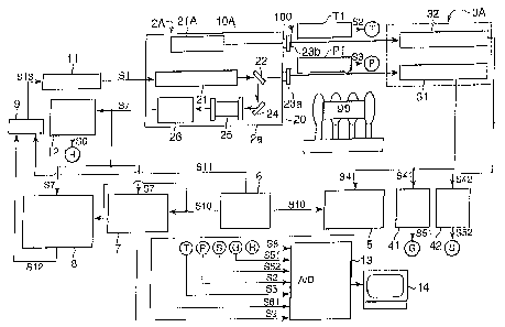
As shown in Fig. 5(a), a gas flux measuring device lOD comprises
the measuring part 2D and control/analyzing part 19D so that signals
are transmitted or received between the measuring part 2D and the
control/analyzing part 19D via a communication cable or
radiotelegraph (not shown). While the gas concentration measuring
device 20 of the wavelength TDLAS type incorporated in the measuring
part 2D has substantially the same construction as the gas
concentration measuring device 10 of the ~~avelength modulation
TDLAS type shown in Fig. 1, in the present embodiment, in order to
enhance the accuracy of the gas concentration measurement, there are
additionally provided a double wavelength modulation mechanism (a
first wavelength modulation waveform generator 61, a second
wavelength modulation waveform generator 62) in the control/analyzing
part 19D and a concentration zero measuring part for monitoring a
concentration zero point (a direct current detector 65c in the
control/analyzing part 19D and a zero reference part 29c in the
38
CA 02536416 2006-02-21
measuring part 2D). It is to be noted that in the respective blocks
shown in Fig. 5(a), reference letters PSD designate a phase sensitive
detector and, following the reference letters PSD, reference letter G
designates a measuring part, reference letter R a reference part,
reference letter Z a background COa measurement and reference letters
FB a wavelength fixing.
Concretely, the measuring part 2D provided on the forest
observation tower 91 comprises a TDLAS optical system unit oscillating
a laser beam as the gas concentration measuring device 20 of the
wavelength TDLAS type, a light receiver (PD-G) 29a receiving the laser
beam that has been transmitted through the measuring region 100 and
an ultrasonic current meter 51.
The measuring part 2D in its entirety is covered by the protective
container 2b. The TDLAS optical system unit 20 (or the wavelength
TDLAS type gas concentration measuring device 20) in its entirety is
covered by the optical system container 2a that is excellent in a
weather resistance for the purpose of enhancing an anti-environment
property. The optical system container 2a is fitted with the optical
v~lindow 23 through which the laser beam is radiated. The light
receiver (PD-G) 29a made by a photodiode is arranged so as to face to
the optical window 23. An opening end of the sampling pipe 9S is
introduced into the measuring part 2D to be positioned between the
light receiver (PD-G) 29a and the optical window 23, so that the intake
gas (the air in the forest 99) is supplied thereinto. In the present
embodiment, a distance L1 from the optical window 23 to the light
39
CA 02536416 2006-02-21
receiver (PD-G) 29a is set to about 2m.
Next, the control/analyzing part 19D provided in the observation
room 90 near the forest observation tower 9I comprises the LD
controller 11 controlling the oscillated laser beam from a semi-
s conductor laser (LD) 28, first wavelength modulation waveform
generator (No. 1-FG) 61 / second wavelength modulation waveform
generator (No. 2-FG) 62 both modulating the laser beam; direct current
detectors (LPF) 65a to 65c functioning as mentioned below, first phase
sensitive detectors (No. 1-PSD-G, Z, R, FB) 63 (63a to 63d)/second
phase sensitive detectors (No. 2-PSD-G, Z, R, FB) 64 (64a to 64d)
functioning as mentioned below, the A/D converter 13 taking all of the
respective signals, the computer 14 (personal computer) analyzing A/D
converted signals so that the COa concentration and C02 flux in the air
are analyzed and recorded and the adder 9 adding together the
modulation signals from the first waveform generator (No. 1-FG) 61 and
second waveform generator (No. 2-FG) 62 and the wavelength fixing
signal from the second phase sensitive detector (No. 2-PSD-FB) 64d and
putting out a signal as an external control signal into the LD control
unit 1 1.
The direct current detectors (LPF) 65a to 65c function to detect
the direct current component out of the received light signals from
respective light receivers (PD-G, PD-R, PD-Z) 29a to 29c and put out
received light strength signals S23, 522, S21. The first phase sensitive
detectors (No. 1-PSD-G, Z, R, FB) 63 (63a to 63d) function, based on
the reference signals from the first wavelength modulation waveform
CA 02536416 2006-02-21
generator 61, to detect only such signals as synchronized with a double
wave frequency component of the modulation frequency from the
respective received Iight signals and put them out. The second phase
sensitive detectors (No. 2-PSD-G, Z, R, FB) 64 (64a to 64d) function,
based on the reference signals from the second wavelength modulation
waveform generator (No. 2-FG) 62, to detect only such signals as
synchronized with the double wave frequency component of the
modulation frequency from the output signals from the first phase
sensitive detectors 63.
Also, in the present embodiment, there are additionally provided
a wavelength sweep waveform generator (FG) 66 sweeping the laser
wavelength around the C02 absorption wavelength and a change-over
switch (SW) 67 changing over the signal therefrom with the laser
wavelength fixing signal.
The measuring part 2D comprises therein the ultrasonic current
meter 51, a semi-conductor type pressure sensor 53 and a temperature
sensor 52. These current meter S I and sensors 52, 53 are provided
near a blow-off port of the sampling pipe 91 and put out a measured
flow velocity signal S 19, measured temperature signal S2 and measured
pressure signal S3, respectively, into the computer 14 as the analyzing
part via the A/D converter 13.
The single semi-conductor laser (LD) 28 can adjust the laser
oscillation wavelength to one of the absorption wavelengths of C02.
The optical system comprises a first half mirror 22a, second half mirror
22b and reflecting mirror 24. The first half mirror 22a transmits a
41
CA 02536416 2006-02-21
portion of the laser beam oscillated from the light source 28 to be
distributed to the optical window 23 so that this laser beam is radiated
toward the light receiver (PD-G) 29a for measuring purpose. At the
same time, the first half mirror 22a reflects a portion of the oscillated
laser beam to be distributed to the second half mirror 22b. The second
half mirror 22b reflects a portion of the distributed Laser beam to be
further distributed to the reference cell 25 and, at the same time,
transmits a portion of the distributed laser beam to be distributed to
the zero reference part (PD-Z) 29c via the reflecting mirror 24. In the
reference cell 25, C02 gas of a predetermined concentration (COa = 1%,
N2 = 99%) is enclosed. The laser beam that has been transmitted
through the reference cell 25 enters the light receiver (PD-R) 29b for
reference purpose so that a received light signal is put out into a direct
current detector (LPF) 65b of the control/analyzing part 19D. The
direct current detector (LPF) 65b removes an alternating current
component as a modulation signal from the received light signal and
puts out a signal S22 thereof into the computer 14.
On the other hand, with the received light signal entering the
direct current detector (LPF) 65c of the control/analyzing part 19D from
the zero reference part (PD-Z) 29c, the direct current detector (LPF) 65c
removes an alternating current component as a modulation signal from
the received light signal and puts out the signal S21 thereof into the
computer 14.
The light receiver (PD-G) 29a for measuring purpose puts out the
2~ received light signal into a direct current detector (LPF) 65a and first
42
CA 02536416 2006-02-21
phase sensitive detector (No. 1-PSD-G) 63a, respectively, of the
control/analyzing part 19D. With the received light signal entering the
direct current detector (LPF) 65a, the direct current detector (LPF) 65a
removes an alternating current component as a modulation signal from
the received light signal and puts out the signal S23 thereof into the
computer 14. Based on the wavelength modulation reference signal
from the first wavelength modulation waveform generator (No. 1-FG) 61,
the first phase sensitive detector (No. 1-PSD-G) 63a detects an even
number order harmonic component of the wavelength modulation signal
added to the laser beam out of the signal put out from the light receiver
29a for measuring purpose and puts out a signal in proportion to the
concentration of the enclosed gas in the reference cell into a second
phase sensitive detector (No. 2-PSD-G) 64a. Also, based on the
wavelength modulation reference signal from the second wavelength
modulation waveform generator (No. 2-FG) 62, a second phase sensitive
detector (No. 2-PSD-G) 64a detects an odd number order harmonic
component of the wavelength modulation signal added to the laser
beam out of the signal put out from the light receiver 29a and puts out
a signal S24 in proportion to the concentration of the enclosed gas in
the reference cell into the computer 14.
In order for the laser oscillation wavelength to be slowly swept at
the absorption spectrum that is natural to the measuring object gas,
the wavelength sweep waveform generator (FG) 66 is constructed such
that a ramp wave of frequency of 0.5 Hz or 0.01 Hz, for example, is
applied to an injection current of the semi-conductor laser element. It
43
CA 02536416 2006-02-21
is to be noted that in case where the changes of the gas concentration
are to be measured for a long time, the sweep of the laser oscillation
wavelength by the wavelength sweep waveform generator 66 is stopped
and the laser oscillation wavelength is locked to a predetermined
wavelength. The wavelength sweep waveform generator 66 puts out a
wavelength sweep signal S28 into the computer 14.
For modulating the laser oscillation wavelength, the two
wavelength modulation waveform generators 61, 62 are constructed
such that sine waves of frequencies different from each other are
doubly applied to the injection current of the semi-conductor laser
element 28. For example, from the one wavelength modulation
waveform generator 61, a sine wave of 10 KHz (f = 10 KHz), for example,
as a first modulation frequency f is applied to the LD controller 11 via
the adder 9 and from the other wavelength modulation waveform
generator 62, a sine wave of 500 Hz (w = 500 Hz = 0.5 KHz), for example,
as a second modulation frequency w is applied to the LD controller 1 1
via the adder 9.
The adder 9 superposes a sweep signal S29 from the wavelength
sweep waveform generator 66, modulation signals S25, S26 of the
different frequencies f, w from the two wavelength modulation waveform
generators 61, 62 and a third order differential demodulation signal
S27 of the frequency 2f + w from the phase sensitive detectors 63a to
63d, 64a to 64d of two steps and the result thereof is applied to the
injection current of the semi-conductor Iaser element.
By the ramp wave having the sweep wavelength being applied to
44
CA 02536416 2006-02-21
the injection current from the wavelength sweep waveform generator 66
as well as by the sine waves of the different frequencies f, w being
doubly applied to the injection current from the wavelength modulation
waveform generators 61, 62, the laser oscillation wavelength is doubly
modulated by the two different frequencies f, w. As the result of this,
the received light signal of the laser beam includes both the modulation
frequencies f, w and harmonic components thereof. Hence, the signals
are demodulated in the frequency of two times, that is, 20 KHz (2f), by
the first phase sensitive detectors 63a to 63d and are then demodulated
in the frequency of two times, that is, 1 KHz (2w), by the second phase
sensitive detectors 64a to 64d. Thus, a fourth order differential signal
(2f + 2w) in which these demodulated signals are superposed is sent to
the computer 14.
Also, the signals demodulated in the frequency of two times, that
is, 20 KHz (2f), by the first phase sensitive detectors 63a to 63d are
demodulated in the frequency w by the second phase sensitive detectors
64a to 64d. Thus, a third order differential signal (2f + w) in which
these demodulated signals are superposed is sent to the adder 9 via the
change-over switch 67. Based on this signal, the laser oscillation
wavelength is applied with a feedback control to the absorption central
wavelength of the measuring object gas.
The wind velocity on the tower 91 is measured by the ultrasonic
current meter S 1 and a wind velocity signal (S) thereof is put out into
the control/analyzing part 19D of the observation room 90. As shown
in Figs. 5(a) and (b), the measuring region 100 includes the air on the
CA 02536416 2006-02-21
tower 91 of a measuring length of 2m (L1 = 2m). Also, the pressure of
the measuring region 100 is measured by a semi-conductor type
pressure sensor 53 and a measured pressure signal S3 thereof is put
out into the observation room 90. The temperature of the measuring
region 100 is measured by a thermocouple (temperature sensor) 52 and
a measured temperature signal S2 thereof is put out into the computer
14. In terms of the pressure or temperature, it is to be noted that, in
place of using the sensors, a measurement by a laser may also be
employed making use of the characteristic of the absorption spectrum
of the measuring object gas.
In order to measure the absorption spectrum, a ramp wave of 0.5
Hz or 0.01 Hz, for example, is applied to the injection current by the
wavelength sweep waveform generator (FG) 66 so that sweeping of the
laser wavelength is slowly carried out. If concentration changes for a
long time are to be measured, the laser wavelength is locked.
In the present Measurement 1, for the purpose of comparison,
conventional measurements are also carried out as a comparison
example 1 such that sampling of the air is done from substantially the
same position as the measuring region of the present invention and the
air is pretreated by the pretreatment device 94 and measured by the
prior art C02 meter 93 so that the measurement result is analyzed by
the eddy correlation method together with the measurement result of
the ultrasonic current meter 51 and, at the same time, the COa flux is
measured.
Fig. 6 is a characteristic diagram showing the result of the
46
CA 02536416 2006-02-21
Measurement 1, wherein the horizontal axis shows the measuring time
and the vertical axis shows the measured COa flux (mg/m2 ~ S). There,
a solid line A1 shows the result of the Measurement 1 according to the
device of the present invention and a broken line B 1 shows the result of
the comparison example 1 measured by a conventional device using the
sampling method.
The results of both of the measurements are substantially the
same, by which it is verified that the C02 flux measurement according
to the present invention is feasible. Moreover, in circumstances, such
as immediately after the sunrise or immediately after the sunset, where
the momentum flux largely changes from minus to plus by change-over
of the photosynthesis/breathe of plants, while the measurement result
of the present Measurement 1 (the characteristic line A1) clearly
catches these changes, the measurement result of the conventional art
(the characteristic line B1) does not necessarily catch such clear
changes. This is considered because of the response delay of the prior
art COa meter 93 due to a dilution effect or the like. In this way, in the
conventional device, quick changes in the measuring region cannot be
sufficiently grasped and there is a tendency that the actual flux
quantity is underestimated. On the contrary, in the C02 flux
measurement by the device of the present invention, quick changes in
the measuring region can be precisely grasped and the feasibility
thereof is verified.
(Measurement 2)
Next, as Measurement 2, an example of measuring the regional
47
CA 02536416 2006-02-21
COa flux between two forest observation towers using a combination of
the TD LAS regional gas concentration measuring device and the
scintillation method according to the present invention as still another
embodiment will be described with reference to Figs. 7(a) and (b). It is
to be noted that as to the parts and components of the present
embodiment substantially the same as those of the above described
embodiments, descriptions thereof will be omitted.
In the present Measurement 2, in order to verify the regional gas
flux measurement according to the present invention, a wavelength
TDLAS type gas concentration measuring device and a scintillation
method type momentum flux measuring device, combined together, are
provided on the forest observation towers and the result of
measurements by these two devices are analyzed based on the MOS law,
so that the regional COa flux between the forest observation towers is
measured.
Figs. 7(a) and (b) show a device system used for the present
Measurement 2. Construction of a wavelength TDLAS type gas
concentration measuring device system 2E including 19E is
substantially the same as the device system 2D including 19D used for
the Measurement 1 shown in Figs. 5(a) and (b). Also, a
control/analyzing part 19E provided in the observation room 90 is
substantially the same as the control/analyzing part 19D of the
Measurement 1 shown in Figs. 5(a) and (b). However, in the system of
the present Measurement 2, because of the regional gas concentration
measurement, a measuring length L2 is set to a very long distance such
48
CA 02536416 2006-02-21
that L2 = 81 m which equals the distance between two forest
observation towers 91, 92. It is to be noted that in the respective
blocks shown in Fig. 7(a), reference letters FG designate a waveform
generator, reference letters PSD a phase sensitive detector, reference
letter G a measuring part, reference letter R a reference part, reference
letter Z a background COz measurement, reference letters FB a
wavelength fixing and reference letter S a scintillation measuring part.
The same applies also to the below mentioned systems shown in Figs. 9,
11 and 13.
Concretely, a light source part 2E provided on a first forest
observation tower 91 comprises a TDLAS optical system unit 20 having
substantially the same construction as the unit 20 of the above
Measurement 1 as well as comprises the scintillation measuring unit 70
shown in Figs. 15C and D. From the light source part 2E, a reference
part received light signal S22 and zero part received light signal S21 as
well as a strength modulation reference signal S24 of the scintillation
measuring unit 70 are put out into the control/analyzing part 19E of
the observation room 90 and, at the same time, an LD control signal
S21 is put out from the control/analyzing part 19E of the observation
room 90 into the TDLAS optical system unit 20. In the scintillation
measuring unit 70, two scintillation measuring Laser oscillators 71, 72
are mounted so that an oscillated laser is radiated to the measuring
region 100 through optical windows 73a, 73b, respectively, to be
received by a light receiving part 3E provided on a second forest
observation tower 92.
49
CA 02536416 2006-02-21
In the present embodiment, a semi-conductor type pressure
sensor 53 and a thermocouple (temperature sensor) 52 are provided on
the first forest observation tower 91 and measurement values thereof
are representatively used as the pressure and temperature of the
measuring region 100. But using characteristics of the absorption
spectrum of the measuring object gas, the average pressure and
average temperature of the measuring region 100 may also be measured
by a laser.
Next, the light receiving part 3E provided on the second forest
observation tower 92 comprises a light receiver (PD-G) 35 receiving a
laser beam radiated from the TDLAS optical system unit 20 of the light
source part 2E provided on the first forest observation tower 91 and
transmitted through the atmospheric air and two light receivers (PD-S 1,
PD-S2) 33, 34 receiving the laser beams radiated from the scintillation
measuring unit 70. Respective received light signals S23, S 191, S 192
(G, S1, S2) thereof are put out into the control/analyzing part 19E of
the observation room 90 for analysis.
In the present embodiment, a signal transmission (shown by ~
mark in Fig. 7(a)] from the light source part 2E and light receiving part
3E on the towers 91, 92 to the observation room 90 is carried out by
electric wiring cables using usual metal wires. However, the present
invention is not limited thereto but, in order to correspond to cases
where the measuring length is further elongated, a signal transmission
method by an optical fiber system or wireless system in which
communication facilities are easily installed may also be employed.
CA 02536416 2006-02-21
Fig. 8 is a characteristic diagram showing the result of the
Measurement 2, wherein the horizontal axis shows the measuring time
and the vertical axis shows the measured C02 flux (mg/m2 - S). There,
a solid line A2 shows the result of the Measurement 2 according to the
device of the present invention, a broken line B2 shows the result of a
comparison example 1 in which the concentration measurement by a
prior art C02 meter and the flux measurement by the ultrasonic current
meter on the first observation tower 91 are combined and a two-dot
chain line C2 shows the result of a comparison example 2 in which the
concentration measurement by a prior art C02 meter and the flux
measurement by an ultrasonic current meter on the second observation
tower 92 are combined. As clearly understood from the figure, the
result of the present Measurement 2 (the characteristic line A2) forms a
change curve that is smoother than the results of the comparison
examples 1, 2 (the characteristic lines B2, C2). This is because of the
feature of the present invention in that there is no obstruction (or no
external disturbance) at all between the light source part and the light
receiving part. On the other hand, in the measurement results of the
comparison examples using the prior art, there are generated many
notches in the change curves. This is because of the prior art problem
in that there are provided many measuring devices, creating
interferences with each other, in the measuring region and the
existence itself of such measuring devices becomes the cause of the
external disturbances.
While it is difficult to verify the measurement result of the
51
CA 02536416 2006-02-21
regional C02 flux according to the present invention (the characteristic
line A2) directly based on the measuring results of the comparison
examples using the prior art (the characteristic lines B2, C2), the
measurement result of the present invention approximately accords
with the result of the measurements carried out on each of the towers
using the prior art. Thus, it is verified that the present invention is
appropriate for real time measurements of the regional C02 flux.
(Measurement 3)
Next, as Measurement 3, an example of measuring the regional
COz flux between two forest observation towers using a semi-conductor
laser type gas flux measuring device according to the present invention
as still another embodiment will be described with reference to Figs.
9(a) and (b). It is to be noted that as to the parts and components of
the present embodiment substantially the same as those of the above
described embodiments, descriptions thereof will be omitted.
In the present Measurement 3, in order to verify the regional gas
flux measurement according to the present invention, a semi-conductor
laser type gas flux measuring device system 2F including 3F as a single
unit of the wavelength TDLAS type gas concentration measuring device
added with a scintillation method function is provided on the forest
observation towers 91, 92 and the result of measurements thereof are
analyzed based on the MOS law, so that the regional COa flux between
the forest observation towers 91, 92 is measured. It is to be noted that
in the present Measurement 3 also, like in the Measurement 2, the
measuring length L2 is set to 81 m that equals the distance between the
52
CA 02536416 2006-02-21
towers 91, 92.
Figs. 9(a) and (b) show a device system used for the present
Measurement 3. While the construction of a wavelength TDLAS type
gas concentration measuring device system 2F including 3F is
substantially the same as the representative device construction shown
in Fig. 2, like in the Measurements 1, 2, in order to enhance the
measuring sensitivity and measuring stability, a double wavelength
modulation mechanism and zero point measuring mechanism are
additionally provided. Also, a control/analyzing part 19F provided in
the observation room 90 is substantially the same as the
control/analyzing part 19D of the Measurement 2 shown in Figs. 7(a)
and (b) .
Concretely, a light source part 2F provided on the first forest
observation tower 91 is constructed such that the basic construction of
the TDLAS optical system unit 20 of the Measurements l, 2 is provided
with a laser oscillator (LD2) 28b separately from a light source (LD 1)
28a for gas concentration measuring purpose. From the light source
part 2F, a reference part received light signal S22 and zero part
received light signal S21 are put out into the control/analyzing part
19F of the observation room 90 and, at the same time, control signals
S 1 a, S 1 b are put out from the control/ analyzing part 19F of the
observation room 90 into the respective devices 28a, 28b of the light
source part 2F. Also, in the present embodiment, the semi-conductor
type pressure sensor 53 and the thermocouple (temperature sensor) 52
are provided on the first forest observation tower 91 and measurement
53
CA 02536416 2006-02-21
values thereof are representatively used as the pressure and
temperature of the measuring region 100. But using characteristics of
the absorption spectrum of the measuring object gas, the average
pressure and average temperature of the measuring region 100 may
also be measured by a laser.
Next, the light receiving part 3F provided on the second forest
observation tower 92 comprises light receivers (PD-G, PD-S) 29a, 29b
receiving a laser beam radiated from the optical unit 20 and
transmitted through the air betc~~een the two towers 91, 92. Respective
received light signals S20, S23 thereof are put out into the
control/analyzing part 19F of the observation room 90 for analysis. It
is to be noted that while in the present embodiment, a signal
transmission [shown by * mark in Fig. 9(a)) thereof is carried out by
usual electric wiring cables, in order to correspond to cases where the
measuring length is further elongated, a signal transmission method by
an optical fiber system or wireless system in which communication
facilities are easily installed may also be employed.
Fig. 10 is a characteristic diagram showing the result of the
Measurement 3, wherein the horizontal axis shoes the measuring time
and the vertical axis shows the measured C02 flux (mg/m2 ~ S). There,
a solid line A3 shows the result of the Measurement 3 according to the
device of the present invention, a broken line B3 shows the result of a
comparison example 1 in which the concentration measurement by a
prior art C02 meter and the flux measurement by an ultrasonic current
meter on the first observation tower 91 are combined and a two-dot
54
CA 02536416 2006-02-21
chain line C3 shows the result of a comparison example 2 in which the
concentration measurement by a prior art COa meter and the flux
measurement by an ultrasonic current meter on the second observation
tower 92 are combined. As clearly understood from the figure, the
result of the present Measurement 3 (the characteristic line A3) forms a
change curve that is smoother than the results of the comparison
examples 1, 2 (the characteristic lines B3, C3). This is because of the
feature of the present invention in that there is no obstruction (or no
external disturbance) at all between the light source part and the light
receiving part. On the other hand, in the measurement results of the
comparison examples using the prior art, there are generated many
notches in the change curves. This is because of the prior art problem
in that there are provided many measuring devices, creating
interferences with each other, in the measuring region and the
existence itself of such measurement devices becomes the cause of the
external disturbances.
V~lhile it is difficult to verify the measurement result of the
regional C02 flux according to the present invention (the characteristic
line A3) directly based on the measurement results of the comparison
examples using the prior art (the characteristic lines B3, C3), the
measurement result of the present invention approximately accords
with the result of the measurements carried out on each of the towers
using the prior art. Thus, it is verified that the present invention is
appropriate for real time measurements of the regional C02 flux.
(Measurement 4)
~5
CA 02536416 2006-02-21
Next, as Measurement 4, an example of measuring the regional
C02 flux between two forest observation towers using a semi-conductor
laser type gas flux measuring device according to the present invention
as still another embodiment will be described with reference to Figs.
l I(a) and (b). It is to be noted that as to the parts and components of
the present embodiment substantially the same as those of the above
described embodiments, descriptions thereof will be omitted.
In the present Measurement 4, in order to verify the regional gas
flux measurement according to the present invention, a semi-conductor
laser type gas flux measuring device system 2G including 3G as a single
unit of the wavelength TDLAS type gas concentration measuring device
added with a scintillation method function is provided on the forest
observation towers 91, 92 and the result of measurements thereof are
analyzed based on the MOS law, so that the regional C02 flux between
the forest observation towers 91, 92 is measured. It is to be noted that
in the present Measurement 4 also, like in the above-mentioned
Measurement 2, the measuring length L2 is set to 81m that equals the
distance between the towers 91, 92.
Figs. I 1 (a) and (b) show a device system used for the present
Measurement 4. While the construction of the wavelength TDLAS type
gas concentration measuring device system is substantially the same as
the representative device construction shown in Fig. 3, like in the
Measurements 1, 2, in order to enhance the measuring sensitivity and
measuring stability, a double wavelength modulation mechanism and
zero point measuring mechanism are additionally provided.
~6
CA 02536416 2006-02-21
Concretely, a light source part 2G provided on the first forest
observation tower 91 is constructed such that the basic construction of
the TDLAS optical system unit of the Measurements 1, 2 is provided
with a polarization plane rotating device 27G distributing a laser beam
for measuring purpose to two portions and, while rotating a laser
polarization plane of one of the two portions by an angle of 90°,
oscillating the laser beam toward the measuring region. Thereby, the
reference part received light signal S22 and zero part received light
signal S21 are put out into a control/analyzing part 19G of the
ZO observation room 90 and, at the same time, the LD control signal S 1 is
put out from the control/analyzing part 19G of the observation room 90
into the TDLAS optical system unit 20. The polarization plane rotating
device 27G comprises a Faraday rotator, so that the polarization plane
of the laser beam oscillated from the semi-conductor laser beam source
(LD) 28 is rotated and the laser polarization plane is converted between
the vertical polarization and the horizontal polarization.
In the present embodiment, the semi-conductor type pressure
sensor 53 and the thermocouple (temperature sensor) 52 are provided
on the first forest observation tower 91 and measurement values
thereof are representatively used as the pressure and temperature of
the measuring region 100. But using characteristics of the absorption
spectrum of the measuring object gas, the average pressure and
average temperature of the measuring region 100 may also be measured
by a laser.
Next, the light receiving part 3G provided on the second forest
57
CA 02536416 2006-02-21
observation tower 92 comprises the two light receivers (PD-G, PD-S)
29a, 29b receiving the two laser beams radiated from the optical unit
20 and transmitted through the air between the two towers 91, 92.
The respective received light signals 520, S23 thereof are put out into
the control/analyzing part 19G of the observation room 90 for analysis.
It is to be noted that while in the present embodiment, a signal
transmission [shown by * mark in Fig. 1 1 (a)] thereof is carried out by
usual electric wiring cables, in order to correspond to cases where the
measuring length is further elongated, a signal transmission method by
an optical fiber system or wireless system in which communication
facilities are easily installed may also be employed. Further, the
control/ analyzing part 19G provided in the observation room 90 is
substantially the same as that of the Measurement 2 shown in Figs.
7(a) and (b).
Fig. 12 is a characteristic diagram showing the result of the
Measurement 4, wherein the horizontal axis shows the measuring time
and the vertical axis shows the measured COa flux (mg/m2 ~ S). There,
a solid line A4 shows the result of the Measurement 4 according to the
device of the present invention, a broken line B4 shows the result of a
comparison example 1 in which the concentration measurement by a
prior art C02 meter and the flux measurement by an ultrasonic current
meter on the first observation tower 91 are combined and a two-dot
chain line C4 shows the result of a comparison example 2 in which the
concentration measurement by a prior art C02 meter and the flux
measurement by an ultrasonic current meter on the second observation
58
CA 02536416 2006-02-21
tower 92 are combined.
While it is difficult to verify the measurement result of the
regional COz flux according to the present invention directly based on
the measuring results using the prior art, the measurement result of
the present invention approximately accords with the result of the
measurements carried out on each of the towers using the prior art.
Thus, it is verified that the present invention is appropriate for real
time measurements of the regional COa flux.
(Measurement 5)
Next, as Measurement 5, an example of measuring the regional
COa flux between two forest observation towers using a semi-conductor
laser type gas flux measuring device according to the present invention
as still another embodiment will be described with reference to Figs.
13(a) and (b). It is to be noted that as to the parts and components of
the present embodiment substantially the same as those of the above
described embodiments, descriptions thereof will be omitted.
In the present Measurement 5, in order to verify the regional gas
flux measurement according to the present invention, a semi-conductor
laser type gas flux measuring device system 2H including 3H as a single
unit of the wavelength TDLAS type gas concentration measuring device
added with a scintillation method function is provided on the forest
observation towers 91, 92 and the result of measurements thereof are
analyzed based on the MOS law, so that the regional COa flux between
the forest observation towers 91, 92 is measured. It is to be noted that
in the present Measurement S also, like in the above-mentioned
59
CA 02536416 2006-02-21
Measurement 2, the measuring length L2 is set to 81m that equals the
distance between the towers 91, 92.
Figs. 13(a) and (b) show a device system used for the present
Measurement 5. As the polarization plane modulation frequency is
sufficiently lower as compared with the wavelength modulation
frequency, while the construction of the wavelength TDLAS type gas
concentration measuring device system is substantially the same as the
representative device construction shown in Fig. 4, like in the
Measurements 1, 2, in order to enhance the measuring sensitivity and
measuring stability, a double wavelength modulation mechanism and
zero point measuring mechanism are additionally provided.
Concretely, a light source part 2H provided on the first forest
observation tower 91 is constructed such that the basic construction of
the TDLAS optical system unit of the Measurements 1, 2 is provided
with a polarization plane modulator 59 providing a polarization plane
modulating function and the optical unit 20 added with a modulation
controller 58 therefor. Thereby, the reference part received light signal
S22 and zero part received light signal S21 as well as a polarization
plane modulation reference signal S37 are put out into a
control/analyzing part 19H of the observation room 90 and, at the same
time, the LD control signal S 1 is put out from the control/ analyzing
part 19H of the observation room 90 into the optical system unit 20.
In the present embodiment, the semi-conductor type pressure sensor
53 and the thermocouple (temperature sensor) 52 are provided on the
27 first forest observation tower 91 and measurement values thereof are
CA 02536416 2006-02-21
representatively used as the pressure and temperature of the
measuring region 100. But using characteristics of the absorption
spectrum of the measuring object gas, the average pressure and
average temperature of the measuring region 100 may also be measured
by a laser.
As compared with the control/analyzing part 19E of the
Measurement 2 shown in Fig. 7(a), the control/analyzing part 19H
provided in the observation room 90 is additionally provided with a
third phase sensitive detector (No. 3-PSD-G) 64e detecting, based on
the polarization modulation reference signal S37, a signal component
synchronized with the modulation out of the signal put out from the
second phase sensitive detector (No. 2- PSD-G) 64a, a phase sensitive
detector (No. 1-PD-S) 64f taking out a received light strength signal of
the vertically polarized laser or horizontally polarized laser out of the
PD-G received light signal and a phase shifter 68 putting out a signal
S36 for shifting the phase of the polarization plane modulation
reference signal S37 and, instead thereof, the direct current component
detector for the received light strength signal is omitted.
The light receiving part 3H provided on the second forest
observation tower 92 comprises a light receiver (PD-G) 29 receiving a
laser beam radiated from the optical unit 20 and transmitted through
the air between the two towers 91, 92. A received light signal S22
thereof is put out into the control/analyzing part 19H of the
observation room 90 for analysis. It is to be noted that while in the
present embodiment, a signal transmission [shown by * mark in Fig.
61
CA 02536416 2006-02-21
13(a)] thereof is carried out by usual electric wiring cables, in order to
correspond to cases where the measuring length is further elongated, a
signal transmission method by an optical fiber system or wireless
system in which communication facilities are easily installed may also
be employed.
Fig. 14 is a characteristic diagram showing the result of the
Measurement 5, wherein the horizontal axis shows the measuring time
and the vertical axis shows the measured COa flux (mg/m2 ~ S). There,
a solid line A5 shows the result of the Measurement 5 according to the
device of the present invention, a broken line B5 shows the result of a
comparison example 1 in which the concentration measurement by a
prior art C02 meter and the flux measurement by an ultrasonic current
meter on the first observation tower 91 are combined and a two-dot
chain line C5 shows the result of a comparison example 2 in which the
concentration measurement by a prior art C02 meter and the flux
measurement by an ultrasonic current meter on the second observation
tower 92 are combined.
While it is difficult to verify the measurement result of the
regional C02 flux according to the present invention directly based on
the measuring results of the comparison examples using the prior art,
the measurement result of the present invention approximately accords
with the result of the measurements carried out on each of the towers
using the prior art. Thus, it is verified that the present invention is
appropriate for real time measurements of the regional C02 flux.
62
CA 02536416 2006-02-21
INDUSTRIAL APPLICABILITY
The gas flux measuring device according to the present invention
is appropriate to be used for monitoring an existing quantity of regional
greenhouse gases (GHG), that is, for example, for assessing a COa
absorption quantity by a forest, carrying out an environment
investigation, such as an investigation of generation quantity of GHG
coming out of the ground, or for detecting a gas leakage from COa
underground disposal plants, gas storage facilities, pipelines, etc.
63