Note: Descriptions are shown in the official language in which they were submitted.
CA 02536446 2006-02-14
THE USE OF LAMB WAVES IN CEMENT BOND LOGGING
1. Field of the Invention
The present invention relates to a method and apparatus to evaluate
the integrity of bonds that adhere wellbore casing to a wellbore. The present
invention further relates to a method and apparatus capable of evaluating
bond integrity of bonding cements of different densities. Yet even more
specifically, the present invention relates to a method and apparatus capable
of evaluating cement bond integrity that can distinguish a casing bonded with
a light weight cement from a casing surrounded with a micro-annulus fluid.
2. Description of Related Art
Hydrocarbon producing wellbores comprise casing 8 set within the
wellbore 5, where the casing 8 is bonded to the wellbore by adding cement 9
within the annulus formed between the outer diameter of the casing 8 and the
inner diameter of the wellbore 5. The cement bond not only adheres the
casing 8 within the wellbore 5, but also serves to isolate adjacent zones (Z1
and Z2) within the formation 18 from one another. Isolating adjacent zones
can be important when one of the zones contains oil or gas and the other
zone includes a non-hydrocarbon fluid such as water. Should the cement 9
surrounding the casing 8 be defective and fail to provide isolation of the
adjacent zones, water or other undesirable fluid can migrate into the
hydrocarbon producing zone thus diluting or contaminating the hydrocarbons
within the producing zone.
To detect possible defective cement bonds, downhole tools 14 have
been developed for analyzing the integrity of the cement 9 bonding the casing
8 to the wellbore 5. Typically these downhole tools 14 are disposed within the
wellbore 5 suspended on a wireline 10 via a pulley 12. The downhole tools 14
also usually include transducers 16 disposed on their outer surface capable.
of emitting acoustic waves into the casing 8 and recording the attenuation of
the acoustic waves as they travel, or propagate, across the surface of the
casing 8. The recorded attenuation can be transmitted to the surface through
the wireline 10 where it can be analyzed. By analyzing the attenuation of the
CA 02536446 2006-02-14
-2-
acoustic wave, the efficacy and integrity of the cement bond can be
evaluated.
The amount of attenuation however can depend on how the acoustic
wave is polarized and the coupling condition between the casing 8 and the
cement 9. Typical downhole tools 14 having acoustic wave transducers 16
generate acoustic waves that are polarized perpendicular to the surface of the
casing 8. Such waves are referred to as compression/shear or P-SV waves
since the particle motion direction of either the compressional (P) or,the
shear
(S) component of the acoustic wave is in a vertical (V) plane perpendicular to
the casing 8. The attenuation of the acoustic wave as it propagates along the
surface of the casing 8 depends the condition of the cement bond and is also
dependent on the type of cement 9 disposed between the casing 8 and the
formation 18. More specifically, as the acoustic wave propagates along the
length of the casing 8, the wave loses, or leaks, energy into the formation 18
through the cement bond - it is this energy loss that produces the attenuation
of the acoustic wave. Conversely, when the casing 8 is not bonded, a
condition also referred to as "free pipe," the micro-annulus fluid behind the
casing does not provide for any shear coupling between the casing 8 and the
formation 18. Loss of shear coupling significantly reduces the compressional
coupling between the casing 8 and the formation 18. This result occurs since
fluid has no shear modulus as well as a much lower bulk modulus in relation
to cement. Because of these physical characteristics of fluid, the entire SV
component of the P-SV wave and a large portion of the P component of the P-
SV wave do not propagate outside of the casing 8 and thus experience a
much reduced attenuation.
Reduced attenuation of an acoustic wave is not limited to situations
where the casing 8 is surrounded by fluid, but the presence of some types of
cement can also significantly reduce acoustic wave attenuation. For example,
light weight cement (LWC), or cement having a density less than
approximately 12 Ibs/gal can reduce acoustic wave attenuation. Light weight
cement has a shear modulus, thus light weight cement can maintain shear
coupling between the casing 8 and the formation 18. However, the density of
light weight cement is not substantially greater than the density of many
fluids
CA 02536446 2006-02-14
-3-
(such as water), thus the attenuation of some acoustic waves, especially P-
SV waves, is diminished when encountering casing 8 surrounded by a light
weight cement. The result of this reduced attenuation is a decreased ability
to
detect the difference between fluid and light weight cement as well as a
diminished capacity to detect poor cement bonds in light weight cement when
using traditional acoustic methods.
Therefore, there exists a need for a device and method to conduct
cement bond logs within a casing, where the device and method is capable of
differentiating between fluid that surrounds a casing and light weight cement
bonding a casing.
BRIEF SUMMARY OF THE INVENTION
The present invention in one aspect includes a method of evaluating a
casing bond disposed between a casing and a wellbore comprising inducing a
Lamb wave into the casing, monitoring the Lamb wave, and estimating a
characteristic of the casing bond based on the monitoring.
The Lamb wave can be induced with a transmitting transducer, or a
transmitting transducer combined with a receiving transducer. The Lamb
wave can be monitored with a receiving transducer. The transmitting
transducer can be an EMAT, a piezoelectric device, or a wedge transducer.
The receiving transducer can be an EMAT and a piezoelectric device.
The step of estimating a characteristic of the casing bond can involve
estimating the quality of the casing bond, estimating the integrity of cement
forming the casing bond, identifying the presence of microannuluses within
the casing bond, as well as estimating the thickness of the casing bond. The
type of casing bond evaluated can include regular cement, light weight
cement, and free pipe.
An alternative method of the present invention involves evaluating a
casing bond disposed between a casing and a wellbore comprising, inserting
a downhole tool within the casing, inducing a Lamb wave in the casing with
the downhole tool, monitoring the Lamb wave, and estimating a characteristic
of the cement based on an evaluation of the Lamb wave.
CA 02536446 2006-02-14
-4-
The tool of this method of the present invention comprises at least one
transmitting transducer capable of inducing the Lamb wave and at least one
receiving transducer capable of monitoring the Lamb wave. The step of
estimating a characteristic of the casing bond of this method can include
estimating the quality of the casing bond, estimating the integrity of cement
forming the casing bond, identifying the presence of microannuluses within
the casing bond, and estimating the thickness of the casing bond. The casing
bond considered with this method includes regular cement, light weight
cement, and free pipe.
The present invention in another aspect includes an evaluation tool
formed for insertion within a wellbore comprising, a body formed for insertion
within the casing of the wellbore, and at least one transducer associated with
the body. The transducer of the evaluation tool induces a Lamb wave within
the casing.
The transducer of the evaluation tool can be a piezoelectric device, a
wedge transducer and an EMAT. Further, the evaluation tool can further
comprise a receiving transducer and a transmitting transducer.
Accordingly, one of the advantages provided by the present invention
is the ability to conduct cement bond logs within a casing while producing
accurate bond log results that distinguish between fluid and light-weight
cement surrounding the casing. The present invention is also capable of
providing improved resolution of cement bond logs in regular cement as
compared to convention methods using P-wave attenuation.
BRIEF DESCRIPTION OF THE SEVERAL VIEWS OF THE DRAWING.
Figure 1 depicts a partial cross section of prior art downhole cement
bond log tool disposed within a wellbore.
Figure 2a illustrates a symmetric Lamb wave propagating through a
plate.
Figure 2b illustrates an antisymmetric Lamb wave propagating through
a plate.
Figure 3 depicts a cross sectional view of a portion of casing bonded to
a formation with a pair of transducers.
CA 02536446 2006-02-14
-5-
Figure 4 depicts a cross sectional view of a portion of casing bonded to
a formation with a pair of transducers, where the bond contains defects.
Figure 5 is a schematic representation of an EMAT device.
Figure 6 depicts a Lamb wave dispersion curve.
DETAILED DESCRIPTION OF THE INVENTION
The present invention includes a method and apparatus useful in
determining characteristics of a casing bond disposed between a casing and
a wellbore. The characteristics of the casing bond include the quality of the
casing bond, the integrity of the cement that comprises the bond, the type of
cement, and the thickness of the casing bond. The method generally involves
inducing an acoustic wave in the casing proximate to the location where the
casing bond is to be evaluated. The acoustic wave propagating within the
casing can then be monitored to estimate characteristics of the casing bond.
It is believed it is well within the scope of those skilled in the art to
ascertain
casing bond characteristics based on the monitoring of the induced acoustic
wave, furthermore, this can be accomplished without undue experimentation.
Lamb waves are complex vibrational waves that travel through the
entire thickness of a material. While different modes of waveforms are
possible with Lamb waves, two of the most common types of Lamb waves are
symmetric and anti-symmetric. With reference now to Figures 2a and 2b, an
example of a symmetric Lamb wave and an anti-symmetric Lamb wave are
illustrated propagating along a plate. In Figure 2a a symmetric Lamb wave is
demonstrated, here particle movement within the plate undergoes both
compression and rarefaction as the wave passes along the plate. The
compression and rarefaction particle movement of the symmetric Lamb wave
within the plate is shown primarily in the vertical direction. The
antisymmetric
Lamb wave of Figure 2b is a longitudinal shear wave that is vertically
polarized such that the particle movement is also perpendicular to the plane
of
the plate. However the particle movement of the antisymmetric Lamb wave is
generally in the same direction and thus does not experience the compression
and rarefaction of the symmetric Lamb wave. The particular Lamb wave
modes preferably are induced one at a time and at different excitation
CA 02536446 2006-02-14
-6-
frequencies. As is well known, the Lamb wave frequency is dependent upon
the thickness of the medium in which the Lamb wave is induced, the Lamb
wave wavelength, and properties of the medium. This physical dependency is
illustrated by the Lamb wave dispersion curves provided in Figure 6. These
curves depict the physical conditions necessary for a Lamb wave to effectively
propagate through a medium. In Figure 6, b is the medium thickness, a is
2rrl~I, w is Zaf, where a denotes wavelength and f denotes frequency, and Vs
is the velocity of the shear wave.
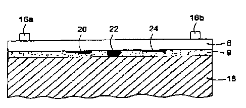
With reference now to Figure 3, wherein is illustrated a partial cross
section of a section of casing 8 attached to adjoining formation 18 with
cement 9. Disposed on the inner diameter of the casing 8 are first and
second transducers (16a, 16b). These transducers (16a, 16b) can both be
capable of transmitting a signal, receiving a signal, or both. The signal
considered for the present invention includes acoustic waves that are not only
Lamb waves, but also Raleigh waves, compressional waves, shear waves,
transversely polarized shear waves, as well as combinations of these
waveforms.
For example, the first transducer 16a could produce an acoustic signal
propagating along the casing 8 towards the second transducer 16b. As noted
above, many acoustic waves used in bond logging operations may be
adequate when dealing with traditional cements, but do not couple well into
light weight cements. Thus these waves will have diminished wave
attenuation along the casing 8 when the casing is bounded by a light weight
cement. In contrast, it has been discovered that Lamb waves can couple well
into light weight cements and thus Lamb waves will experience measurable
attenuation when induced in casing 8 surrounded by light weight cement.
Therefore Lamb waves are well suited for use in the analysis of cement bonds
comprised of regular or light weight cement.
Furthermore, propagating Lamb waves into the bond can also help
detect defects therein, such as the presence of a microannulus 20 or water
22, as well as a poor bond 24. As noted above, Lamb waves have the
capability to couple into light weight cements, but will not couple into bond
defects. As such, the presence of any of these defects disposed between a
CA 02536446 2006-02-14
-7-
transmitting and a receiving transducer can be discovered by monitoring the
resulting attenuation of the Lamb wave propagating across the defect. It is
well within the capabilities of those skilled in the art to study monitored
attenuation results in order to detect the presence of bond defects. It should
be pointed out that the transducer in question can comprise two or more
transducers (16a, 16b) as shown in Figures 3 and 4, but could also comprise
a single transducer capable of transmitting and receiving an acoustic signal.
Analysis of a Lamb wave's attenuation induced within casing 8 can
reveal not only cement characteristics, but also the presence of cement
surrounding the casing 8. Also measurable in this manner is the quality of a
casing bond and the integrity of cement forming a casing bond. Skilled
practitioners are further capable of determining a dimension of the area that
is
formed between the casing 8 and the surrounding formation 18. Values for
other cement or casing bond characteristics that can be similarly derived
include density, compressive strength, tensile strength, mechanical elastic
properties, Young's Modulus, Poisson's ratio, and porosity.
The transducers 16 considered for use with the present invention
include without limitation, piezoelectric devices, electromagnetic acoustic
transmitters (EMAT), and wedge type transducers. The principles of EMAT
operation involve placing a wire near the surface of an electrically
conducting
object (magnetic or non-magnetic) and flowing current through the wire. This
configuration induces eddy currents in the object by electromagnetic
induction (based on electromagnetic skin effect). In the presence of a static
magnetic field (B) these induced eddy currents (J) experience Lorenz forces
(f) given by vector product of those two fields:
f=JXB (1)
Through a variety of interactions, these Lorenz forces are transmitted
into the object and serve as a source of acoustic waves. Depending on the
mutual orientation of the fields one can use EMAT to generate shear waves
or Lamb waves in casing. With reference now to Figure 5 a schematical view
of an EMAT with associated magnetic fields (A~, ASH) is shown. In this
simplified illustration of an EMAT 30 a wire 32 is shown formed into a series
of loops 34. The EMAT 30 is in electrical communication with a current
CA 02536446 2006-02-14
source (not shown) that provides a current i to the wire 32. Applying the
static magnetic field A~ when the EMAT 30 is disposed proximate to an
object, such as the inner diameter of a section of casing 8, will in turn
induce
a Lamb wave within the casing 8. Similarly, if the static magnetic ASH field
is
applied to a section of casing 8, a shear wave can be induced within the
casing 8.
As is known in the art, the wavelength of Lamb waves produced by
EMAT devices is dependent upon the width W of the coil loops 34 within the
EMAT 30. Typically there is a one to one relationship between the width W of
the coil loop 34 and the wavelength ~1 of the Lamb wave produced by the
EMAT 30. Thus the Lamb wave wavelength produced by a specific EMAT
can be controlled by controlling the width W of the coil loop 34.
The present invention described herein, therefore, is well adapted to
carry out the objects and attain the ends and advantages mentioned, as well
as others inherent therein. While a presently preferred embodiment of the
invention has been given for purposes of disclosure, numerous changes exist
in the details of procedures for accomplishing the desired results. These and
other similar modifications will readily suggest themselves to those skilled
in
the art, and are intended to be encompassed within the spirit of the present
invention disclosed herein and the scope of the appended claims.