Note: Descriptions are shown in the official language in which they were submitted.
CA 02537011 2006-02-20
Dispenser for media
The invention relates to a dispenser for media having a medium
reservoir, an applicator having at least one discharge opening, a fin-
ger rest, which can be manually subjected to force, and a pump hav-
ing at least two pump parts which are axially movable relative to
each other.
Such dispensers are used, above all, for liquids, suspensions,
pastes and foams and serve for the dosed discharge of these me
dia. In the medical field, such dispensers are also used, inter alia,
for nasal applications, in which the applicator is realized such that it
can be inserted in the nose so as to deliver liquids or suspensions
therein.
In the prior art, for example in DE 19940234 A1, primarily such dis-
pensers of the generic type are known in which the applicator and
the finger rest are realized in one piece, so that a relative movement
of the finger rest relative to the medium reservoir also constitutes, at
the same time, a relative movement of the applicator relative to the
medium reservoir. These dispensers are usually operated with one
hand, the medium reservoir of the dispenser being clasped with the
hand and held stationary relative to the particular body part, for ex-
ample the nose, while the finger rest is operated with one or two fin-
gers. A perceived drawback with this is that, during the discharge
operation, the applicator with the discharge opening departs from its
original position relative to the particular body part, or the discharge
operation is triggered following the departure of the applicator from
its original position. In the case of a nasal application, this results,
for example, in the nose applicator being withdrawn from the nose,
which adversely affects the delivery of the medium. Although this
can be offset by readjustment of the medium reservoir, this is diffi-
CA 02537011 2006-02-20
2
cult from the motory aspect and reduces the convenience of use
of the dispenser.
The object of the invention is therefore to provide a media dispenser
of the type stated in the introduction, which allows greater conven-
fence of use compared with the prior art.
This object is achieved by the applicator being fixedly connected to
the medium reservoir and the finger rest being axially movable rela-
tive to the medium reservoir and the applicator between a first, un-
pressed operating end position and a second, pressed operating
end position.
In such a dispenser according to the invention, the applicator and
the media reservoir form a, during use, one-piece unit, which dic-
tates that the discharge opening shall be at a fixed and non-variable
position relative to the medium reservoir. The medium reservoir
serves to accommodate at least one medium. A position of the me-
dium reservoir which is fixed relative to the particular body part dur-
ing use also therefore results in a fixed position of the discharge
opening. In the case of a nose applicator for nasal applications, the
discharge opening of the applicator remains, for example, at is posi-
tion defined prior to the start of the discharge operation by the inser-
tion of the applicator into the nose. The finger rest can be moved in
translatory motion relative to this one-piece unit comprising medium
reservoir and applicator. The principal axis of this translatory mobil-
ity is preferably identical with a longitudinal axis of the applicator.
The applicator and the medium reservoir can be provided as a one-
piece component, but are preferably separate components which
are detachably joined together, for example by a screw joint. In a
particularly preferred embodiment, a connecting element for con-
necting the applicator to the medium reservoir, in particular a screw
fastening, is provided. The pump is preferably disposed within the
applicator and has a dosing chamber, which is limited, at least par-
CA 02537011 2006-02-20
3
tially, by the applicator. The volume of the dosing chamber is
determined by a pump piston operatively connected to the finger
rest, both a direct connection between piston and finger rest and an
operative connection via intermediate elements being possibly ex-
pedient. Depending on the embodiment, the filling of the dosing
chamber with medium originating from the medium reservoir can be
realized in the course of the pressing of the finger rest or with the
return of the finger rest into its original setting. The same applies to
the discharging of the medium present in the dosing chamber.
In a preferred refinement of the invention, the pump is realized in
such a way that a constant discharge stroke can be obtained inde-
pendently of a manual operating force.
In a user-independent pump of this kind, the discharge operation for
the medium present in the dosing chamber is not influenced by the
characteristics of the operating process. This is preferably achieved
by the finger rest and a pump piston of the pump not being joined
together in one piece and being able to be mutually separated by
kinematic means. Hence, an actuation of the finger rest does not
directly result in a diminution of the volume of the dosing chamber of
the pump. Instead, the applied energy is stored and is utilized only
at a later point to compress the medium present in the dosing
chamber, for example once a defined actuating position has been
reached. It is precisely in those applications in which the quantity of
medium to be discharged and the nature of the discharge operation,
for example by spraying, must be strictly adhered to that this inde-
pendence from the manner of operation by the user is expedient.
In a refinement of the invention which is based on the above, a car-
rier is provided, which is connected in a non-detachable manner to a
pump piston, the applicator, the carrier and/or the finger rest having
coupling means which are configured to create an axial coupling
state between the carrier and the finger rest in the region of a first
CA 02537011 2006-02-20
4
pump stroke end position assigned to the first operating
end position, and to create a decoupled state of carrier and finger
rest in the region of a second stroke end position assigned to the
second operating end position, and the carrier being subjected to a
spring force in the direction of the first stroke end position.
The carrier, which is connected in a non-detachable manner to the
pump piston, directly determines the volume of the dosing chamber.
It can be moved both relative to the applicator and relative to the
finger rest in the direction of the principal axis. In the first stroke end
position of its movement relative to the applicator, the dosing cham-
ber of the pump has a minimum volume. In its second stroke end
position, the dosing chamber has a maximum volume. As a result of
the force subjected upon the carrier, it is forced in the direction of its
first stroke end position, i.e. the end position having minimum dosing
chamber volume. The opposite direction of the carrier in the direc-
tion of the second stroke end position is obtained by coupling the
carrier motion to the operating motion of the finger rest. The cou-
pling means provided for this purpose are configured such that, in
the region of the first stroke end position or of the first operating end
position, they provoke a coupling between the finger rest and the
carrier, so that, during the maintenance of this coupling state during
operation, the carrier is tensioned against the action of the spring
force, and such that, when the stroke end position is reached, they
release this coupling, so that the carrier which has thus been pre-
tensioned is transferred back by the spring force into the first stroke
end position. As a result of the movement of the carrier from the
second stroke end position back into the first stroke end position,
the volume of the dosing chamber is reduced and a discharge op-
eration necessitated. For this discharge operation, it is not important
for the finger rest to be meanwhile returned into its first operating
end position. This can also be done after the conclusion of the dis-
charge operation. As soon as the finger rest has regained the first
CA 02537011 2006-02-20
operating end position, the coupling between carrier and
finger rest is restored - preferably automatically.
In a preferred refinement of the invention, the coupling means have
5 a time-delay means, by which, following decoupling of the carrier
from the finger rest in the region of the second stroke end position, a
retarded return stroke motion is obtained.
By a retarded return stroke motion is meant a return stroke motion
which is retarded relative to a return stroke motion which, in terms of
its temporal progression, is dependent merely upon the spring force
and the pressure in the dosing chamber. Such a retardation can be
expedient, in particular, where a certain discharge characteristic is
to be obtained or where a filling operation of the dosing chamber is
not to be prematurely interrupted by the return stroke of the piston in
the direction of the first stroke end position. The time-delay means
can be configured such that they display a time-delay effect only in a
part-region of the stroke, in particular in a part-region adjoining the
second stroke end position. A possible realization of the time-delay
means provides guide elements, which, in the course of the return
stroke motion of the carrier, cause the stroke motion to be overlaid
with a rotary motion about a pump longitudinal axis.
In a refinement of the invention, the coupling means on the carrier
have at least one latching element, preferably at least one latch
boss, which can be coupled to the finger rest in such a way that a
movement of the finger rest from the first operating end position to
the second operating end position produces a movement of the car-
rier from the first pump stroke end position to the second pump
stroke end position, and further have a decoupling section, which, in
the region of the stroke end position, decouples the latching means
from the finger rest, preferably by radial deflection of the latch boss.
Embodiments of the dispenser according to this refinement are very
simply constructed in terms of their design. The latching element
CA 02537011 2006-02-20
6
provided on the carrier preferably extends radially outward into the
region of the finger rest, so that, in the course of the pressing of the
finger rest, it latch locks with the latter in a manner which allows a
joint movement of the finger rest and the carrier in the direction of
the second operating end position. Special preference is given to
the use of an elastically configured latch boss as the latching ele-
ment. This is radially deflected, once the second operating end posi-
tion is reached, to the point where it is no longer engaged with the
finger rest and, consequently, the carrier, which in this state is pre-
tensioned by the spring force, is forced in the direction of its first
stroke end position. Depending on the embodiment, the deflected
latch boss hereupon slides down on an inward-pointing contact sur-
face of the finger rest. In this case, the finger rest and the latch boss
can be designed such that the friction force opposite to the spring
force, generated by the contact of the latch boss with this surface, is
low. Following the discharge operation or during the discharge op-
eration, the finger rest, preferably spring-aided, can be returned into
the first operating end position, in which the latch boss of the carrier
gets back into the non-deflected engagement setting with the finger
rest. Alternatively thereto, the elastic latching element can also be
provided on the finger rest side and, in the region of a stroke end
position, can be deflected radially outward by a decoupling appara-
tus on the applicator side.
In another refinement of the invention, the applicator and the finger
rest are configured such that they are rotationally secure one to the
other with respect to a principal axis, and the carrier, in a first guide
section adjacent to the first stroke end position, is secured against
twisting relative to the applicator, at least in a rotational direction
about the principal axis, and, in a second triggering section adjacent
to the second stroke end position, are configured such that they can
be twisted in this rotational direction, guide means being provided,
which, following attainment of the state decoupled from the finger
CA 02537011 2006-02-20
7
rest, guide the carrier in an overlaid rotary and translatory
motion back into the first stroke end position.
In this refinement it is also envisaged that, in the course of the actu-
sting motion of the finger rest, the finger rest and the carrier are
guided in a fixed rotational alignment to each other and to the appli-
cator until the stroke end position is reached. While the finger rest
remains connected to the applicator in a rotationally secure manner,
even following the attainment of the stroke end position, the carrier,
from the moment the stroke end position is reached, is rotationally
movable relative to the applicator about the principal axis. The guide
means have the effect that the return stroke motion of the carrier,
provoked by the, in this state, high spring force, is overlaid with a
rotary motion. As a result of this rotary motion, the carrier, during the
return stroke, is rotated relative to the applicator and the finger rest
about the principal axis. Following the return of the finger rest into
the first operating end position, the carrier then re-enters, in the first
stroke end position, a state in which it is rotationally secured and
coupled to the finger rest. A particularly preferred embodiment en-
visages that the guide means are formed by sawtooth-shaped pro-
jections, which extend on the inner wall of the applicator in circular
arrangement about the longitudinal axis of the applicator. The teeth
are here separated from one another by longitudinally aligned
grooves on the inner wall of the applicator. The grooves are used in
the guide section of the stroke for the rotational securement of the
carrier by means of carrier-side coupling sections. Where appropri-
ate, they can additionally be used, also in the same manner, for the
rotational securement of coupling sections on the finger rest side.
The coupling sections of the carrier and of the finger rest have mu-
tually facing beveled coupling surfaces, the gradient of which pref-
erably conforms to that of the sawteeth. When the dispenser is ac-
tuated by depression of the finger rest, the coupling surfaces bear
flush one against the other. As a result of the oblique shaping of the
coupling surfaces, a torque hereupon acts upon the carrier, which,
CA 02537011 2006-02-20
due to the guidance of the coupling sections in the grooves
between the sawteeth or owing to the longitudinally aligned, vertical
flanks of the sawteeth, does not lead to a rotation of the carrier.
Once the tip of the sawteeth is reached, the carrier-side coupling
section then slides down, however, on the coupling surface on the
finger rest side and the oblique flank of the sawteeth, thereby pro-
ducing a combined translatory and rotary motion of the carrier. Once
the finger rest has regained its first operating end position, the car-
rier-side coupling section reengages with the coupling section on the
finger rest side. The advantage of this refinement according to the
invention lies, on the one hand, in the fact that it constitutes a time-
delay means of the above-described type, i.e. retards the return
stroke of both the carrier and the piston, which is expedient, in par-
ticular, in respect of a time-critical upstream filling of the dosing
chamber and that, on the other hand, compared with a variant of the
coupling means with latching elements, no elastic components are
needed and are deformed in the course of their operation. A failure
of the dispenser due to damage to elastically deflected components
is thereby avoided.
In a refinement of the invention, the pump piston fixedly connected
to the carrier limits, jointly with a cylindrical pump wall and a front-
side end wall of the applicator, a dosing chamber of the pump.
This constitutes a very simple construction of the pump. For the
supply of medium into the dosing chamber, a connecting line to the
medium reservoir is provided, this supply line being able to be
opened and closed in dependence on the stroke position of the pis-
ton and/or the pressure in the dosing chamber. The pump is addi-
tionally connected to the discharge opening by a connecting line
and, where appropriate, further elements which influence the dis-
charge operation.
CA 02537011 2006-02-20
9
In a refinement of the invention, the carrier is connected by an
inlet valve to the medium reservoir, which, if the dosing chamber
pressure is lower than the pressure in the medium reservoir, opens.
Such a valve prevents medium from flowing off into the medium
reservoir in the course of actuation of the dispenser.
In a refinement of the invention, the carrier and/or the applicator
is/are configured such that the dosing chamber, in a first isolating
stroke section adjacent to the first stroke end position, is separated
from the medium reservoir and, in a thereto adjoining connecting
stroke section, is connected to the medium reservoir.
In the region of the isolating stroke section, upon an actuating mo-
tion from the first to the second operating end position, the volume
of the dosing chamber is effectively enlarged without the medium
meanwhile making its way into the dosing chamber. Instead, an un-
derpressure or a vacuum is developed in the dosing chamber and
the dosing chamber is only filled with medium once the connecting
stroke section is reached. This procedure is advantageous com-
pared with a continuous filling of the dosing chamber, since varying
liquid quantities in the course of different operating motions are
avoided. Instead, an always identical underpressure ratio is pro-
duced in the dosing chamber, which results in an only very slightly
fluctuating quantity of medium in the dosing chamber after the con-
necting stroke section is reached. Upon the movement of the piston
from the second stroke end position into the first stroke end position,
i.e. during the diminution of the volume of the dosing chamber, the
piston gets back into the isolating stroke section, in which it is sepa-
rated from the medium reservoir. From the time of separation, no
medium can make its way back into the medium reservoir. The me-
dium quantity present in the dosing chamber at the time of the pas-
sage from the connecting stroke section into the isolating stroke
section is consequently used for the following discharge operation.
CA 02537011 2006-02-20
In a refinement of the invention, the dosing chamber, in a second
isolating stroke section preceding the stroke end position, is sepa-
rated from the medium reservoir.
5 The effect of this separation in the second isolating stroke section is
that the maximum volume of the medium which has flowed into the
dosing chamber is defined not by the stroke end position, but by the
second isolating stroke section. A higher accuracy is thereby ob-
tained, since, depending on the mechanical construction of the cou-
10 pling means, the stroke end position can fluctuate to an undesirably
high extent, which likewise results in a fluctuation of the medium
stored in the dosing chamber.
In a refinement of the invention, the dispenser has a discharge
valve, which is operatively connected to the finger rest by mechani-
cal means and is configured such that it opens in a stroke interme-
diate position, before or as the second stroke end position is
reached.
Such a discharge valve allows a purposeful discharge of the me-
dium once a pressure optimal for the discharge is reached. In con-
trast to a discharge valve which is opened in dependence on a dis-
charge pressure, a discharge valve which is operatively connected
to the finger rest by mechanical means is opened when a certain
position of the finger rest is reached. A discharge valve can also be
opened when there has been failure to reach a desired target pres-
sure. Moreover, a discharge valve of this type is suitable for use in
dispensers of different construction or different purpose, which have
a mutually differing discharge pressure.
In a refinement of the invention, between the dosing chamber and
the discharge opening a pressure chamber is provided, which is
separated from the dosing chamber by a pressure-actuated inter-
mediate valve.
CA 02537011 2006-02-20
11
In a dispenser having such a construction, the path of the medium
runs from the medium reservoir through the dosing chamber into the
pressure chamber. From the pressure chamber, the medium is then
discharged. In such a construction, the dosing chamber is preferably
configured such that its minimum volume is very small relative to the
maximum volume. This allows very high pressures to be generated
in the dosing chamber, which cause the medium to be transported
into the pressure chamber. From this, the medium can only escape
on the discharge opening side. Without medium discharge, the
pressure in the pressure chamber therefore rises further with each
pump stroke until a target discharge pressure is reached. Such an
apparatus eliminates the risk that air within a dosing chamber will be
compressed with each pump stroke and will be decompressed again
with the return stroke, without any medium being consequently dis-
charged. In such a case, it is virtually impossible to start using the
dispenser without a rising pressure developing - as, in this refine-
ment, in the pressure chamber - since the pressure ratios in the dos-
ing chamber in respect of each pump stroke are identical.
In a refinement of the invention, the discharge valve is configured in
such a way that in the open state, from a discharge limit pressure of
the medium, it maintains the open state, this limit pressure, in the
case of a discharge valve actuated by the pressure of the medium,
preferably being less than the opening limit pressure necessary to
open the valve.
The consequence is that the valve remains open even at a dis-
charge pressure which is insufficient to open the valve. In a valve, in
particular, which can be opened mechanically and not by pressure,
it is expedient to provide such a design. The effect of this design is
that the mechanical force by which the valve is opened does not
have to be maintained for the period of the discharge. If this me-
chanical force is exerted directly by means of the finger rest of the
CA 02537011 2006-02-20
12
dispenser, the use of such a discharge valve means that a
premature release of the finger rest does not result in interruption of
the discharge.
In a refinement of the invention, the valve has an actuating surface,
the pressurized portion of which in the open state of the valve is
greater than in the closed state of the valve.
Depending on the embodiment, the pressurized portion in the closed
state of the valve can also be sufficiently small that, at operating
pressures which are standard in the dispenser, an opening of the
valve is not achieved on the basis of the pressure, but instead can
only be realized mechanically. If the valve is open, however, this
pressurized portion is greater, so that the open state is able to be
maintained until the discharge pressure has fallen to the point
where, despite the enlarged actuating portion, a closure of the valve
- for example by a spring force - is performed. This spring force,
once again, is accompanied by a diminution of the actuating sur-
face.
Further features and advantages of the invention emerge from the
claims and the description in association with the drawings, in
which:
Figs. 1 to 3 show a first embodiment of a dispenser according
to the invention in three stages of an actuating
operation,
Fig. 4 shows a second embodiment of a dispenser ac-
cording to the invention, which operates on the
basis of a dosing chamber filling principle which is
changed from the first two embodiments,
CA 02537011 2006-02-20
13
Fig. 5 shows a third embodiment of the invention
having a pressure chamber separated by the dos-
ing chamber, and
Figs. 6a to 7b show a fourth embodiment of a dispenser accord-
ing to the invention in two different stages of the
actuating operation and respectively in a perspec-
tive view and a sectional view.
In the context of this description, "at the top" or "upward" is used to
denote a direction toward the discharge openings represented at the
top in the figures, and "at the bottom" or "downward" is used to de
note a direction toward the medium reservoirs (not represented in
the drawings) adjoining, at the bottom, the respectively represented
discharge apparatuses.
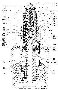
Figs. 1 to 3 show a first embodiment of a discharge apparatus of a
dispenser according to the invention, in which the medium reservoir
belonging to the dispenser is not represented. The figures show
various stages during an actuating operation for the conveyance of
a medium present in the medium reservoir.
The discharge apparatus essentially has four subassemblies 12, 14,
16, 18, which are configured such that they are axially mutually dis-
placeable along a principal axis 10. The subassemblies in question
are an applicator subassembly 12, a finger rest subassembly 14, a
discharge valve subassembly 16 and a piston subassembly 18.
The finger rest subassembly 14 is configured such that it is axially
displaceable relative to the applicator subassembly 12 between a
first, upper actuating end position and a second, lower actuating end
position. The discharge valve subassembly 16 is configured such
that it is axially displaceable relative to the applicator subassembly
12 between an upper closing position and a lower opening position.
CA 02537011 2006-02-20
14
The piston subassembly 18 is configured such that it is axially
displaceable relative to the applicator subassembly 12 between a
first, upper stroke end position and a second, lower stroke end posi-
tion. The applicator subassembly 12 itself is fixedly connected to the
medium reservoir (not represented in the figures).
The applicator subassembly 12 consists of a substantially cylindrical
nose applicator 22 having a discharge opening 22a disposed at the
upper end, a screw fastening 24, by which the nose applicator 22 is
connected to a medium reservoir (not represented), a medium sup-
ply apparatus 26, disposed within the screw fastening 24 and the
nose applicator 22 and comprising an axially aligned medium duct
26b, as well as a blocking insert 28 disposed in the medium duct
26b and an inlet valve piece 30a likewise disposed in the medium
duct 26 over the blocking insert 28. Above the inlet valve piece 30a
there is provided in the medium supply apparatus a radial through
bore 26e, through which medium fed through the medium duct 26
can make its way into a dosing chamber 54. Above and below the
blocking insert 28, radial through bores 26c, 26d are provided in the
medium supply, which allow the blocking insert 28 to be by-passed
in the course of the conveyance of the medium. Disposed in the
through bore 26e is a ball valve 30b, which, together with the inlet
valve piece 30a, forms a ball seat valve 30, which opens when an
underpressure obtains in the dosing chamber 54.
The components 22, 24, 26, 28, 30 of the applicator subassembly
12 are fixedly connected to one another and are configured such
that their relative position does not alter if the dispenser is used ac-
cording to specification.
The second subassembly, the finger rest subassembly 14, consists
merely of the finger rest 32. The finger rest 32 has a cylindrical sec-
tion, having a cylindrical wall 32a, and an actuating section 32b, ex-
tending radially therefrom, for the resting of the fingers. The cylindri-
CA 02537011 2006-02-20
cal section is of double-walled construction in an upper region
and has an inner wall 32d. The lower end of the cylindrical wall 32a
constitutes a functional section 32c, the working of which will be fur-
ther described later. The finger rest 32 is slipped onto the applicator
5 subassembly 12 from outside and is axially movable relative to the
latter between a first actuating end position, represented in Fig. 1,
and a second actuating end position, represented in Fig. 3.
The third subassembly, the discharge valve subassembly 16, has a
10 one-piece valve element 34 having a cylindrical main section 34e. At
the lower end of the main section 34e there is provided an actuating
ring 34a. At the upper end of the main section 34e, an upwardly
closed inner cylinder 34c is integrated, via radial webs 34b, inte-
grally into the valve element 34. At the upper end of this inner cylin-
15 der 34c, a closing pin 34d, extending axially upward, is molded onto
the inner cylinder 34c. The valve element 34 is axially displaceable
relative to the applicator subassembly 12. The upper end position of
the valve element 34, represented in Figs. 1 and 2, constitutes a
closing state, in which the closing pin 34d, in the region of the dis-
charge opening 22a of the nose applicator 22, bears flush against
an annular surface 22b of the nose applicator 22 and thereby pre-
vents a medium discharge through the discharge opening 22a. The
lower end position of the valve element 34 relative to the applicator
subassembly 12, represented in Fig. 3, constitutes the opening state
in which the annular surface 22b of the nose applicator 22 and the
closing pin 34d are spaced apart in the direction of the principal axis
10, enabling pressurized medium to escape through the discharge
opening 22a.
The last subassembly, the piston subassembly 18, consists of a to-
tal of three components. These components are a carrier 36, a seal-
ing ring 38 and a piston packing 40. These components 36, 38, 40
are fixedly connected to one another and do not alter their relative
position if the dispenser is used according to specification. The car-
CA 02537011 2006-02-20
16
rier 36 has a cylindrical section 36a, adjoined at the lower end
by an outward-pointing radial section 36b. Molded onto this radial
section 36b are latch bosses 36c, which extend outward away from
the principal axis 10. The latch bosses 36c are of elastic configura-
tion and are formed such that they can be deflected radially inward.
In the region of the transition between the cylindrical section 36a
and the radial section 36b of the carrier 36, the latter is fixedly con-
nected to the inner sealing ring 38. The upper end of the carrier 36
is adjoined by the piston packing 40, which consists of an elastic
material. The piston packing 40 has a substantially cylindrical basic
form, exhibiting the greatest external diameter at its upper end 40a
and the smallest internal diameter at its lower end 40b. It is con-
nected to the carrier 36 in such a way that its lower end 40b is dis-
posed inside the cylindrical section 36a and its upper end projects
upward over the carrier 36. The piston subassembly 18 is disposed
within the nose applicator 22 and the discharge valve subassembly
16 is disposed in the discharge apparatus and encloses the medium
supply apparatus 26. The sealing ring 38 and the lower end 40b of
the piston packing 40 are configured such that they form a tight in-
ward seal against the medium supply apparatus. The upper end 40a
of the piston packing 40 is configured such that it forms a tight out-
ward seal against the inner side of the main section 34e of the valve
element 34. The piston subassembly 18 is configured such that it is
displaceable between a first, upper stroke end position and a sec-
ond, lower stroke end position, the first, upper stroke end position
being determined by a stop position of the piston packing 40 at the
end of the cylindrical section 34e of the valve element 34 and the
lower stroke end position being defined by a decoupling web 24b of
the screw fastening 24 of the applicator subassembly 12, against
which the latch bosses 36c are forced radially inward out of the op-
erative connection with the functional section 32c of the finger rest
32, thereby preventing any further movement of the piston subas-
sembly 18 in the downward direction. This is explained in greater
detail further below.
CA 02537011 2006-02-20
17
The discharge apparatus represented in Figures 1 to 3 has a total of
three springs, by which the finger rest 32, the valve element 34 and
the piston subassembly 18, relative to the applicator subassembly
12, are subjected to force in the direction of their respectively upper
end position. The finger rest 32 is forced upward by the finger rest
spring 46, which is supported on an annular shoulder 22c of the
nose applicator 22. The valve element 34 is forced into its closing
position by a valve spring 48, the valve spring 48 being held in a
downwardly closed-off cylindrical supporting section 26a at the up-
per end of the medium supply apparatus 26, and in the inner cylin-
der 34c of the valve element 34. The piston subassembly 18 is
acted upon by an energy store spring 50 in the direction of its first,
upper stroke end position.
The described discharge apparatus represented in Figs. 1 to 3 func-
tions as a user-independent discharge apparatus. This means that
the dosing quantities and the discharge pressure are independent of
the manner of the actuation by the operator.
The working method of the described dispenser is set to be illus-
trated with reference to the sequence of Figs. 1 to 3:
Fig. 1 shows the dispenser in a starting position. The finger rest 32,
the valve element 34 and the piston subassembly 18 are found re-
spectively - acted upon by the respective springs 46, 48, 50 - in
their upper end position. In this upper end position, the functional
section 32c of the finger rest 32 is disposed above the latch bosses
36c of the carrier 36 of the piston subassembly 18. The latch bosses
36c are in a non-deflected state and extend through axially aligned
cutouts 22d in the nose applicator 22 to below the functional sec-
tions 32c of the finger rest 32. The dosing chamber 54 located be-
tween the piston packing 40 and the dosing element 34 has, in this
stage, a minimum volume.
CA 02537011 2006-02-20
18
Starting off from this state, the finger rest 32 is pressed downward
by an operator relative to the applicator subassembly 12 and
counter to the spring force of the finger rest spring 46. Since the
latch bosses 36c are disposed beneath the functional sections 32c,
the piston subassembly 18, too, is likewise forced downward jointly
with the finger rest 32. This produces a volume enlargement of the
dosing chamber 54. The underpressure which is thereby formed
opens the ball seat valve 30 and draws medium into the dosing
chamber 54. This medium, starting from the medium reservoir (not
represented in the figures), hereupon takes a path through the me-
dium duct 26b of the medium supply apparatus 26, through the
lower through bores 26c beneath the blocking insert 28 out of the
medium supply apparatus 26, and through the upper through bores
26d above the blocking insert 28 back into the medium supply appa-
ratus 26. With progressive displacement of the finger rest 32 in the
downward direction and the parallel displacement of the piston sub-
assembly 18 in the downward direction, the dosing chamber 54, ac-
cordingly, is increasingly filled. Meanwhile, the energy store spring
50, which subjects the piston subassembly 18 to an upwardly di-
rected force, is increasingly compressed and, hence, tensioned. An
unwanted escape of the medium oufirvard in the section between the
first through bores 26c and the second through bores 26d is pre-
vented by the sealing ring 38 and the lower end 40b of the piston
packing 40, which tightly seal, at the bottom and top respectively, an
annular through chamber, which is closed off on the inside by the
medium supply apparatus and on the outside by the valve element.
An escape of the medium through the discharge opening is not pos-
sible during this phase of the actuation, since the closing pin 34d
bears flush against the annular surface 22b of the nose applicator
22 and thus seals the discharge opening 22a.
Fig. 2 shows a state of the dispenser in the first embodiment shortly
before the start of the discharge operation. The finger rest 32 is here
CA 02537011 2006-02-20
19
pressed so far downward that the lower end 40b of the piston
packing 40 covers the upper through bores 26d and thus prevents a
further influx of medium into the dosing chamber 54. The piston
subassembly 18 is displaced, together with the finger rest 32, suffi-
ciently far down that the latch bosses 36c have made their way into
that region of the cylindrical decoupling web 24b which is molded
onto the screw fastening 24 and, as the finger rest 32 and the piston
subassembly 18 are progressively pressed down, are deflected ra-
dially inward by the said decoupling web. The contact surface be-
tween the functional section 32c of the finger rest 32 and the latch
bosses 36c of the carrier 36, commencing with the time of initial
contact between the latch bosses 36c and the decoupling web 24b,
therefore becomes increasingly small.
The result is that, as the finger rest 32 is progressively pressed
down, the functional section 32c loses contact with the latch bosses
36c and these spring onto the inner surface of the cylindrical wall
32a of the finger rest 32. From this moment, the piston subassembly
18 can be forced upward without hindrance from the energy store
spring 50. The latch bosses 36c hereupon slide upward along with
it, on the inner side of the cylindrical wall 32a of the finger rest 32.
As a result of the action by the spring force of the energy store
spring 50, the medium in the dosing chamber 54 is pressurized, an
escape of the medium back into the medium reservoir being pre-
vented by the ball seat valve 30.
The movement of the finger rest 32 up to an actuating end position,
in which the functional section 32c of the finger rest 32 rests upon
the decoupling web 24b of the screw fastening 24, has the effect,
apart from the decoupling of the latch bosses 36c from the func-
tional sections 32c, that the downward-pointing front face of the cy-
lindrical inner wall 32d of the finger rest 32 forces the actuating ring
34a of the valve element 34, and hence the entire valve element 34,
downward. Consequently, the closing pin 34d is lifted off downward
CA 02537011 2006-02-20
from the annular surface 22b of the nose applicator 22 and the
discharge opening 22a for the medium present in the dosing cham-
ber 54 is thereby made accessible.
5 Fig. 3 shows a state toward the end of the medium discharge. The
medium present in the dosing chamber 54 is forced out of the dis-
charge opening 22a by the pressure generated by the energy store
spring 50 and thus escapes in a precisely defined quantity. The dis-
charge operation ends when the piston packing 40 butts against the
10 end of the cylindrical section 34e of the valve element 34 and the
dosing chamber 54 can consequently be diminished no further.
Once the discharge operation is concluded, the finger rest 32 is
guided back upward and released by the operator and is conse-
quently forced upward by the tensioned spring rest spring 46. Once
15 the finger rest 32 has reached the upper actuating end position, the
functional section 32c is located, once again, above the latch
bosses 36c of the carrier 36 of the piston subassembly 18. The latch
bosses 36c are therefore forced outward back into a non-deflected
position and thus reengage with the finger rest 32. The starting state
20 for a further actuation is thus achieved.
It should particularly be emphasized with this first embodiment that
the medium quantity in the dosing chamber 54 is not determined by
the lower stroke end position, in which the latch bosses 36c disen-
gage from the functional sections 32c of the finger rest 32, but is in-
stead defined by the setting from which the lower ends 40b of the
piston packing 40b seal off the upper through bores 26d of the me-
dium feed 26. A particularly high dosing accuracy is thereby
achieved, since the dosing accuracy is not dependent on the posi-
tion in which the latch bosses 36c disengage from the functional
sections 32c, which position varies to a certain extent. The second
peculiarity of this embodiment lies in the fact that the discharge
valve formed by the closing pin 34d and the annular surface 22b of
the nose applicator 22 is not opened on a pressure-dependent ba-
CA 02537011 2006-02-20
21
sis. Instead, an opening of the discharge valve is compelled by
the fact that the actuating ring 34a of the valve element 34 is forced
downward directly by the finger rest 32. The advantage with this so-
lution is that the discharge valve does not need to be specially
adapted for dispensers of different type anal of different maximum
pressure in the dosing chamber.
Fig. 4 shows a second embodiment of a discharge apparatus of a
dispenser according to the invention.
Just like the first embodiment represented in Figs. 1 to 3, this sec-
and embodiment has four mutually displaceable subassemblies, an
applicator subassembly 112 having a nose applicator 122, a finger
rest subassembly 114, a discharge valve subassembly 116 and a
piston subassembly 118 having a valve element 134. With respect
to the interaction of the finger rest subassembly 114 and the piston
subassembly 118 in the coupling and decoupling of the subassem-
blies, the working method of this second embodiment is consistent
with the working method of the embodiment of Figs. 1 to 3: When a
finger rest 132 is pressed down, a cylindrical guide section 133, fix-
edly connected to the finger rest 132 and having a functional section
133c, is forced jointly downward. This functional section 133c forces
downward the piston subassembly 118, which is operatively con-
nected by a latch boss 136c to the finger rest subassembly 114.
Upon this - similarly to the first embodiment - an energy store
spring 150 is compressed. Once a cylindrical decoupling web 122b
is reached by the latch boss 136c in the course of the finger rest
subassembly 114 being pressed down, the latch boss 136c is forced
radially inward and thus enters a state decoupled from the functional
section 133c. The piston subassembly 118 can then be forced up-
ward by the energy store spring 150, whereupon the volume of a
dosing chamber 154 is reduced and the medium present therein is
pressurized.
CA 02537011 2006-02-20
22
This represented second embodiment differs from the first
embodiment of Figs. 1 to 3 particularly in respect of two aspects:
On the one hand, the displacement of the valve element 134 with
the closing pin 134d is pressure-dependent and the discharge valve
is therefore pressure-activated, so that the discharge automatically
takes place once a necessary limit pressure is reached in the dosing
chamber. On the other hand, the actuating operation differs in terms
of the process of filling the dosing chamber 154 with the medium.
While the first embodiment of Figs. 1 to 3 envisages that the dosing
chamber 54, as a result of the generated underpressure, is immedi-
ately filled in the course of the actuation, in this second embodiment
it is envisaged that, as a result of the actuation, a pronounced un-
derpressure or a vacuum is generated in the dosing chamber 154,
which is subsequently used, in the course of the actuation, to suck
in the medium. For this purpose, a medium supply device 126, in
this second embodiment, is designed such that, in the starting posi-
tion represented in Fig 4, no connection exists between the dosing
chamber 154 and a medium duct 126b. This is achieved by a con-
figuration of a piston packing 140 belonging to the piston subas-
sembly, which piston packing, in this starting position, bears with an
inward-pointing sealing web 140d, which limits the dosing chamber
154 in.the downward direction, flush against a sealing cylinder 126f
adjoining the medium supply device at the top. In the course of the
finger rest 132 being pressed down and of the piston packing 140
being displaced to the same extent, the dosing chamber 154 is
enlarged with respect to its volume, the sealing web 140d terminat-
ing, over a first part-section of the movement, with the sealing cylin-
der 126f. Only once the piston packing 140 or the sealing web 140d
of the piston packing 140 makes its way into the region of a through
bore 126e of the medium supply apparatus 126 is a direct and unin-
terrupted connection established between the medium reservoir and
the dosing chamber 154. Due to the underpressure developed in the
CA 02537011 2006-02-20
23
dosing chamber 154, the medium flows at this moment out
of the medium reservoir through the medium duct 126b into the dos-
ing chamber 154. After the latch boss 136c is forced inward against
the decoupling web 122b and is freed from engagement with the
functional section 132c, as the finger rest 132 continues to be
pressed down, the piston subassembly 118, and hence the piston
packing 140, darts upward under the action of the energy store
spring 150. At the moment in which the sealing section 140d comes
back into the region of the sealing cylinder 126f, the dosing chamber
154 is separated from the medium reservoir. From this moment, the
pressure in the dosing chamber 154 is increased as a result of the
reduction in volume and the force subjected upon the cylinder sub-
assembly. As soon as the pressure in the dosing chamber has ex-
ceeded a discharge limit value, the valve element 134, and the clos-
ing pin 134d molded thereto, is forced downward counter to the
spring force of a valve spring 148, and the discharge operation
commences through a discharge opening 122a. The discharge op-
eration is continued until such time as the .dosing chamber 154 is
completely reduced in size and the pressure in the dosing chamber
154 has fallen below this limit value and the closing pin 134d of the
valve element 134 seals off the discharge opening again.
The peculiarity of this second embodiment lies in the manner in
which the medium is conveyed into the dosing chamber. Differently
than in the first embodiment, in which the conveyance commences
simultaneously with the displacement of the piston packing 40, in
this second embodiment a vacuum or a pronounced underpressure
is firstly developed in the dosing chamber 154, which, in the further
course of the actuation, leads to the conveyance of a defined quan
tity of the medium.
Fig. 5 shows a third embodiment of a discharge apparatus of a dis-
penser according to the invention. This - just like the first two em-
bodiments - has four mutually separate subassemblies. An applica-
CA 02537011 2006-02-20
24
for subassembly 212 having a nose applicator 222 is in this
case fixedly connected, in a non-represented manner, to a medium
reservoir. A finger rest subassembly 214 is arranged such that it is
axially displaceable in the direction of a principal axis 210 relative to
the applicator subassembly 212. Within the applicator subassembly
212, a discharge valve subassembly 216 and a piston subassembly
218 are arranged such that they are axially displaceable relative to
the applicator subassembly 212.
The finger rest subassembly comprises a finger rest 232 and a cy-
lindrical guide section 233 having an inward-jutting functional sec-
tion 233c. The piston subassembly 218 consists of a carrier 236 and
a piston packing 240. The carrier 236 has, at the lower end, latch
bosses 236c, which, in a non-deflected state, as represented in Fig.
5, are extended radially outward into the region of the functional
section 233c. Above the piston packing 240 there is disposed a dos-
ing chamber 254, which is closed off in the upward direction by a
wall insert 260 belonging to the applicator subassembly 212.
Through a through duct 240e in the piston packing 240, the dosing
chamber 254 is connected by a medium duct 226b to the medium
reservoir (not represented in Fig. 5). Above the through duct 240e, a
ball seat valve 240f is provided, which is configured such that it
closes when a pressure higher than that in the medium reservoir
obtains in the dosing chamber 254. The wall insert 260 which closes
off the dosing chamber 254 in the upward direction separates the
dosing chamber 254 from a pressure chamber 262. Medium can
make its way out of the dosing chamber 254, via a second ball seat
valve 260a, into this pressure chamber 262. The second ball seat
valve 260a is here configured such that it opens when the pressure
in the dosing chamber 254 is greater than the pressure in the pres-
sure chamber 262. When the pressure in the pressure chamber 262
has exceeded a discharge limit pressure, a valve element 234 of the
discharge valve subassembly 216 is displaced in the axially down-
ward direction axially counter to an upward-acting spring force of a
CA 02537011 2006-02-20
valve spring 248, thereby enabling the medium to be
sprayed through the discharge opening 222a.
The working method of this embodiment, as far as the generation of
5 the pressure in the dosing chamber 254 is concerned, is broadly
comparable with the first embodiment represented in Figs. 1 to 3.
The finger rest 232, once again, is pressed manually downward,
whereupon the piston subassembly 218, because of the coupling of
the latch bosses 236c to the functional sections 233c, is likewise
10 forced downward. As in the illustrative embodiment of Figs. 1 to 3,
medium hence flows into the dosing chamber 254, since the ball
seat valve 240f opens due to the underpressure obtaining in the
dosing chamber 254 as a result of the volume enlargement. Unlike
the second described embodiment, the discharge valve is not, how-
15 ever, opened in dependence on the pressure obtaining in the dosing
chamber 254, but instead in dependence on a pressure obtaining in
the pressure chamber 262. When, following the decoupling of the
latch bosses 236c from the functional sections 233c by means of
decoupling sections 224b, a volume diminution of the dosing cham-
20 ber and an accompanying pressure increase within the dosing
chamber 254 takes place, medium is conveyed from the dosing
chamber 254 into the pressure chamber 262. Insofar as the pres-
sure which is thereby created in the pressure chamber 262 is not yet
sufficient to open the discharge valve, the medium present in the
25 pressure chamber 262 remains in the pressure chamber 262 until a
subsequent next actuation of the dispenser, since the valve 260a
prevents the medium from flowing back into the dosing chamber 254
or into the medium reservoir. As long as the discharge valve does
not open, the pressure within the pressure chamber 262 can conse-
quently only keep on rising upon subsequent actuations of the dis-
charge apparatus. Once the pressure in the pressure chamber 262
is high enough, each further actuation of the dispenser and each
further quantity of the medium supplied via the dosing chamber 254
leads always to a discharge process. When the dispenser compris-
CA 02537011 2006-02-20
26
ing such a discharge apparatus is first used, it has therefore to
be actuated a few times until the pressure in the pressure chamber
262 is sufficient to effect a discharge operation.
The advantage with the represented embodiment is that, as a result
of the separation of pressure chamber 262 and dosing chamber
254, the volume of the dosing chamber 254 in the non-actuated
state is relatively small. The result of this is that the pressure in the
dosing chamber rises very strongly in the course of the actuation.
The pressure in the pressure chamber 262 increases incrementally
with each actuation of the discharge apparatus, until such time as
the limit pressure necessary to open the discharge valve is reached.
In this way, very high discharge pressures and corresponding dis-
charge characteristics of the dispenser are able to be attained.
Due to its construction with two valves 240f, 260a, the discharge
apparatus represented in Fig. 5 can therefore be superior to a dis-
charge apparatus in which the pressure chamber and the dosing
chamber are configured as a unitary and not a valve-interrupted
chamber. In such a discharge apparatus, it has to be feared, in case
of poor design, that the, in the course of actuation, increased pres-
sure in a unitary dosing and pressure chamber results merely in a
compression of the residual air present in the unitary dosing and
pressure chamber, the pressure not being sufficient, however, to
open the discharge valve. Upon the next actuation, this compressed
air would be further decompressed and then recompressed, without
any change in pressure ratios in the unitary dosing and pressure
chamber compared with the previous actuation. Since the air cannot
escape, however, it would not be possible to actually start using the
dispenser.
Figs. 6a and 6b and Figs. 7a and 7b show a further embodiment of
a dispenser according to the invention. The fundamental construc-
tion of this fourth embodiment of a dispenser according to the inven-
CA 02537011 2006-02-20
27
tion is consistent with the construction of the dispensers
represented in Figs. 1 to 5, inasmuch as four mutually separated
and axially mutually displaceable subassemblies are likewise pro-
vided, constituted by an applicator subassembly 312 fixedly con-
s nected to a medium reservoir and comprising a nose applicator 322,
a finger rest subassembly 314, a discharge valve subassembly 316
and a piston subassembly 318. The interaction of the finger rest
subassembly 314, the applicator subassembly 312 and the piston
subassembly 318, and the manner of the conveyance of the me-
dium from the medium reservoir into a dosing chamber 354, here
broadly corresponds to the second embodiment represented in Fig.
4. The basic difference to this and all other above-described em-
bodiments lies in the nature of the coupling and decoupling of the
finger rest subassembly 314 to/from the piston subassembly 318 in
the course of the actuation of the dispenser, and in the motional se-
quence of the piston subassembly 318 following the decoupling from
the finger rest subassembly 314 in the second, lower stroke end po-
sition.
Figures 6a and 6b, on the one hand, and Figures 7a and 7b, on the
other hand, respectively show a state of the discharge apparatus,
once in a sectioned side view and once in a likewise sectioned view
from diagonally above.
In the represented embodiment, the finger rest subassembly 314
comprising a finger rest 332, the applicator subassembly 312 and
the piston subassembly 318 are configured such that the movement
of the piston subassembly 318 from a second, lower stroke end po-
sition into a first, upper stroke end position is realized in the form of
a translatory motion in the direction of a principal axis 310, with si-
multaneous rotary motion about the principal axis 310. While the
finger rest subassembly 314 is connected to the applicator subas-
sembly 312 in a rotationally secure manner, so that the finger rest
subassembly 312, relative to the applicator subassembly, has only a
CA 02537011 2006-02-20
28
translatory degree of freedom in the axial direction, the piston
subassembly 318 is guided with restricted rotatability on a cylindrical
outer surface of a medium supply apparatus 326.
The concrete configuration and the advantages of the coupling and
decoupling apparatus of the embodiment represented in Figs. 6a to
7b are described below.
The applicator subassembly 312 has a cylindrically configured guide
section 324c, which is molded onto a screw fastening 324 and the
inner side of which is provided with a sawtooth profiling 366. The
sawtooth profiling 366 consists of individual sawteeth 368, which,
respectively, are mutually separated by grooves 370 extending in
the direction of the principal axis 310. The sawteeth 368 respectively
have a vertical flank 368a, extending in the direction of the principal
axis 310, and a screw-section-shaped control cam flank 368b, con-
figured as a control cam and lying opposite the vertical flank 368a.
The sawteeth are respectively identically aligned, so that the control
cam flanks 368b, if the control cylindrical section is viewed in the
direction of the principal axis 310, are either all in clockwise align-
ment or all in counterclockwise alignment.
The piston subassembly 318 has a piston packing 340 and a carrier
336. Molded onto the carrier 336 are a total of six vanes 372 extend-
ing radially outward, which are spaced 60° apart and have a radial
length which makes them jut into the grooves 370. The vanes 372
have a rectangular cross-sectional area, two parallel, mutually op-
posing support surfaces 372a, corresponding with the grooves 370
in the sawtooth profiling 366, being realized perpendicularly and
parallel to the principal axis 310. A third, diagonally upward pointing
contact surface 372b is inclined by an angle of about 60° relative to
the principal axis 310, the alignment of this contact surface 372b
corresponding with the opposite control cam flanks 368b of the saw-
teeth 368.
CA 02537011 2006-02-20
29
The finger rest 332 has a total of twelve circularly arranged pusher
arms 332e, respectively spaced 30° apart, which respectively ex-
tend identically from the principal axis 310, at a distance apart in the
direction of the principal axis 310, from above into the guide cylinder
section 324c of the applicator subassembly 312. At their end, the
pusher arms 332e respectively have a contact surface 332f, which is
tilted relative to the principal axis 310 to the same degree as the
contact surfaces 372b of the vanes 372 of the carrier 336. Their di-
rection of tilt herein corresponds to the direction of tilt of the control
cam flanks 368b of the sawteeth 368.
As already explained above, the finger rest 332 and the applicator
subassembly 312 are mutually connected in a rotationally secure
manner. For this purpose, on the screw fastening 324 belonging to
the applicator subassembly 312, a groove 324d is provided, in which
a securing section 332g of the finger rest 332 engages. The rota-
tional position of the finger rest relative to the guide section 324c is
defined such that each pusher arm 332e is assigned a groove 370
and lies opposite this groove.
The carrier 336 is represented in Figs. 6a and 6b in its first, upper
stroke end position. The six vanes 372 of the carrier 336 extend ra-
dially outward into the grooves 370 in the sawtooth profiling 366.
Since the vanes 372 are spaced respectively 60° apart and the
grooves 370 are spaced respectively 30° apart, a vane 372 of the
carrier 336 is present in only every second groove 370 in each case.
The finger rest 332 is in its upper actuating end position. In this up-
per actuating end position, the pusher arms 332e extend downward
into the guide cylinder section 324c and there bear with their contact
surfaces 332f flush against the contact surfaces 372b of the vanes
372 of the carrier 336.
CA 02537011 2006-02-20
Starting from this starting position, a depression of the
finger rest 332 results in the carrier 336, too, being forced down-
ward, since six of the contact surfaces 332f of the pusher arms 332e
press upon the contact surfaces 372b of the vanes 372 of the carrier
5 336. Apart from the force which hence acts upon the carrier 336,
downward in the direction of the principal axis 310, the force applied
via the finger rest 332 and the pusher arms 332e also causes a
torque to be generated, since the carrier 336, in accordance with the
alignment of the contact surfaces 372b, 332f and due to its subjec-
10 tion to an upwardly directed spring force by an energy store spring
350, attempts to slide off from pusher arms 332d. This sliding-off is
prevented, however, by the vertical tooth flanks 368a of the saw-
teeth 368 of the sawtooth profile 366. Through the depression of the
finger rest 332, the piston subassembly 318 is therefore forced
15 down to the same extent, without any possible change in the rota-
tional position of the piston subassembly 318.
During the depression of the finger rest and of the piston subas-
sembly 318, an underpressure or vacuum comes to be generated in
20 the dosing chamber 354, in the same manner as described in rela-
tion to the second embodiment, represented in Fig. 4, whereafter
medium, after having reached a through bore 326b through a seal-
ing web 340d which closes off the dosing chamber 354 in the
downward direction, proceeds to flow into the dosing chamber 354.
If the finger rest 332, jointly with the piston subassembly 318, is
pressed downward to the point where the upward-pointing edges
372c of the vanes 372 of the carrier 336 level with the downward-
pointing tips 368c of the sawteeth 368 are reached, the anti-twisting
protection for the carrier 336 is no longer present. In a spiral motion,
the vanes 372 of the carriers 336 then slide out of engagement with
the pusher arms 332e and onto the control cams 372b of the saw-
teeth 368. On the control cams 372b, the vanes 372 of the carrier
336, upon simultaneous rotation of the carrier 336, then slide on as
CA 02537011 2006-02-20
31
far as the setting represented in Figs. 7a and 7b. This produces a
diminution of the volume of the dosing chamber 354 and a pressure
increase in the medium present therein, so that, in the same manner
as in the other embodiments, a discharge operation is initiated. If the
finger rest 332 is then returned to its upper actuating-end position,
the vanes 372 slip back into their starting position in the grooves
370.
Compared with the first to third embodiments, this fourth embodi-
ment has two basic advantages: The represented motional se-
quence of the carrier 336, and hence of the piston packing 340,
leads to a retarded intake stroke in the course of the return stroke
motion, by which it is ensured that the filling of the dosing chamber
354 is concluded before the dosing chamber 354 is separated from
the medium reservoir by the sealing web 340d of the piston packing
340. This retarded motional sequence ensures that an underpres-
sure is not maintained in the dosing chamber 354 if, at the same
time, the target dosage is not reached. The second basic advantage
lies in the fact that - unlike in embodiments 1 to 3 - no elastic de-
formation of components is necessary for the coupling/decoupling of
the piston subassembly 318 to and from the finger rest 332. The risk
of failure of the discharge apparatus, through wear, or breakage of a
latch boss or some other elastic component, is thereby reduced.