Note: Descriptions are shown in the official language in which they were submitted.
CA 02537513 2011-12-16
28283-102
ADVANCED MICA BASED SEAL AND METHOD FOR MAKING AND USING
FIELD OF THE INVENTION
[0003] The present invention relates to an advanced multilayer compressive
seal, generally. More particularly, the present invention relates to an
advanced mica-
based sealing (gasket) member for use in multilayer compressive seals
applicable to
high-temperature devices and methods of making and using. High-temperature
devices include electrochemical devices such as solid oxide fuel cells, syngas
generators, and membrane reactors whereby different gaseous streams internal
to
the device at elevated temperatures must be kept separate from each other. The
sealing member and compressive seal of the present invention exhibit superior
thermal cycling stability and low effective leak rates compared to other seals
known in
the art.
1
CA 02537513 2006-03-02
WO 2005/024280 PCT/US2004/029062
BACKGROUND OF THE INVENTION
[0004] High-temperature devices that can convert chemical energy of a
fuel such as hydrogen directly into electrical energy at high efficiency and
low or
no air pollution are of great commercial interest. Such devices include high-
temperature electrochemical devices, solid oxide fuel cells (SOFC), and other
similar structures such as interconnects. Electrochemical devices having
multiple components, such as, for example, solid oxide fuel cell (SOFC)
stacks,
syngas membrane reactors, oxygen generators and the like require seals to
io separate the various gaseous components [e.g., H2 (fuels) and 02
(oxidants)]
and to prevent the streams from mixing with each other. Mixing of the gas
streams has a variety of negative consequences, depending upon the type of
device and the composition of the gaseous streams. One major problem
resulting from mixing of such gases is the possibility of thermal combustion
of the
gases and the resulting failure of the device. Thus, to ensure high efficiency
and
to maintain the stack structural integrity, seals are needed to separate the
various gaseous components (fuels and oxidants). Such seals must be non-
conducting, have chemical, mechanical, and/or thermal compatibility with other
structural components of the devices. The seals must also exhibit very low
operational leak rates in severe (oxidizing, reducing, and humid) environments
as well as long-term thermal cycling stability at elevated temperatures.
[0005] Continued thermal cycling at high operating temperatures up to
about 850 C results in increased leak rates in mica-based compressive seals,
a
consequence of damage resulting from fragmentation, cleavage, micro-stress
fractures, and similar processes to the microstructure of the mica substrate
-2-
CA 02537513 2006-03-02
WO 2005/024280 PCT/US2004/029062
matrix. Such damage introduces leak paths or void spaces (interstices) that
are
continuous in three dimensions. High leak rates and thermal cycling
instability of
current seals under routine high temperature operation represent two of the
most
challenging hurdles remaining for significant advancement to be made in the
long-term success of high-temperature devices, including electrochemical
devices such as SOFCs, and/or toward developing and/or deploying long-term
viable components in other similar high temperature devices.
[0006] Accordingly, there remains a need to provide advanced seals and
sealing structures having low effective leak rates and superior thermal
cycling
io stability such that at the operating temperatures of these high temperature
devices (up to about 850 C), gaseous leaks (e.g., H2 gas into the air stream
or
vice versa) do not cause undesirable local heating leading to structural or
functional failure of the device.
SUMMARY OF THE INVENTION
[0007] The present invention relates generally to components, structures,
and methods for preparing seals applicable for sealing in high-temperature
devices. More particularly, the present invention is an advanced mica-based
sealing (gasket) member that finds application in multilayer compressive seals
useful in high-temperature devices such as electrochemical cells, solid oxide
fuel
cells, gas reactors, syngas reactors, and the like. The sealing member of the
present invention exhibits superior thermal cycling stability and effectively
low
leak rates at high operating temperatures up to about 850 C, and methods for
making and using the same.
-3-
CA 02537513 2006-03-02
WO 2005/024280 PCT/US2004/029062
[0008] In a previous invention (U.S. application, Serial Number 10/134,072
filed April 27, 2002) we have demonstrated that by adding additional compliant
interlayers (glass or metal) to mica-based seals, leak rates at about 800 C
can
be reduced several thousand times compared to mica-based seals presently
known in the art. A barium aluminum silicate glass (G-18) is one of a number
of
representative materials found to exhibit excellent Coefficient of Thermal
Expansion (CTE) matching properties for use in SOFC and electrochemical
devices, as detailed in U.S. patents to Meinhardt et al. (US6430966 and
US6532769) hereby incorporated by reference.
[0009] The multilayer compressive seal of the instant invention comprises
a sealing (gasket) member having a mica based member infiltrated with at least
one member selected from of a group of a suitable glass forming, melt forming,
or composite material(s), and, at a minimum, two (2) compliant glass or metal
interlayers disposed so as to be aligned with the opposing surfaces of the
sealing member. The sealing member may also be disposed so as to be in
contact with other materially and functionally important substrates, layers,
surfaces, junctions, interconnects, or components of the compressive seal or
of
the target application or device. For example, bounding surfaces of a typical
high-temperature device include such components as cathodes, anodes of an
electrochemical stack or device, YSZ components, interconnects, ceramics,
SOFC junctions and components, and the like. In one embodiment of the present
invention, the compliant glass or metal interlayers are disposed along the
opposing surfaces of an infiltrated sealing (gasket) member in further contact
with a bounding surface electrolyte or interconnect, thereby acting as an
interface between the sealing member and other non-compliant surfaces.
-4-
CA 02537513 2006-03-02
WO 2005/024280 PCT/US2004/029062
[0010] In a preferred embodiment, the sealing (gasket) member of the
present invention is composed of a mica in a paper form, e.g., as discrete
flakes
pressed into a thin paper. Phlogopite and Muscovite micas are available
commercially (McMaster-Carr, Atlanta, GA and Cogebi Inc., Dover, NH) in paper
form or as flakes. Other mineral types for mica include Biotite, Fuchsite,
Lepidolite, and Zinnwaldite, which may also find application.
[0011] For compressive seals, a degree of mismatch exists between the
various components of the compressive seal or device. To minimize the
mismatch, the sealing member of the present invention preferably comprises
io mica having a Coefficient of Thermal Expansion (CTE) in the range from 7-17
ppm/ C. Phlogopite, for example, has an average (room temperature to -800
C) CTE of about 10 ppm/ C; Muscovite has a comparable CTE of about 7
ppm/ C. Comparable metallic components (for example, interconnects for use in
SOFCs) have preferred CTE values in the range from about 12 ppm/ C to 17
ppm/ C. In addition, the selected micas are preferably of a paper form (i.e.,
as
discrete flakes pressed into a thin paper) thereby providing an open matrix
structure and for ease of handling. For example, Phlogopite mica papers are
easily infiltrated by delivering the infiltrating material (e.g., dissolved or
solvated
glass or melt forming material) in a carrier liquid to the top of the mica
paper. In
addition, they remain at a relatively constant thickness during handling. The
as
received naturally cleaved Muscovite mica, being in a monolithic form, has no
porosity but does cleave into multiple sublayers (-2-10 microns thick) after
firing
to a temperature >600 C as it loses chemical water (-4%) and tends to expand
significantly in apparent thickness as the sublayers become separated from
each
other. Since the naturally cleaved Muscovite mica as received has no cracks or
-5-
CA 02537513 2006-03-02
WO 2005/024280 PCT/US2004/029062
openings in the top sublayer, the infiltrating process requires soaking the
whole
mica sheet in the applicable infiltrating liquid or material. The sealing
(gasket)
member is preferably of a thickness in the range from about 25 microns to
about
1 millimeter. However, thickness of the mica is less important than that the
mica
be properly infiltrated and prepared for use as described hereinafter.
[0012] Prior to infiltration, the mica sealing member substrate may be
heated in an oven at a temperature between 500 C to 700 C for from I to 4
hours to remove any organic binders (typically present at about 3-4% by weight
in standard commercially available mica papers). Infiltration of the sealing
(gasket) member generally comprises introducing a glass or melt forming
material into the matrix of the mica substrate such that continuous flow paths
representing potential and real leak paths within the matrix are effectively
blocked and/or sealed. The infiltrating material comprises at least one member
of a suitable group of glass or melt forming materials, oxides, composites,
mica:glass composites, or like material(s). Upon heating, the infiltrating
material
becomes fixed in the plurality of spaces (voids, flow paths, leak paths,
necking
areas, interstitial spaces, gaseous leak paths, etc.) of the sealing member,
creating discontinuities in the three dimensional flow paths of the substrate
matrix, thereby effecting sealing. The infiltrated sealing member likewise
effects
sealing when incorporated in a multilayer compressive seal or selected high
temperature device.
[0013] In one embodiment of the method of the present invention,
infiltrating a sealing member for use as a sealing (gasket) member comprises
the
steps: 1) infiltrating (permeating) the sealing member matrix (mica substrate,
paper, etc.) with an infiltrating material, for example, a saturated liquid
solution
-6-
CA 02537513 2011-12-16
28283-102
comprising a dissolved or solvated glass (or melt) forming material, 2) fixing
(adhering) the glass forming material within the voids (and more specifically
at
junctions, necking areas, and/or interstitial spaces) of the matrix, for
example, by
drying the sealing member in an oven at a temperature of about 50 C for -1
hour, and 3) incorporating the infiltrated sealing member in a compressive
seal,
(e.g., in a hybrid multilayer seal under a selected compressive stress), or
assembling the sealing member as a component in a high-temperature device
for a desired application. For example, an infiltrated sealing member
incorporated in a compressive seal, electrochemical device, SOFC, or
io comparable device under compressive stresses in the range from 25 psi to
300
psi, more preferably in the range from 50 psi to 100 psi.
[0014] In yet another embodiment of the method of the present invention,
infiltrating the sealing member alternately comprises the steps: 1) providing
an
infiltrating material comprising mica (e.g., flakes or particles) and a glass
(or
melt) forming material in a mica:glass composite, 2) forming and/or fashioning
a
sealing (gasket) member in a desired shape and thickness using standard glass
forming, preparation, manufacturing, and/or processing techniques known to
those of ordinary skill in the art, e.g., slip-casting, tape casting, tape
calendaring,
die pressing, or the like), 3) fixing the infiltrated material within the
sealing
(gasket) member matrix at room temperature for - 4 hours or a temperature of
50 C for -1 hour, and 4) incorporating the infiltrated sealing member in a
compressive seal, or assembling in a high-temperature device.
7
CA 02537513 2011-12-16
28283-102
According to one aspect of the present invention, there is provided a
multilayer compressive seal for sealing in high temperature devices, the seal
comprising: a sealing member comprising a mica paper disposed between a first
and
a second compliant interlayer, said mica paper having a plurality of mica
members
therein infiltrated with at least one glass forming material that seals a
plurality of leak
paths between said plurality of mica members within said sealing member at an
operating temperature of said compressive seal, said sealing member provides a
sufficiently low effective leak rate in said compressive seal at said
operating
temperature.
According to another aspect of the present invention, there is provided
a multilayer compressive seal having superior thermal cycling stability for
sealing in
high temperature devices, the seal comprising: a sealing member comprising a
mica
paper disposed between a first and a second compliant interlayer, said mica
paper
having a plurality of mica members therein infiltrated with at least one glass
forming
material that seals a plurality of leak paths between said plurality of mica
members
within said sealing member at an operating temperature of said compressive
seal,
wherein said sealing member provides a sufficiently low effective leak rate in
said
compressive seal at said operating temperature.
According to still another aspect of the present invention, there is
provided a process for making a multilayer compressive seal having superior
thermal
cycling stability for sealing in high temperature devices, the process
comprising the
steps of: infiltrating a plurality of gas leak paths defined between a
plurality of mica
members disposed within a mica paper with an infiltrating liquid, the
infiltrating liquid
comprising at least one glass forming material therein; and affixing said at
least one
glass forming material at an operating temperature of said compressive seal to
seal
said plurality of gas leak paths within said sealing member whereby said
sealing
member provides a sufficiently low effective leak rate in said compressive
seal at said
operating temperature.
7a
CA 02537513 2011-12-16
28283-102
According to yet another aspect of the present invention, there is
provided a process for making a multi-layer compressive seal having superior
thermal
cycle stability for high-temperature electrochemical applications and
structures,
comprising: providing a sealing gasket member comprising an infiltration
material
wherein said member defines first and second generally flat opposing surfaces;
and
applying a compliant material to said first and second surfaces to form first
and
second compliant interlayers.
According to a further aspect of the present invention, there is provided
a process for making a multi-layer seal having superior thermal cycle
stability for
high-temperature electrochemical applications and structures, comprising:
providing
a sealing gasket member wherein said member defines first and second generally
flat
opposing surfaces; applying a compliant material to said first and second
surfaces to
form first and second compliant interlayers; and wherein said member is
infiltrated
with at least one glass or melt forming material.
According to yet a further aspect of the present invention, there is
provided a process for making a multi-layer compressive seal having superior
thermal
cycle stability for high-temperature electrochemical applications and
structures,
comprising: providing a glass infiltrated sealing gasket member defining first
and
second generally flat opposing surfaces; applying a compliant material to said
first
and second surfaces to form first and second compliant interlayers; and,
wherein said
seal is under a compressive stress.
According to still a further aspect of the present invention, there is
provided an electrochemical device, comprising: a plurality of components,
said
components forming at least one boundary between diverse gaseous streams and
defining at least one junction therebetween; a multi-layer compressive seal
positioned
at the junction, the seal composed of a sealing gasket member comprising an
infiltrating material said sealing member disposed between two compliant
interlayers,
wherein each compliant interlayer is disposed between the sealing member and
one
7b
CA 02537513 2011-12-16
28283-102
of said components; and a compression member for exerting a compressive force
to
the components and the sealing member.
According to another aspect of the present invention, there is provided
a solid oxide fuel cell assembly for electrochemically reacting a fuel gas
with a flowing
oxidant gas at an elevated temperature to produce a DC output voltage, said
solid
oxide fuel cell comprising: a plurality of generally planar integral fuel cell
units, each
unit comprising a layer of ceramic ion conducting electrolyte disposed between
a
conductive anode layer and a conductive cathode layer, wherein said units are
arranged one on another along a longitudinal axis perpendicular to said planar
units
to form a fuel cell stack; a multi-layer non-conducting seal disposed between
the
anode layer and the cathode layer of adjacent fuel cell units, wherein the
seal is
composed of an infiltrated sealing gasket member disposed between two
compliant
interlayers; and a compression member for exerting a compressive force along
the
longitudinal axis.
According to yet another aspect of the present invention, there is
provided a process for sealing a junction between adjacent ceramic or metallic
components of an electrochemical device, comprising: positioning between the
adjacent components a multi-layer seal comprising a sealing member infiltrated
with
at least one glass forming material wherein said member is disposed between a
first
compliant interlayer and a second compliant interlayer, wherein each of the
first and
second compliant interlayers is positioned between the sealing member and one
of
the components; and applying a compressive force to the components and the
seal.
According to still another aspect of the present invention, there is
provided a solid oxide fuel cell assembly for electrochemically reacting a
fuel gas with
a flowing oxidant gas at an elevated temperature to produce a DC output
voltage,
said solid oxide fuel cell comprising: a plurality of generally planar
integral fuel cell
units, each unit comprising a layer of ceramic ion conducting electrolyte
disposed
between a conductive anode layer and a conductive cathode layer, wherein said
units
7c
CA 02537513 2011-12-16
28283-102
are arranged one on another along a longitudinal axis perpendicular to said
planar
units to form a fuel cell stack; a multi-layer non-conducting seal disposed
between the
anode layer and the cathode layer of adjacent fuel cell units, wherein the
seal is
composed of a sealing member infiltrated with at least one glass forming
material or
composite disposed between two compliant interlayers; and a compression member
that exerts a selected compressive force along the longitudinal axis.
[0015] It will be recognized and appreciated by persons of ordinary skill in
the
art that infiltrating the mica-based matrix may be accomplished in a variety
of
7d
CA 02537513 2006-03-02
WO 2005/024280 PCT/US2004/029062
different ways. Thus, no limitation in scope is herein intended by the
disclosure
of the preferred embodiments.
BRIEF DESCRIPTION OF THE DRAWINGS
[0016] A more complete appreciation of the invention will be readily
obtained by reference to the following description of the accompanying
drawings
in which like numerals in different figures represent the same structures or
elements.
[0017] FIG. 1A. illustrates the microstructure in a commercially available
mica paper showing a continuous three-dimensional leak path following
"burnout" of the organic binder.
[0018] FIG. 1 B. shows a schematic drawing of a representative mica
paper infiltrated with a glass or melt forming material. The figure shows the
infiltrated mica paper at elevated temperature under applied stress with the
continuous leak path being blocked.
[0019] FIG. 1C. illustrates the differences in leak paths for the as-received
mica and the infiltrated mica paper (in a hybrid design with a compliant
interlayer
disposed adjacent on opposite sides of the mica paper). The leak path in the
as
received mica paper is continuous in three (3) dimensions.
-8-
CA 02537513 2006-03-02
WO 2005/024280 PCT/US2004/029062
[0020] FIG. 1 D. Schematic drawings illustrate the differences in leak
paths for the as-received mica and the infiltrated mica paper (in a hybrid
design
with a compliant interlayer disposed adjacent on opposite sides of the mica
paper). The leak path in the infiltrated mica paper is discontinuous and/or
limited
to two dimensions due to the sealed/filled and/or infiltrated interstitial
spaces and
necking areas.
[0021] FIG. 2 illustrates the effect of thermal cycling on normalized leak
rates for a non-infiltrated Phlogopite mica paper.
[0022] FIG. 3 illustrates shows the leak rates of two H3B03 (aq) infiltrated
Phlogopite mica papers (Samples A and B) versus the number of thermal cycles.
[0023] FIG. 4 illustrates the thermal cycling effect on normalized leak rates
at 800 C of the Bi(N03)3(aq)-infiltrated Phlogopite mica.
[0024] FIG. 5 shows leak rates results for a mica:glass (90 v%:10 v%)
composite seal compressed at 100 psi.
[0025] FIG. 6 shows the results of the mica:glass (80 v%:20 v%)
composite seal compressed at 50 psi.
DETAILED DESCRIPTION OF THE INVENTION
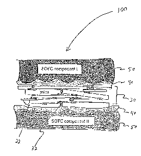
[0026] FIG. 1 illustrates the components of an advanced mica-based
sealing (gasket) member 30 and compressive seal 100 according to an
-9-
CA 02537513 2006-03-02
WO 2005/024280 PCT/US2004/029062
embodiment of the present invention. The sealing member 30 is generally
composed of a mica paper 20 comprising overlapping mica flakes 22
compressed in a thin paper form and a plurality of spaces (voids, flowpaths,
interstices, necking areas, leak paths, etc.) 24 (FIG. 1A). The microstructure
and
thermal behavior of mica papers have been described in some detail elsewhere
(see "Ultra-low Leak Rate of Hybrid Compressive Mica Seals for SOFCs",
Yeong-Shyung Chou, Jeffry W. Stevenson, and Lawrence A. Chick, Pacific
Northwest National Laboratories, Materials Resource Department, P.O. Box 999
Richland, WA 99352) hereby incorporated by reference. The sealing member 30
io is infiltrated as shown in FIG. 1 B whereby the voids and interstitial
spaces of the
mica paper 20 substrate or matrix are filled, sealed, or otherwise made
discontinuous with an infiltrating material 32. As shown in FIG. 1 C, the
infiltrated
sealing member 30 may then be incorporated as a central sealing component of
a compressive seal 100 or other high temperature device. The seal 100 further
comprises a 1 st and 2nd interlayer 40 of a compliant material, as for
example,
glass or metal (metal or metal foil), and a 1St and 2nd bounding component 50,
for
example a 1St and 2nd SOFC component (component I and component 11 in FIG.
1 C). The interlayers 40 may be of an identical or different material in the
seal
100 depending on the selection of bounding surface materials or components 50.
[0027] Two Phlogopite [(KMg3(AISi3O1o)(OH)2)] mica papers were tested,
Sample A [Phlogopite paper, McMaster-Carr, Atlanta, GA] having a nominal
thickness of about 100 microns (-4 mils), and Sample B [Cogemica AP-80,
Cogebi Inc., Dover, NH] having a thickness of about 75 microns (-3 mils).
Sample A contained an organic binder (between 2-5% by weight); Sample B
contained no organic binder. Examples I through 4 present different
-10-
CA 02537513 2006-03-02
WO 2005/024280 PCT/US2004/029062
embodiments of an infiltrated sealing (gasket) member 30 that may be
assembled in a compressive seal 100 or incorporated into a high-temperature
device.
-11-
CA 02537513 2006-03-02
WO 2005/024280 PCT/US2004/029062
EXAMPLE 1
[0028] In one embodiment, the infiltrated sealing (gasket) member 30 was
prepared using a liquid infiltration solution comprising at least one glass or
melt
forming material. The solid glass former was dissolved in an aqueous liquid to
a
point of saturation, and subsequently delivered into a plurality of spaces 24
(e.g.,
voids, interstices, flow paths, leak pathways, etc.) within the matrix of the
mica
substrate 20 using standard liquid delivery techniques (e.g., pipet).
Subsequent
drying of the substrate 20 fixes the glass or melt former within the matrix,
1o preparing the infiltrated sealing (gasket) member 30 for use. The sealing
member 30 was subsequently leak tested in a simulated multilayer compressive
seal (hybrid) 100 under a selected compressive stress in the range from 50 to
100 psi under repeated thermal cycling conditions and at expected operating
temperatures up to 850 C, and more preferably in the range from 650 C to
850 C.
[0029] Experimental. Sample A was heat treated at -700 C for 4 hours
to remove organic binders present in the substrate matrix prior to the liquid
infiltration step. Sample B was used as received. FIG. 1A illustrates the
typical
mica paper following removal of any organic binder (e.g., after "burnout").
The
figure shows a plurality of spaces (voids, continuities, flow paths,
interstitial
spaces) 24 of the mica substrate 20 member, prior to infiltration, comprising
three-dimensional flow paths largely responsible for generating gaseous leaks
in
a high-temperature device. FIG. 2 presents normalized leak rates as a function
of thermal cycles for a typical non-infiltrated Phlogopite mica (nominal
thickness
of about 0.1 mm), illustrating the effect of thermal cycling. As shown in the
figure,
-12-
CA 02537513 2006-03-02
WO 2005/024280 PCT/US2004/029062
thermal cycling under a compressive load of 100 psi leads to unacceptable leak
rates for the non-infiltrated mica paper, about 0.025 sccm/cm, on average.
[0030] Glass or melt forming materials suitable for infiltrating and
preventing leaks in the mica substrate are preferably a) non-corrosive, b)
soluble
in an aqueous medium, miscible in an organic solvent (e.g., Methyl Ethyl
Ketone), or mobile in a carrier liquid, and c) have melting point (MP)
temperatures above 450 C, more preferably in the range from about 450 C to
about 850 C so as to be operable in a high-temperature device. Solubility of
a
glass or melt forming material is a selection criterion based in part on
to convenience and ease of use. For example, boric acid (H3B03) has proven to
be
an excellent candidate based in part on its aqueous solubility, as well as its
melting point properties. Bismuth nitrate [Bi(N03)3.5H20] is equally workable
despite its more limited aqueous solubility due to its operable melting point.
Both
candidates are suitable infiltrating materials for effecting sealing in a
sealing
(gasket) member 30 destined for incorporation in a high temperature device. In
contrast, pure Si02, another oxide, is not an ideal material for infiltrating
the
sealing (gasket) member 30 given its many crystalline phases and exceptionally
high melting point (-1400 C). As another example, pure P205 is an equally
daunting material, given the corrosivity and reactivity in the reducing and
wet
environments of an SOFC. The person of ordinary skill in the art will
recognize
that many materials may be suitable as infiltrating materials. For example,
selection criteria may be appropriately based on 1) material oxidation states,
2)
glass or melt forming properties, 3) associated chemical properties, e.g.,
solubility, melting points, etc., 4) solvation properties in various liquid
carriers
and/or solvents, and 5) other properties associated with the material mixtures
or
-13-
CA 02537513 2006-03-02
WO 2005/024280 PCT/US2004/029062
compositions. Thus, no limitation is hereby intended by the disclosure of the
preferred embodiments.
[0031] In a first embodiment of the method of the present invention, boric
acid (H3B03) was selected for use as a glass forming material for
infiltration,
given its high aqueous solubility and ease of handling. A saturated
infiltration
solution was prepared by dissolving an excess of H3B03 in de-ionized water.
The
temperature for infiltrating the matrix of the mica paper 20 substrate of the
sealing member 30 was selected to be in the range from 70 C to 90 C where
boric acid has higher solubility. The boric acid solution was delivered via
to standard pipette into the matrix (by wetting, dripping, wicking, etc.) of
the mica
paper 20, thereby infiltrating (saturating and fully permeating) the sealing
member 30. The infiltrated and/or treated sealing member (saturated mica
paper) 30 was subsequently oven dried in air at a temperature of approximately
50 C for between 0.5 and 1 hour to fix and stabilize the infiltrating
material 32 in
the matrix. At the drying temperature, boric acid converts to the oxide form
(8203) within the matrix of the sealing (gasket) member 30. As illustrated in
FIG.
1 B, the infiltrating material 32 becomes fixed in a plurality of spaces 24
(voids,
interstices, etc.) at critical interstitial contact points, necking areas,
between,
along, and around the original mica flakes 22 or filaments 22 within the
sealing
member 30 matrix. Preferably, the glass or melt forming material or oxide has
a
melting temperature of >450 C. At high temperatures, the infiltrating material
effects blocking and/or sealing of three-dimensional leak paths making them
discontinuous (as opposed to continuous) and limited in two dimensions (as
opposed to three dimensions).
-14-
CA 02537513 2006-03-02
WO 2005/024280 PCT/US2004/029062
[0032] The sealing member 30 samples were subsequently leak tested
following infiltration. Leak rates for the sealing member 30 were determined
by
incorporating the member 30 in a test mode hybrid multilayer seal 100 (e.g.,
sandwiched between two glass interlayers 40 pressed between an Inconel 600
pipe and an alumina substrate 50) and pressed at 100 psi using ultra-high
purity
Helium at a pressure gradient of 2 psi across the compressive seal 100. A
detailed description of the leak testing protocol for a multilayer (hybrid)
compressive seal has been detailed in [U.S. Application, Serial Number
10/134,072 filed April 26, 2002], which disclosure is incorporated by
reference.
[0033] Results. FIG. 3 compares normalized leak rates at 800 C for two
H3BO3 infiltrated paper (samples A and B) Phlogopite mica compressive seals
100 as a function of thermal cycles, tested under a compressive stress of 100
psi. TABLE I presents tabulated leak rate data, determined using ultra-high
purity Helium at a pressure gradient of 2 psi across the mica seal 100.
-15-
CA 02537513 2006-03-02
WO 2005/024280 PCT/US2004/029062
TABLE 1. Normalized leak rates at 800 C under a compressive stress of 100
psi of an 1-131303-infiltrated mica-based compressive seal as a function of
thermal
cycles.
# cycles #A, as-received # cycles #A, infiltrated # cycles #B, infiltrated
0 0.0429 0 0.023 0 0.022
8 0.0244 1 0.0243 1 0.0217
9 0.0248 3 0.0188 3 0.0099
9 0.029 4 4 0.00595
13 0.0415 6 0.0116 6 0.00287
16 0.0279 7 7 0.0031
20 0.0227 9 0.00495 9
20 0.0255 12 12
24 0.0267 15 0.000554 15
24 0.0281 16 16 0.000164
36 0.024 18 0.00049 18
36 0.0236 21 0.00039 21
37 0.0217 24 0.000125 24
37 0.0228 25 25
40 0.0209 33 33
40 0.0234 36 36
44 0.0233 37 0.000125 37
44 0.0293 39 0.000125 39
48 0.0205 40 40 0.000269
As shown in TABLE 1, leak rates were stable after about 10 thermal cycles for
both samples and leak rates for the subsequent -30 thermal cycles were very
low (< 0.001 sccm/cm). As compared to the Phlogopite mica paper without the
1o H3B03 (aq) infiltration (FIG. 2), the normalized leak rates for the
infiltrated
samples (FIG. 3) are approximately an order of magnitude better, at a minimum,
than the non-infiltrated sample (FIG. 2) and several orders of magnitude
better at
a maximum.
-16-
CA 02537513 2006-03-02
WO 2005/024280 PCT/US2004/029062
EXAMPLE 2
In a second embodiment of the present invention, infiltration of the sealing
member 30 was conducted as described in Example 1 with the substitution of
Bi(N03)3 in a liquid carrier as the infiltrating liquid, as described
hereafter.
[0034] Experimental. The infiltrating liquid was prepared by introducing
20-26g Bi(N03)3 solid (98% Bi(N03)3-5H2O, Alfa Aesar, Ward Hill, MA) in 50 mL
of de-ionized water at room temperature. Formation of subnitrates (due to a
more limited solubility of bismuth nitrate) in the aqueous medium was not
found
1o to compromise the beneficial infiltrating properties of the bismuth
nitrate.
Infiltration was subsequently conducted at room temperature, as described in
Example 1. Following infiltration, the sealing member 30 was oven dried at 50
C for between 0.5 and 1 hour to fix the infiltrating (glass forming) material
32
within the substrate of the sealing member 30. Heating of the bismuth nitrate
converts it to the oxide form (Bi203) which has a melting point temperature of
-815 C. At the operating temperature of a high temperature device (> 450 C),
the presence of the glass or melt former effectively seals the plurality of
spaces
24 (e.g., continuous flow paths, interstitial spaces, etc.) and/or voids 24
present
in the sealing member 30 under compressive stress. Leak testing was
subsequently conducted under a compressive stress of 100 psi in a hybrid
multilayer assembly, e.g., the mica layer was sandwiched between two glass
(G18) interlayers 40 and pressed alternately between three different metal
couples 50: Inconel600 pipe/Incone1600 block, Inconel600 pipe/SS430 block,
and Inconel600 pipe/Haynes230 block. Coefficients of thermal expansion (CTE)
of the three metal couples 50 used were 16 to -17 ppm/ C (Inconel600), -12.5
-17-
CA 02537513 2006-03-02
WO 2005/024280 PCT/US2004/029062
ppm/ C (SS430), -14.8 ppm/ C (Haynes230), respectively. The CTE of the
Phlogopite mica 20 was about 10 ppm/ C. The three metal couples 50 represent
a wide range of CTE mismatches by which to test the Phlogopite mica 20 and
the infiltrated sealing member 30 compatibility. Any subnitrate residues
remaining on the surface of the mica paper after infiltrating the mica
substrate
were found to penetrate into the matrix under the elevated temperatures and
compressive stresses in the test mode assembly.
[0035] Results. FIG. 4 shows the effect of thermal cycling on the
normalized 800 C leak rates for the Bi(N03)3 (aq) infiltrated Phlogopite mica
io seals 100, tested under a compressive stress of 100 psi. TABLE 2 presents
the
normalized leak rates for the Bi(N03)3-infiltrated Phlogopite compressive mica
seal 100 after 36 thermal cycles. As shown, leak rates were below 0.002
sccm/cm on average after 10 thermal cycles, and at best showed a leak rate of
6.0E-04 following 36 thermal cycles, demonstrating strong thermal cycle
stability
and effectively low leak rates in the Bi(N03)3 (aq)-infiltrated mica seal 100
as
compared to the non-infiltrated seals (FIG. 2).
CA 02537513 2006-03-02
WO 2005/024280 PCT/US2004/029062
TABLE 2. Normalized leak rates of the Bi(N03)3 (aq)-infiltrated Phlogopite
mica
pressed between various metal couples.
Inconel/Inconel Inconel/SS430 Inconel/Ha nes230
#c cles sccm/cm #cycles sccm/cm #cycles sccm/cm
0 2.5E-03 0 4.7E-04 0 6.1E-04
I 1.7E-03 1 4.5E-04 9 1.6E-03
1.2E-03 4 6.0E-04 12 3.4E-04
11 2.5E-03 5 2.0E-03 36 6.0E-04
17 3.0E-03 8 2.3E-04
23 3.8E-03 9 7.0E-04
35 1.0E-03 12 1.0E-03
36 3.4E-03 13 6.0E-04
24 2.0E-03
25 2.2E-03
28 1.8E-03
29 6.0E-04
33 2.6E-03
36 1.4E-03
5
EXAMPLE 3
[0036] In yet another embodiment of the present invention, an infiltrated
sealing (gasket) member 30 was formed, filled, and sealed with a composite
material, a preferred material being a mica-glass (G-1 8) composite. More
1o specifically, mica flakes 22 or particles 22 ranging in size from a few
hundred
microns to a few mm were premixed with a glass or melt forming material in a
liquid carrier (aqueous or organic solvent(s)). An organic solvent(s) as a
liquid
carrier was preferred for mixing (e.g., MEK) over the aqueous alternative(s)
given the excellent mixing in the composite mixture, the rapid evaporation of
the
solvent(s), and the faster drying times. Mixing was best effected using a ball-
mill
or comparable mixer. The sealing (gasket) member 30 was subsequently
formed, defined, and/or otherwise applied using standard ceramic processing
techniques known to those of ordinary skill in the art. Conventional ceramic
-19-
CA 02537513 2006-03-02
WO 2005/024280 PCT/US2004/029062
processing methods include slip casting, tape casting, tape calendaring, die
pressing, and like methods. In a preferred embodiment, an infiltrated sealing
member 30 was prepared from a mica:glass composite comprising 90 v%
Phlogopite mica and 10 v% glass (G18 glass powder), using tape cast
processing as detailed below.
[0037] Experimental. 26.45 g mica flakes (Cogemica, PP120, Cogebi
Inc., NH) were mixed with 3.55 g of G-18 glass powder (composition detailed in
U.S. patents US6430966 and US6532769, hereby incorporated by reference),
which was attrition milled to a particle size in the range from about I to -5
io microns, in a solvent mixture containing 7.68 g ethanol and 31.48 g Methyl-
Ethyl-
Ketone (MEK). 0.30 g of a dispersant (EMPHOS PS-236, Witco Corporation,
TX) was added to the solvent mixture. The materials were ball milled in a 250
ml
plastic container for about 2 hours. Then, 5.11 g of a binder (Polyvinyl
Butyral B-
79, SOLUTIA Inc., MO) and 4.42 g of a plasticizer (Butyl-Benzyl-Phthalate,
BBP,
is Monsanto, MO) were added to the mixture and ball milled at low speed for
about
16 hours. The slurry was then tape cast on a polyester film (PET), the film
being
sold under the trademark MYLAR (DuPont Packing and Industrial Polymers,
Wellington DE), and dried at room temperature in air for a period of from 12
to 24
hours. Thickness of the MYLAR sheets was 2 mils (1 mil = 0.001 in.), a
20 standard for tape cast processing. The MYLAR sheets were coated on one
side with silicon to prevent tape casts from adhering during drying
(annealing) of
the sealing (gasket) member 30 and for ease of handling in the post annealing
assembly of the compressive seal 100. Other suitable materials, handling,
and/or processing techniques may be selected as necessary to accommodate
25 commercial manufacturing purposes.
-20-
CA 02537513 2006-03-02
WO 2005/024280 PCT/US2004/029062
[0038] Results. FIG. 5 shows the leak rate results of the 90v% mica:
10v% glass composite tape compressed at 100 psi in a compressive seal 100.
The corresponding leak data are tabulated in TABLE 3. Results show that 1)
leak rates are not increasing with number of thermal cycles, clearly showing
the
thermal stability, and 2) leak rates are again low relative to the non-
infiltrated
mica [0.0049 sccm/cm after 10 cycles vs. 0.029 sccm/cm], about an order of
magnitude better than the non-infiltrated mica sample. In addition, leak rates
of
the mica:glass seal further decreased to 0.0012 sccm/cm after 74 thermal
cycles.
-21-
CA 02537513 2006-03-02
WO 2005/024280 PCT/US2004/029062
TABLE 3. Normalized leak rates of the mica (90v%)-glass(10v%) composite
seals versus thermal cycles. Sample was pressed at 100 psi and leak tested at
2 psig using ultra-high purity Helium. Multiple entries represent independent
readings for a given thermal cycle measurement, respectively.
# cycles sccmc/m
0 4.2E-03
0 2.6E-03
I 3.8E-03
1 4.1E-03
1 5.4E-03
4.9E-03
16 5.3E-03
16 5.4E-03
16 6.7E-03
32 4.7E-03
32 5.2E-03
32 5.4E-03
34 3.0E-03
45 1.2E-03
51 3.6E-03
51 3.4E-03
74 2.1E-03
74 1.2E-03
10 EXAMPLE 4
[0039] In yet another embodiment, a Phlogopite 80 v% mica and 20 v%
glass (G18) mica:glass composite was prepared for infiltrating the mica
sealing
member 30 as follows.
[0040] Experimental. 21.51 g of mica flakes (Cogemica, PP120, Cogebi
Inc., NH) were mixed with 6.26 g G-1 8 glass powder which was attrition milled
to
a particle size in the range from about 1 to -5 microns in 60 g de-ionized
water.
4 g of a dispersant (Darvan C, R.T. Vanderbilt Co. Inc., CT) was also added to
the water to disperse the powders. The materials were ball milled in a 250 ml
plastic jar for about 2 hours. Then, 10.9 g of a binder (B-1050, Duramax,
Rohm&Haas, PA) was added to the mixture and milled at low speed for -3
-22-
CA 02537513 2006-03-02
WO 2005/024280 PCT/US2004/029062
hours. Contents were then cast into tapes on a MYLAR sheet. The cast tape
was dried at room temperature in air as described previously.
[0041] Results. FIG. 6. shows results for the (80v%) mica: (20v%) glass
composite tape compressed at a stress of 50 psi. Data are tabulated and listed
in TABLE 4.
-23-
CA 02537513 2006-03-02
WO 2005/024280 PCT/US2004/029062
TABLE 4. Normalized leak rates of the mica (80v%) glass (20v%) composite
seals as a function of thermal cycles. Sample seals were pressed at 50 psi and
leak tested at 2 psig using ultra-high purity Helium. Multiple entries
represent
independent readings for a given thermal cycle measurement, respectively.
# cycles sccm/cm
0 5.7E-03
0 5.9E-03
8 4.4E-03
8 4.7E-03
9 3.9E-03
9 4.2E-03
12 2.6E-03
12 3.6E-03
13 4.2E-03
13 3.9E-03
16 1.4E-03
16 8.1E-04
17 3.2E-03
17 1.2E-03
20 1.7E-03
20 2.3E-03
21 3.7E-03
21 1.3E-03
24 1.4E-04
24 1.4E-05
25 1.6E-03
25 1.2E-03
In Example 4, leak rate data presented for the 80 v%:20 v% (mica:glass)
composites indicate that leak rates 1) are not increasing with number of
thermal
io cycles (again evidencing thermal stability), and 2) leak rates are again
low
relative to the non-infiltrated mica [0.0042 sccm/cm'after 10 cycles vs. 0.029
sccm/cm for the non-infiltrated material], about an order of magnitude better
than
the non-infiltrated mica samples.
-24-
CA 02537513 2006-03-02
WO 2005/024280 PCT/US2004/029062
CLOSURE
[0042] While the preferred embodiments of the present invention have
been shown and described, it will be apparent to those skilled in the art that
many changes and modifications may be made without departing from the
invention in its broader aspects. The appended claims are therefore intended
to
cover changes and modifications as fall within the true spirit and scope of
the
invention.
-25-