Note: Descriptions are shown in the official language in which they were submitted.
CA 02537707 2006-03-02
WO 2005/034703 PCT/US2004/024244
1
DISPENSER FOR FOLDED ABSORBENT SHEET PRODUCTS
BACKGROUND OF THE INVENTION
1. Field of the Invention
The invention relates to a dispenser for folded
absorbent sheet products, preferably paper napkins.
Description of Related Art
Paper napkin dispensers used in commercial
establishments include the widely used dispensers wherein a
spring-loaded plate urges a stack of napkins along an
entirely horizontal path toward a dispensing opening. In
such dispensers, the amount of counter space occupied by the
dispenser is at least equal to the length of the napkin
stack plus the thickness of, the surrounding housing
structure. As a result, such dispensers tend to have a
relatively low capacity, so as to occupy an acceptably small
area of counter space. Low capacity napkin dispensers have
drawbacks that include that they must be refilled more often
by the personnel of the establishment, and are more likely
to be empty when the customer seeks to use them. Each
refilling operation typically results in a certain fixed
amount of wasted napkins near the ends of the inserted
stack, so a dispenser that must be refilled more often would
1
CA 02537707 2006-03-02
WO 2005/034703 PCT/US2004/024244
2
be expected to suffer a higher ratio of waste product to
useable product.
Napkin dispensers in which the napkin stack travels
entirely vertically downwardly toward a downwardly-directed
dispensing opening, also reveal certain limitations with
respect to their ability to be positioned on a horizontal
supporting surface. A downwardly-directed dispensing
opening must for hygiene purposes be positioned sufficiently
high above the horizontal surface supporting the dispenser,
so that a user when withdrawing one or more napkins from the
dispenser, preferably touches only the fresh napkins) to be
withdrawn, and not the underlying counter surface or the
surrounding dispenser housing. That calls for a relatively
tall stand, which, when combined with a relatively high-
capacity dispenser body, results in an overall dispenser
structure having an undesirably high center of gravity. An
example of such a dispenser is shown in U.S. design patent
No. D463,183 in the name of Tramontina. Such dispensers
i
therefore require that the base either be bolted to the
supporting surface, or that the base be made sufficiently
large and heavy to prevent the dispenser from tipping over
when in use.
U.S. Patents Nos. 5,100,020 and Des. 331,515 show a
napkin dispenser in which the dispenser body follows a
2
CA 02537707 2006-03-02
WO 2005/034703 PCT/US2004/024244
3
continuous curve, to hold a stack of off-fold napkins that,
in the absence of outside forces, follows a curve having a
predetermined radius of curvature matching that of the
dispenser; however, such a dispenser would be expected to be
somewhat awkward for use with napkins that are folded such
that the unbiased stack orientation is straight.
SUMMARY OF THE INVENTION
It is therefore an object of the invention to address
and alleviate, at least in part, the disadvantages described
above in connection with the prior art, by providing a
dispenser for holding and dispensing folded absorbent sheet
products, the dispenser comprising a body and a stand, the
stand comprising a base for supporting the dispenser on a
horizontal surface, the body comprising two main sections,
wherein a first upstream one of the sections is straight and
extends over the majority of the length of the body, and
wherein a second downstream one of the sections extends at
an angle relative to the first section and communicates with
a dispensing opening, and wherein, when the dispenser is
supported by the stand on the horizontal surface, each of
the first and second sections forms an oblique angle
relative to the horizontal surface, the first section
forming an angle that is more nearly vertical, and the
3
CA 02537707 2006-03-02
WO 2005/034703 PCT/US2004/024244
4
second section forming an angle that is more nearly
horizontal.
The dispenser stand may be formed in one piece with or
be permanently secured to the main body of the dispenser;
preferably, however, the stand is detachable from said body.
When the stand is detachable from the body, the body then
preferably comprises mounting structures for mounting the
dispenser body on a vertical surface, such that the first
straight section extends parallel to the vertical surface.
Such an arrangement is considered to be particularly
advantageous in fast food establishments, wherein the
dispenser could be used with the stand for indoor countertop
used, or, alternatively, mounted to an exterior wall surface
for use in an outdoor drive-through lane.
BRIEF DESCRIPTION OF THE DRAWINGS
Other objects, features and advantages, of the invention
will become more apparent after reading the following
detailed description of preferred embodiments of the
invention, given with reference to the accompanying
drawings, in which:
Figur"e 1 is a perspective view showing an embodiment of
a dispenser according to the present invention;
4
CA 02537707 2006-03-02
WO 2005/034703 PCT/US2004/024244
Figure 2 is a side view showing the dispenser according
to Fig. 1;
Figure 3 is an exploded perspective view showing the
principal components of the dispenser according to Fig. 1;
5 Figure 4(a) is a schematic representation of the
interfold configuration of the napkins used in the dispenser
of Fig. 1; and
Figure 4(b) is a schematic cross-sectional view of the
napkin stack housed in the dispenser of Fig. 1.
DETAILED DESCRIPTION OF PREFERRED EMBODIMENTS
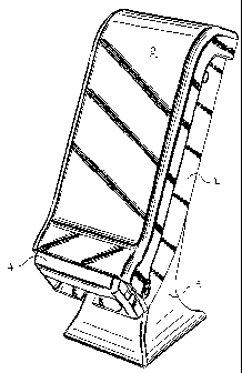
Figure 1 shows a dispenser according to an embodiment
of the invention. The Figure 1 embodiment is intended to
dispense paper napkins, but it will be appreciated that the
dispenser according to the invention could also be used to
dispense paper towels or tissues or other absorbent sheet
products.
The term Aabsorbent sheet products@ as used herein
embraces not only paper products such as paper napkins, but
also absorbent nonwoven materials not normally classed a~s
papers or tissues. Such nonwoven materials include pure
nonwovens and hybrid nonwoven/pulp webs whose properties are
similar to those of tissue paper, but which are based for
example on nonwoven or airlaid materials containing low
5
CA 02537707 2006-03-02
WO 2005/034703 PCT/US2004/024244
6
amounts of synthetic fibers, binders, wet strength agents
and the like. An example of such a material would be a
wetlaid or foam-formed hydraulically entangled nonwoven
material comprising at least 30o by weight pulp fibers and
at least 20% by weight manmade fibers or filaments.
The principal components of the dispenser in this
embodiment include a main dispenser body portion 1, that
terminates downwardly in a faceplate 4 having a dispensing
opening through which napkins are withdrawn one-by-one. In
this embodiment, the faceplate 4 is removable from the body
portion 1, as shown in Fig. 3; however, the faceplate 4
could also be formed in one piece with, or permanently
secured to, the main body portion 1.
A cover 2 closes the front of the main body portion 1,
and is openable to permit reloading of fresh napkins into
the main body portion 1. The cover 2 is preferably
transparent, so that the quantity of napkins remaining in
the dispenser can be observed without the need to open the
same; whereas the main body portion 1 is preferably opaque.
A stand 3 supports the dispenser on an underlying
horizontal surface, and also positions the dispenser at the
desired angle relative to such surface. The stand 3 is
preferably also removable from the body portion 1, as shown
in Fig. 3, which provides advantages discussed herein;
6
CA 02537707 2006-03-02
WO 2005/034703 PCT/US2004/024244
7
however, the stand 3 could also be formed in one piece with,
or permanently secured to, the main body portion 1.
In Fig. 2, it can be seen that the dispenser body in
this embodiment comprises basically two main sections, a
generally straight upstream section A, and a shorter
downstream section B, which can be straight or curved. The
upstream section A extends over at least about half of the
total length of the dispenser body from top to bottom, and
preferably more than half.
The stand 3 positions each of the sections A and B at
an oblique angle in relation to the underlying horizontal
support surface. Section A extends generally at an angle a,
wherein section B extends generally at an angle ~. To the
extent that the outer contours of the housing are not
entirely straight, as is the case for section B in this
embodiment, the measure of the angle can be taken from a
plane bisecting that portion of the napkin stack resident
within the section in question, between the front and rear
edges thereof.
Angle a is more nearly vertical than angle Vii, as is
shown in Fig. 2. Angle a is preferably in the range from
about 45° to about 85°, and more preferably about 60°, as
shown. Angle ~i is preferably in the range from about 15° to
about 60°, and more preferably about 45°, as shown.
7
CA 02537707 2006-03-02
WO 2005/034703 PCT/US2004/024244
8
As used herein, the term "sections" with reference to
the dispenser body connotes a region encompassing most or
all of the depth of the dispenser from front to back.
Accordingly, each of the upstream and downstream sections A
and B serves to turn the stack of napkins contained in the
dispenser along the respective angle at which they extend.
In particular, the upstream section A permits housing a
relatively large volume of napkins in a relatively small
area of counter space. The downstream section B, by turning
the napkin stack more toward the horizontal, permits the
dispensing opening to be positioned closer to the horizontal
support surface than would be acceptable in the case of a
vertically oriented dispenser.
Consequently, the stand 3 can be made relatively
compact, and the center of gravity of the overall dispenser
is not undesirably high. The stand 3 therefore need not be
made as large or heavy as some prior art vertically-
oriented dispensers. Furthermore, although it is within the
scope of the invention to mount the stand fixedly to the
horizontal support surface, it is normally sufficient to
have the stand 3 rest freely on such surface, in which case
some type of frictional contact elements) such as rubber
feet 20 are preferably used.
8
CA 02537707 2006-03-02
WO 2005/034703 PCT/US2004/024244
9
The exploded view of Fig. 3 shows a number of
advantageous structural details of the Fig. 1 embodiment.
All of the components are preferably formed of injection-
molded plastic. The various connecting structures of the
component parts thereby have sufficient inherent resiliency
to deform enough to enter the mating parts on the adjacent
component, for ease of assembly and disassembly.
The transparent cover 2 is connected to the main body
portion 1 via the slotted openings 15, which fit over the
flanged bosses 14 formed on the main body portion 1. Only
one opening/boss pair 14,15 is visible in Fig. 2; however,
the dispenser of this embodiment is symmetrical about a
longitudinal bisecting plane parallel to its sides. The
cover can be opened by pivoting it about the common axis of
the bosses 14 and openings 1;5. The range of angular
movement of the cover 2 relative to the main body portion 2
permits fully exposing the interior of the main body portion
1, thereby to allow unimpeded access for refilling the
dispenser.
Cleats 18 snap fit to the inside edge portions of cover
2 to hold the cover in the closed position. Those cleats
can be released by exerting inwardly-direoted pressure on
the depressions 19 formed on the outside of the main body
portion 1.
9
CA 02537707 2006-03-02
WO 2005/034703 PCT/US2004/024244
The cover 2 of this embodiment also has an inner width
slightly greater than the outer width of the main body
portion 1, so that the two components overlap in the closed
position. The main body portion 1 therefore includes a
5 laterally-outwardly projecting flange 16 on one or both
sides, which registers with the complementary-shaped edge 17
of the cover 2, and serves as a secure stop in the closed
position.
The main body portion 1 is closed at its lower end by a
10 faceplate 4 having a dispensing opening 5. The faceplate 4
cooperates with the stack of napkins held within the
dispenser to permit one-at-a-time dispensing of such
napkins, as will be described in greater detail below. The
faceplate 4 is detachably connected to the main body portion
1 by resilient cleats 12 that mate with corresponding slots
13 formed on the main body portion 1.
The main body portion 1 is detachably connected to the
stand 3 by a combination of brackets 9 on the stand that
engage slots 10 on the main body portion 1, resilient cleats
7 on the stand 3 that snap fit into corresponding openings 8
on the main body portion 1, and round projections 21 on the
stand 3 that engage openings 22 on the main body portion 1
to ensure a correct positional registration.
CA 02537707 2006-03-02
WO 2005/034703 PCT/US2004/024244
11
The main body portion 1 also includes recessed openings
11 that permit the main body portion 1 to be fastened to a
vertical support surface. In that case, the stand 3 would
not be used. The dispenser of this embodiment may therefore
be positioned on a horizontal surface by using the stand 3,
or mounted on a vertical surface, without the stand 3. This
is believed to provide a very advantageous measure of
versatility for commercial food service establishments, and
especially for fast food franchises, in that the dispenser
could be used with the stand for indoor countertop use, and
outdoors without the stand, fixed to the wall of a drive-
through lane.
Figures 4(a) and 4(b) show in a schematic manner the
napkins that it is presently preferred to use in conjunction
with the dispenser of Figs. 1-3. The napkins are
interfolded in the manner illustrated schematically in Fig.
4(a). The napkins are preferably entirely separated from
one another; however, those skilled in the art will
appreciate that the interfolded product illustrated in Fig.
4(a) will be produced using two "lanes" or webs of napkin
stock, such that alternate napkins may be interconnected by
tabs at their adjacent respective leading and trailing
edges, with the initial resistance force to withdrawal
11
CA 02537707 2006-03-02
WO 2005/034703 PCT/US2004/024244
12
through the dispensing opening 5 being sufficient to tear
the tabs and remove only a single napkin.
Each napkin is preferably "quarter-folded," meaning
that it is folded along two perpendicular lines of folding,
with each fold line preferably bisecting the sheet. An
initial sheet of napkin stock is preferably about 13" by
8'~", so the folded napkin would have dimensions of about 6~"
by ~'~". It is preferred that the napkins be rectangular
rather than square as folded, because, although the parallel
sides of the interfolded napkin stack are identical, the
perpendicular sides are not.
Therefore, the long sides of the folded napkins are
parallel to the front and back surfaces of the dispenser,
whereas the short sides of the folded napkins are parallel
to the left and right sides of the dispenser. An advantage
of this arrangement is that the napkin stack cannot be
inserted "backward" or "upside-down" into the dispenser, as
there is no distinction between the top and bottom of the
napkin stack or between the parallel sides thereof.
Figs. 4(a) and 4(b) are taken in planes parallel to
the short sides of the napkin stack. Fig. 4(b) illustrates
the point that each napkin is folded not only as shown in
the figure, but also about a perpendicular line of folding
parallel to or coincident with the plane of the drawing.
12
CA 02537707 2006-03-02
WO 2005/034703 PCT/US2004/024244
13
Therefore, the folds Visible in Figs. 4(a) and 4(b) ire
those extending across the long dimension of the napkins,
whereas the folds not visible are those extending across the
short dimension of the napkins
A quarter-fold interfolded arrangement has been
described before in connection with pop-up tissue dispensers
(see EP 0 286 538 B1 and EP 0 302 382 A1), but not
previously for napkins in a gravity-fed, downwardly opening
dispenser. Such a napkin is expected to be regarded by
users as being of relatively high quality, because the
presence of four panels permits conferring sufficient
aggregate strength and flexibility to the napkin while using
stock web material having a relatively low basis weight,
which confers advantageous properties of drape and hand feel
to the napkin.
In use, the napkin stack is loaded into the dispenser
with the cover 2 in open position, after which the cover 2
is closed. A first napkin is withdrawn in whole or in part
through the dispensing opening 5, with the aid of the side
extension 6 thereof. The interfolding causes two adjacent
panels of the next napkin to project through the dispensing
opening, such that a user will be able to take only one
napkin at a time. This dispensing mode discourages users
13
CA 02537707 2006-03-02
WO 2005/034703 PCT/US2004/024244
14
from withdrawing more napkins than are needed, and
correspondingly reduces waste.
When the dispenser is almost empty, the transparent
cover 2 will reveal that condition to employees of the
establishment, so that the dispenser can be refilled.
While the present invention has been described in
connection with various preferred embodiments thereof, it is
to be understood that those embodiments are provided merely
to illustrate the invention, and should not be used as a
pretext to limit the scope of protection conferred by the
true scope and spirit of the appended claims.
14