Language selection

Search

Patent 2537751 Summary

Third-party information liability

Some of the information on this Web page has been provided by external sources. The Government of Canada is not responsible for the accuracy, reliability or currency of the information supplied by external sources. Users wishing to rely upon this information should consult directly with the source of the information. Content provided by external sources is not subject to official languages, privacy and accessibility requirements.

Claims and Abstract availability

Any discrepancies in the text and image of the Claims and Abstract are due to differing posting times. Text of the Claims and Abstract are posted:

  • At the time the application is open to public inspection;
  • At the time of issue of the patent (grant).
(12) Patent Application: (11) CA 2537751
(54) English Title: FURNACE AND PROCESS FOR DRAWING RADIATION RESISTANT OPTICAL FIBER
(54) French Title: FOUR ET PROCEDE POUR L'EXTRUSION DE FIBRE OPTIQUE RESISTANT AU RAYONNEMENT
Status: Deemed Abandoned and Beyond the Period of Reinstatement - Pending Response to Notice of Disregarded Communication
Bibliographic Data
(51) International Patent Classification (IPC):
  • B29C 55/30 (2006.01)
  • B29C 71/00 (2006.01)
(72) Inventors :
  • KUCZMA, ANDREW S. (United States of America)
(73) Owners :
  • WEATHERFORD/LAMB, INC.
(71) Applicants :
  • WEATHERFORD/LAMB, INC. (United States of America)
(74) Agent: DEETH WILLIAMS WALL LLP
(74) Associate agent:
(45) Issued:
(22) Filed Date: 2006-02-27
(41) Open to Public Inspection: 2006-08-28
Examination requested: 2006-02-27
Availability of licence: N/A
Dedicated to the Public: N/A
(25) Language of filing: English

Patent Cooperation Treaty (PCT): No

(30) Application Priority Data:
Application No. Country/Territory Date
60/657,161 (United States of America) 2005-02-28

Abstracts

English Abstract


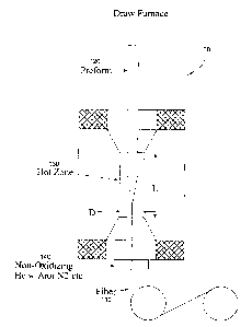
Apparatus and methods to fabricate a radiation hardened optical fiber from a
preform are provided. Various parameters affecting the draw process are
controlled to
optimize the radiation resistance of the resulting fiber. An annealing zone
may be
provided to allow a drawn fiber exiting a primary hot zone to undergo an
annealing
process which may increase radiation resistance.


Claims

Note: Claims are shown in the official language in which they were submitted.


What is claimed is:
1. An apparatus for drawing an optical fiber from an optical fiber preform,
comprising:
a first furnace for heating a first zone in which the preform is heated to
draw an
optical fiber therefrom; and
an annealing zone through which the drawn fiber passes after exiting the first
zone to undergo an annealing process.
2. The apparatus of claim 1, further comprising a second furnace to heat the
annealing zone at a different temperature than the first furnace heats the
first zone.
3. A method for drawing an optical fiber from an optical fiber preform,
comprising:
heating the preform in a first zone at a first temperature to draw an optical
fiber
therefrom; and
annealing the drawn fiber in an annealing zone after it exits the first zone,
wherein the annealing zone is maintained at a second temperature.
6

Description

Note: Descriptions are shown in the official language in which they were submitted.


CA 02537751 2006-02-27
FURNACE AND PROCESS FOR DRAWING
RADIATION RESISTANT OPTICAL FIBER
BACKGROUND OF THE INVENTION
Field of the Invention
Embodiments of the present invention generally relate to optical fibers and,
more
particularly, to a furnace and process for drawing optical fibers from a
preform.
Description of the Related Art
Optical fibers and other type waveguides are typically formed by heating and
drawing an optical fiber preform. The preform typically includes a core and
surrounding
cladding, with appropriate dopants to achieve desired characteristics of the
resulting
drawn fiber.
Standard telecommunications optical fibers are highly susceptible to optical
signal losses caused by nuclear or ionizing radiation. Careful selection of
dopants and
process conditions during glass fabrication have been shown to improve
radiation
resistance. For example, U.S. Pat. No. 5,509,101 to Gilliad et al., describes
a silica
fiber doped with fluorine doping in the core and a portion of the cladding
drawn at low
draw tension, while U.S. Pat. No. 5,681,365 to Gilliad et al. describes a
silica fiber
doped with fluorine doping in the core and a portion of the cladding drawn at
low draw
tension with additional germanium doping in a portion of the cladding. Both of
these
patents are hereby incorporated by reference in their entirety.
Conditions of the final fiber draw process are also important in optimizing
the
radiation resistance of the final fiber article. Improper fiber draw
conditions can be
detrimental to radiation resistance. While this phenomena is not completely
understood, it is believed that non-optimized draw conditions cause internal
stress
within the waveguide. These stresses may place the chemical bonds of the glass
matrix under strain. Radiation can rupture these strained bonds causing defect
sites
within the glass leading to increased optical signal attenuation.
1

CA 02537751 2006-02-27
Accordingly, what is needed are improved apparatus and methods for drawing
radiation resistant optical fiber.
SUMMARY OF THE INVENTION
Embodiments of the present invention generally provide apparatus and methods
for drawing radiation resistant optical fiber.
One embodiment provides an apparatus for drawing an optical fiber from an
optical fiber preform. The apparatus generally includes a first furnace for
heating a first
zone in which the preform is heated to draw an optical fiber therefrom and an
annealing
zone through which the drawn fiber passes after exiting the first zone to
undergo an
annealing process.
Another embodiment provides a method for drawing an optical fiber from an
optical fiber preform. The method generally includes heating the preform in a
first zone
at a first temperature to draw an optical fiber therefrom and annealing the
drawn fiber in
an annealing zone after it exits the first zone, wherein the annealing zone is
maintained
at a second temperature.
BRIEF DESCRIPTION OF THE DRAWINGS
So that the manner in which the above recited features of the present
invention
can be understood in detail, a more particular description of the invention,
briefly
summarized above, may be had by reference to embodiments, some of which are
illustrated in the appended drawings. It is to be noted, however, that the
appended
drawings illustrate only typical embodiments of this invention and are
therefore not to
be considered limiting of its scope, for the invention may admit to other
equally effective
embodiments.
FIG. 1 illustrates an exemplary draw furnace, in accordance with one
embodiment of the present invention;
2

CA 02537751 2006-02-27
FIG. 2 illustrates an exemplary draw furnace, in accordance with another
embodiment of the present invention; and
FIG. 3 illustrates exemplary preform compositions, in accordance with one
embodiment of the present invention.
DETAILED DESCRIPTION OF THE PREFERRED EMBODIMENT
Embodiments of the present invention provide various apparatus and methods to
fabricate a radiation hardened optical fiber from a preform. Various
parameters
affecting the draw process are controlled to optimize the radiation resistance
of the
resulting fiber. In some cases an annealing zone may be provided at the bottom
of a
draw furnace, allowing a drawn optical fiber to undergo an annealing process
after
exiting a primary hot zone. This annealing process may relax internal stresses
and
increase radiation resistance of the drawn fiber.
AS EXEMPLARY DRAW FURNACE
FIG. 1 illustrates an exemplary draw furnace in accordance with embodiments of
the present invention that may be used to draw a radiation hardened fiber 110
from a
preform 120. As illustrated, the preform 120 is fed into the furnace and
enters a hot
zone 130, where the preform softens and begins to melt. Below (e.g., at the
bottom of
a draw tower), the fiber 110 may be pulled and wound onto spools.
For some embodiments, the preform 120 may be doped with materials chosen to
enhance radiation resistance. For example, for some embodiments, the preform
120
may have a pure silica (Si02) core with a fluorine doped silica cladding, and
may be
drawn into a single or multi-mode fiber. The preform 120 may be drawn at high
temperature and low draw speed resulting in low draw tension. Resultant fiber
110
drawn from this process has shown to have promising radiation resistance. This
reduction in radiation sensitivity may result from a reduction in internal
bond strain
within the fiber optical core, at the corelclad interface and/or in the
cladding.
3

CA 02537751 2006-02-27
For some embodiments, the dimension of the hotzone 130 may be chosen in an
effort to heat the preform evenly. As an example, for some embodiments, the
hotzone
130 may have a diameter (D) that is approximately 2 to 3 times greater than
that of the
glass preform. For one embodiment, the hotzone 130 may be approximately 120mm
in
length (L) x 45mm in diameter (D). In addition, the fiber 110 may exit the
furnace
through a non-oxidizing gas atmosphere element 140 that may include helium
(He)
which has high a heat transfer coefficient. In some cases, Argon (Ar) or
nitrogen (N2)
may also be added in the non-oxidizing gas atmosphere element 140.
Another feature which may help reduce radiation sensitivity caused by internal
stress is the addition of a secondary heating or "annealing" zone 150 below
the hotzone
of the fiber draw furnace. As illustrated in FIG. 2, for some embodiments,
this
annealing zone can be in the form of an tube extension at the bottom of the
draw
furnace 100 or may actually be another (secondary) furnace, or a combination
of the
two.
In any case, this annealing zone may allow the molten fiber to heat-soak until
its
temperature is even throughout. The time of the annealing may be controlled by
the
temperature and length of the annealing zone and may vary depending on the
parameters of the fiber being drawn (e.g., fiber thickness, materials, etc.).
The
annealing zone may allow the fiber to slowly cool at a predetermined rate
which may
relax internal stresses and may increase radiation resistance. As illustrated,
the fiber
110 may exit the annealing zone 150 through a non-oxidizing gas atmosphere
element
140.
FIG. 3 shows an end view of the preform 120, along with a table of exemplary
compositions of the core 122 and cladding 124. As illustrated, conventional
radiation
hardened fibers may be formed with preforms having fluorine doped silica cores
and
fluorine andlor germania doped cladding. However, utilizing the draw processes
described herein, fibers of comparable radiation resistance may be achieved
from
preforms with pure silica cores. Eliminating the step of doping the core may
facilitate
the manufacturing process and reduce cost.
4

CA 02537751 2006-02-27
CONCLUSION
While the foregoing is directed to embodiments of the present invention, other
and further embodiments of the invention may be devised without departing from
the
basic scope thereof, and the scope thereof is determined by the claims that
follow.

Representative Drawing
A single figure which represents the drawing illustrating the invention.
Administrative Status

2024-08-01:As part of the Next Generation Patents (NGP) transition, the Canadian Patents Database (CPD) now contains a more detailed Event History, which replicates the Event Log of our new back-office solution.

Please note that "Inactive:" events refers to events no longer in use in our new back-office solution.

For a clearer understanding of the status of the application/patent presented on this page, the site Disclaimer , as well as the definitions for Patent , Event History , Maintenance Fee  and Payment History  should be consulted.

Event History

Description Date
Inactive: Dead - No reply to s.30(2) Rules requisition 2011-04-26
Application Not Reinstated by Deadline 2011-04-26
Deemed Abandoned - Failure to Respond to Maintenance Fee Notice 2011-02-28
Amendment Received - Voluntary Amendment 2010-04-27
Inactive: Abandoned - No reply to s.30(2) Rules requisition 2010-04-26
Amendment Received - Voluntary Amendment 2010-04-26
Inactive: S.30(2) Rules - Examiner requisition 2009-10-26
Amendment Received - Voluntary Amendment 2009-09-16
Amendment Received - Voluntary Amendment 2009-05-13
Inactive: S.29 Rules - Examiner requisition 2008-12-10
Inactive: S.30(2) Rules - Examiner requisition 2008-12-10
Amendment Received - Voluntary Amendment 2008-07-04
Inactive: S.30(2) Rules - Examiner requisition 2008-01-04
Inactive: S.29 Rules - Examiner requisition 2008-01-04
Letter Sent 2007-03-01
Inactive: Single transfer 2007-01-23
Application Published (Open to Public Inspection) 2006-08-28
Inactive: Cover page published 2006-08-27
Inactive: IPC assigned 2006-08-03
Inactive: First IPC assigned 2006-08-03
Inactive: IPC assigned 2006-08-03
Amendment Received - Voluntary Amendment 2006-07-20
Inactive: Courtesy letter - Evidence 2006-03-28
Inactive: Filing certificate - RFE (English) 2006-03-24
Filing Requirements Determined Compliant 2006-03-24
Letter Sent 2006-03-24
Application Received - Regular National 2006-03-24
Request for Examination Requirements Determined Compliant 2006-02-27
All Requirements for Examination Determined Compliant 2006-02-27

Abandonment History

Abandonment Date Reason Reinstatement Date
2011-02-28

Maintenance Fee

The last payment was received on 2010-02-02

Note : If the full payment has not been received on or before the date indicated, a further fee may be required which may be one of the following

  • the reinstatement fee;
  • the late payment fee; or
  • additional fee to reverse deemed expiry.

Please refer to the CIPO Patent Fees web page to see all current fee amounts.

Fee History

Fee Type Anniversary Year Due Date Paid Date
Application fee - standard 2006-02-27
Request for examination - standard 2006-02-27
Registration of a document 2007-01-23
MF (application, 2nd anniv.) - standard 02 2008-02-27 2008-01-21
MF (application, 3rd anniv.) - standard 03 2009-02-27 2009-01-22
MF (application, 4th anniv.) - standard 04 2010-03-01 2010-02-02
Owners on Record

Note: Records showing the ownership history in alphabetical order.

Current Owners on Record
WEATHERFORD/LAMB, INC.
Past Owners on Record
ANDREW S. KUCZMA
Past Owners that do not appear in the "Owners on Record" listing will appear in other documentation within the application.
Documents

To view selected files, please enter reCAPTCHA code :


To view images, click a link in the Document Description column. To download the documents, select one or more checkboxes in the first column and then click the "Download Selected in PDF format (Zip Archive)" or the "Download Selected as Single PDF" button.

List of published and non-published patent-specific documents on the CPD .

If you have any difficulty accessing content, you can call the Client Service Centre at 1-866-997-1936 or send them an e-mail at CIPO Client Service Centre.


Document
Description 
Date
(yyyy-mm-dd) 
Number of pages   Size of Image (KB) 
Description 2006-02-27 5 188
Abstract 2006-02-27 1 11
Drawings 2006-02-27 3 56
Claims 2006-02-27 1 20
Representative drawing 2006-08-08 1 6
Cover Page 2006-08-14 1 32
Description 2008-07-04 5 188
Claims 2008-07-04 2 41
Claims 2009-05-13 2 59
Acknowledgement of Request for Examination 2006-03-24 1 190
Filing Certificate (English) 2006-03-24 1 168
Request for evidence or missing transfer 2007-02-28 1 101
Courtesy - Certificate of registration (related document(s)) 2007-03-01 1 105
Reminder of maintenance fee due 2007-10-30 1 113
Courtesy - Abandonment Letter (R30(2)) 2010-07-19 1 164
Courtesy - Abandonment Letter (Maintenance Fee) 2011-04-26 1 173
Correspondence 2006-03-24 1 27
Fees 2008-01-21 1 33
Fees 2009-01-22 1 34
Fees 2010-02-02 1 38