Language selection

Search

Patent 2538129 Summary

Third-party information liability

Some of the information on this Web page has been provided by external sources. The Government of Canada is not responsible for the accuracy, reliability or currency of the information supplied by external sources. Users wishing to rely upon this information should consult directly with the source of the information. Content provided by external sources is not subject to official languages, privacy and accessibility requirements.

Claims and Abstract availability

Any discrepancies in the text and image of the Claims and Abstract are due to differing posting times. Text of the Claims and Abstract are posted:

  • At the time the application is open to public inspection;
  • At the time of issue of the patent (grant).
(12) Patent: (11) CA 2538129
(54) English Title: FOLDABLE WATER TANK
(54) French Title: RESERVOIR D'EAU REPLIABLE
Status: Expired and beyond the Period of Reversal
Bibliographic Data
(51) International Patent Classification (IPC):
  • B65D 90/02 (2019.01)
  • B65D 06/08 (2006.01)
  • B65D 06/10 (2006.01)
  • B65D 06/28 (2006.01)
  • B65D 08/04 (2006.01)
  • B65D 08/12 (2006.01)
  • B65D 88/52 (2006.01)
(72) Inventors :
  • CHRISTENSEN, JAN (United States of America)
(73) Owners :
  • ELDRED CORPORATION DBA FOL-DA-TANK COMPANY
(71) Applicants :
  • ELDRED CORPORATION DBA FOL-DA-TANK COMPANY (United States of America)
(74) Agent: SMART & BIGGAR LP
(74) Associate agent:
(45) Issued: 2009-04-28
(86) PCT Filing Date: 2004-02-19
(87) Open to Public Inspection: 2005-05-12
Examination requested: 2006-03-07
Availability of licence: N/A
Dedicated to the Public: N/A
(25) Language of filing: English

Patent Cooperation Treaty (PCT): Yes
(86) PCT Filing Number: PCT/US2004/003356
(87) International Publication Number: US2004003356
(85) National Entry: 2006-03-07

(30) Application Priority Data:
Application No. Country/Territory Date
10/677,740 (United States of America) 2003-10-03

Abstracts

English Abstract


A foldable water tank comprises a foldable receptacle having a bottom wall and
vertical sidewalls, the sidewalls being inclined inwardly; and a plurality of
support structures connected to the sidewalls to support the sidewalls in the
inclined position.


French Abstract

L'invention concerne un réservoir d'eau repliable comprenant une base repliable formée d'un fond et de parois latérales verticales, lesdites parois latérales étant inclinées vers l'intérieur, et une pluralité de structures de support connectées aux parois latérales de manière à supporter celles-ci en position inclinée.

Claims

Note: Claims are shown in the official language in which they were submitted.

CLAIMS:
1. A foldable water tank, comprising:
a) a foldable receptacle having a bottom wall and vertical
sidewalls, said sidewalls being inclined inwardly;
b) a plurality of support structures connected to said
sidewalls to support said sidewalls in the inclined position;
c) said receptacle is substantially a truncated pyramid
having a plurality of upper corners; and
d) each of said support structures is connected to a
respective said upper corner.
2. A foldable water tank as in claim 1, wherein said support
structures are disposed within said receptacle.
3. A foldable water tank as in claim 1, wherein said support
structures are disposed outside said receptacle.
4. A foldable receptacle as in claim 1, wherein:
a) said each of said support structures includes a
vertical member inclined inwardly toward the interior of said
receptacle; and
b) a clip disposed at an upper end of said vertical member
to hook into an opening in said sidewall.
5. A foldable receptacle as in claim 1, wherein said support
structures include tubular members.
6. A foldable receptacle as in claim 1, wherein each of said
support structures comprises:
a) first, second and third tubular members pivotally
joined at their first ends;
b) said tubular members having a storage position wherein
said tubular members are adjacent each other; and
-9-

c) said tubular members having a deployed position wherein
said tubular members are spread apart from each other to form
acute angles between each other at said first ends.
7. A foldable water tank as in claim 6, wherein:
a) said first member is inclined vertically when deployed;
b) first brace connected to said first and second tubular
member; and
c) second brace connected to said first and third tubular
member.
8. A foldable water tank as in claim 7, wherein
a) said first and second braces are pivotally connected to
said second and third tubular members, respectively; and
b) said first and second braces are removably secured to
said first tubular member.
9. A foldable water tank as in claim 1, wherein said
receptacle has an open top.
10. A foldable water tank as in claim 1, wherein said
receptacle includes an outlet or inlet flange.
11. A foldable water tank as in claim 6, and further
comprising:
a) a bag configured to be carried by a person; and
b) said receptacle when folded and said support structures
in said stored position are configured to fit inside said bag.
12. A foldable water tank as in claim 4, wherein:
a) said receptacle includes a plurality of sleeves; and
b) said vertical member of each support structures is
received within a respective sleeve.
13. A foldable water tank comprising:
-10-

a) a foldable receptacle having a bottom wall and vertical
sidewalls, said sidewalls being inclined inwardly; and
b) a plurality of support structures removably connected
to said sidewalls to support said sidewalls in the inclined
position;
c) each of said support structures including a vertical
member secured to a base, said vertical member being inclined
in the direction of said sidewalls; and
d) said support structures are disposed within said
receptacle.
14. A foldable water tank as in claim 13, wherein said support
structures are tubular.
15. A foldable water tank as in claim 13, and further
comprising means for folding said support structures into a
compact configuration.
-11-

Description

Note: Descriptions are shown in the official language in which they were submitted.


CA 02538129 2006-03-07
WO 2005/042379 PCT/US2004/003356
FOLDABLE WATER TANK
FIELD OF THE INVENTION
The present invention relates generally to a water tank,
and specifically to a lightweight foldable water tank that can
be stowed into a compact shape to facilitate transport to the
scene of a fire.
BACKGROUND OF THE INVENTION
There is a need for larger portable water tanks to keep
rural fire protection insurance down. However, the stowed tank
sizes must be kept small to be accommodated on the top or sides
of fire trucks. When the tanks reach 14-20 ft. long, storage
can become a problem.
L5 Portability is essential to forest fighters in remote
areas. There is a need for lightweight portable tanks that can
be shipped by helicopters in quantities and quickly assembled on
site by one person.
-1-

CA 02538129 2006-03-07
WO 2005/042379 PCT/US2004/003356
OBJECTS AND SUMMARY OF THE INVENTION
It is an object of the present invention to provide a
foldable water tank that can be stored in a relatively compact
size to facilitate transport to the scene of a fire.
It is another object of the present invention to provide a
foldable water tank that is relatively quick to assemble at the
site of a fire.
It is still another object of the present invention to
provide a foldable water tank that can be shipped to remote
areas by helicopters and quickly assembled on site.
It is still another object of the present~invention to
provide a foldable water tank for use in rural and forestry
areas where water supply is limited.
It is another object of the present invention to provide a
foldable water tank that is Compact in size so that it can be
carried on a fire tanker truck when not in use and then deployed
at the scene of a fire in a rural area for water storage.
In summary, the present invention provides a foldable water
tank, comprising a foldable receptacle having a bottom wall and
vertical sidewalls, the sidewalls being inclined inwardly; and a
plurality of support structures connected to the sidewalls to
support the sidewalls in the inclined position.
These and other objects of the present invention will
become apparent from the following detailed description.
-2-

CA 02538129 2006-03-07
WO 2005/042379 PCT/US2004/003356
. BRIEF DESCRIPTIONS OF THE DRAWINGS
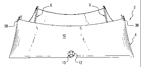
Fig. 1 is a perspective view of a foldable water tank made
in accordance with the present invention.
Fig. 2 is top plan view of Fig. 1.
Fig. 3 is a perspective view of a support structure made in
accordance with the present invention and shown in a deployed
position.
Fig. 4 is fragmentary perspective view of a corner portion
of the support structure of Fig. 3.
Fig. 5 shows the support structure of Fig. 3. in a stowed,
folded position.
Fig. 6 is a top plan view of Fig. 1 when the tank is filled
with water.
Fig. 7 is a cross-sectional view taken along line 7-7 of
Fig. 6.
Fig. 8 is a perspective view of a foldable water tank,
showing the deployed support structures disposed outside the
receptacle.
Fig. 9 is an enlarged detail view of a corner portion of
the tank of Fig. 8.
Figs. 10 and 11 show the water tank of Fig. 1 being
unfolded and deployed.
Fig. 12 shows the water tank of Fig. 1 in a stowed
configuration for placement inside a carrying bag.
Fig. 13 shows one person carrying the bag of Fig. 12 with
the folded water tank stowed configuration inside.
-3-

CA 02538129 2006-03-07
WO 2005/042379 PCT/US2004/003356
Figs. 14 and 15 shows the folding of the receptacle of
Fig. 1 into thirds for stowage.
Fig. 16 shows the placement of the support structures of
Fig. 5 over a tarp for stowage.
DETAILED DESCRIPTION OF THE INVENTION
A foldable water tank 2 made in accordance with the present
invention is disclosed in Figs. 1 and 2 in a deployed position.
The water tank 2 includes a flexible receptacle 4 and a
plurality of support structures 6 disposed within the receptacle
4. The receptacle 4 includes a bottom wall 8 and inwardly
inclined side walls 10, forming a truncated pyramid with four
upper corners. The receptacle 4 is made from conventional water
tight material. The receptacle 4 has a standard fire department
threaded flange 12 for connection to a filling or pumper truck
(not shown) for filling or dispensing. The receptacle 4 may
also be drained through the flange 12. The flange 12 is closed
with a removable threaded cap 13 if not connected when not in
use. The receptacle 4 has an open top to advantageously
facilitate filling, for example, from above by a bucket-carrying
helicopter. Although the truncated pyramid is shown as having a
square base wall, it should be understood that it can be other
shapes with the corresponding inclined sidewalls. The support
structures 6 are preferably disposed inside the receptacle 4,
but may also be disposed outside.
-4-

CA 02538129 2006-03-07
WO 2005/042379 PCT/US2004/003356
Referring to Figs. 3 and 4, each support structure 6
include base members 14 and 16 and vertical member 18 joined at
their one ends with pivots 20 so that the support structure may
be collapsed into a compact configuration, as best shown in Fig.
5. It should be understood that the pivots 20 provide the means
for collapsing the support structures 6 into a compact
configuration. The pivots 20 may be of the ratcheting type of
standard construction that selectively locks as the members 14,
16 and 18 are expanded so that the structure holds its deployed
position. A brace 22 pivotably connected to the base members 16
and removably secured to the vertical member 18 may be used to
provide further rigidity to the structure in the deployed
position. Similarly, a brace 24 pivotably connected to the base
member 14 and removably secured to the vertical member 18 may
also be provided. A pin 26 is used to removably secure the
brace 22 to the vertical member 18 through a hole 28 in the
vertical member 18. Similarly, a pin 30 is removably secured in
a hole 28 in the vertical member 18. Straps 32 and 34, one end
of each is respectively secured to the brace members 22 and 24
are respectively secured to the pins 26 and 30 to prevent loss
of the pins when the support structure 6 is folded and stowed
away. The members 14, 16 and 18 are preferably lightweight
tubular aluminum, but other materials and shapes may be used.
The upper end of each vertical member 18 includes a clip 36 for
hooking into a corresponding reinforced opening 38 in the
receptacle 4 located at each upper corner of the truncated
-5-

CA 02538129 2006-03-07
WO 2005/042379 PCT/US2004/003356
pyramid.
Since a support structure 6 is not connected to any of the
other support structure, there are less hardware required,
thereby making the support structures in the aggregate
relatively lightweight.
The vertical member 18 is inclined inwardly towards the
base members 14 and 16, such that an acute angle is formed
between the vertical member 18 and each of the base members 14
and 16. The inclination of the vertical member 18 is
substantially, but not necessarily, the same as the inclination
of the side walls 10 of the receptacle 4. The inclination of
the vertical member 18 advantageously provides a stable support
so that the support structure 6 remains upright during use to
support the side walls 10 in the upright position. It should be
understood that the inclined vertical member 18 and the
supporting base members 14 and 16 provide the means to support
the sidewalls in the inclined position.
When the receptacle 4 is filled with water, the side walls
10 bulge out, as best shown in Figs. 6 and 7. The water exerts
pressure on the side walls and the resulting forces are
transferred to the support structures 6 to keep the side walls
in the upright position.
Referring to Figs. 8 and 9, the support structures 6 are
disclosed as being disposed outside the receptacle 4. In this
embodiment, the receptacle 4 is preferably provided with a
sleeve 40 along each intersection the sidewall 10 with the
-6-

CA 02538129 2006-03-07
WO 2005/042379 PCT/US2004/003356
adjacent sidewall. The sleeve 4 advantageously provides greater
stability to the support structures 6 when in use.
Referring to Figs. 10 and 11, the water tank 2 is assembled
by laying out the receptacle 4 on a relatively flat surface and
placing the support structures 6 in the vicinity of each corner
of the receptacle 4. Each support structures 6 is quickly
deployed into its expanded position by spreading the base
members 14 and 16 apart about its pivot 20, as generally shown
by the arrow 42, rotating the vertical member 18 in the
direction of the arrow 44 and securing the braces 22 and 24 to
the vertical member 18, as best shown in Fig. 4. The deployed
support structure 6 is then placed inside the receptacle 4 and
the respective corner of the receptacle 4 is then lifted and
secured to the clip 36 at the upper end of each vertical member
18.
A bag 46 is preferably provided to store the receptacle 4
and the support structures 6 in a compact, portable manner. The
receptacle 4 is~first folded and then rolled. After folding
sidewalls 10 onto the base wall 8, as shown in Fig. 10, the
receptacle 4 is then further folded into on another, such as
into thirds, as shown in Figs. 14 and 15. The receptacle 4 is
then rolled into a compact configuration and secured with a
strap 48 as shown in Fig. 12.
The support structures 6 are placed on a sheet material,
such as a tarp 50, as shown in Fig. 16, and then rolled into a
compact shape as shown in Fig. 12 held by a strap 52. The

CA 02538129 2006-03-07
WO 2005/042379 PCT/US2004/003356
receptacle 4 and the support structures 6 in the configuration
shown in Fig. 12 are then placed inside the bag 46 for storage
or transport. The bag 46 has handle straps 54 for convenient
handling by a single person. Additional straps 56 at each end
of the bag are also provided for convenient handling by two
people.
The foldable water tank 2 can be made with a capacity range
of 500-2000 gallons while still maintaining its portability and
compactness. The water tank 2 can be assembled by one person
relatively quickly.
While this invention has been described as having preferred
design, it is understood that it is capable of further
modification, uses and/or adaptations following in general the
principle of the invention and including such departures from
the present disclosure as come within known or customary
practice in the art to which the invention pertains, and as may
be applied to the essential features set forth, and fall within
the scope of the invention or the limits of the appended claims.
_g_

Representative Drawing
A single figure which represents the drawing illustrating the invention.
Administrative Status

2024-08-01:As part of the Next Generation Patents (NGP) transition, the Canadian Patents Database (CPD) now contains a more detailed Event History, which replicates the Event Log of our new back-office solution.

Please note that "Inactive:" events refers to events no longer in use in our new back-office solution.

For a clearer understanding of the status of the application/patent presented on this page, the site Disclaimer , as well as the definitions for Patent , Event History , Maintenance Fee  and Payment History  should be consulted.

Event History

Description Date
Inactive: IPC deactivated 2020-02-15
Inactive: First IPC assigned 2019-05-01
Inactive: IPC assigned 2019-05-01
Inactive: IPC expired 2019-01-01
Time Limit for Reversal Expired 2013-02-19
Letter Sent 2012-02-20
Grant by Issuance 2009-04-28
Inactive: Cover page published 2009-04-27
Pre-grant 2009-02-06
Inactive: Final fee received 2009-02-06
Notice of Allowance is Issued 2008-10-15
Letter Sent 2008-10-15
Notice of Allowance is Issued 2008-10-15
Inactive: IPC assigned 2008-09-17
Inactive: Approved for allowance (AFA) 2008-09-09
Amendment Received - Voluntary Amendment 2008-04-23
Inactive: S.30(2) Rules - Examiner requisition 2007-12-19
Amendment Received - Voluntary Amendment 2007-11-07
Inactive: S.30(2) Rules - Examiner requisition 2007-09-06
Letter Sent 2006-07-14
Amendment Received - Voluntary Amendment 2006-07-11
Inactive: Single transfer 2006-06-08
Inactive: Cover page published 2006-05-11
Inactive: Courtesy letter - Evidence 2006-05-09
Inactive: Acknowledgment of national entry - RFE 2006-05-08
Letter Sent 2006-05-08
Application Received - PCT 2006-03-28
National Entry Requirements Determined Compliant 2006-03-07
Request for Examination Requirements Determined Compliant 2006-03-07
All Requirements for Examination Determined Compliant 2006-03-07
Application Published (Open to Public Inspection) 2005-05-12

Abandonment History

There is no abandonment history.

Maintenance Fee

The last payment was received on 2009-01-28

Note : If the full payment has not been received on or before the date indicated, a further fee may be required which may be one of the following

  • the reinstatement fee;
  • the late payment fee; or
  • additional fee to reverse deemed expiry.

Patent fees are adjusted on the 1st of January every year. The amounts above are the current amounts if received by December 31 of the current year.
Please refer to the CIPO Patent Fees web page to see all current fee amounts.

Fee History

Fee Type Anniversary Year Due Date Paid Date
Request for examination - standard 2006-03-07
Basic national fee - standard 2006-03-07
MF (application, 2nd anniv.) - standard 02 2006-02-20 2006-03-07
Registration of a document 2006-06-08
MF (application, 3rd anniv.) - standard 03 2007-02-19 2007-01-17
MF (application, 4th anniv.) - standard 04 2008-02-19 2008-02-06
MF (application, 5th anniv.) - standard 05 2009-02-19 2009-01-28
Final fee - standard 2009-02-06
MF (patent, 6th anniv.) - standard 2010-02-19 2010-02-04
MF (patent, 7th anniv.) - standard 2011-02-21 2011-01-25
Owners on Record

Note: Records showing the ownership history in alphabetical order.

Current Owners on Record
ELDRED CORPORATION DBA FOL-DA-TANK COMPANY
Past Owners on Record
JAN CHRISTENSEN
Past Owners that do not appear in the "Owners on Record" listing will appear in other documentation within the application.
Documents

To view selected files, please enter reCAPTCHA code :


To view images, click a link in the Document Description column. To download the documents, select one or more checkboxes in the first column and then click the "Download Selected in PDF format (Zip Archive)" or the "Download Selected as Single PDF" button.

List of published and non-published patent-specific documents on the CPD .

If you have any difficulty accessing content, you can call the Client Service Centre at 1-866-997-1936 or send them an e-mail at CIPO Client Service Centre.


Document
Description 
Date
(yyyy-mm-dd) 
Number of pages   Size of Image (KB) 
Drawings 2006-03-06 9 171
Description 2006-03-06 8 285
Claims 2006-03-06 4 121
Abstract 2006-03-06 1 55
Representative drawing 2006-03-06 1 6
Claims 2007-11-06 3 85
Claims 2008-04-22 3 81
Representative drawing 2009-04-13 1 7
Acknowledgement of Request for Examination 2006-05-07 1 190
Notice of National Entry 2006-05-07 1 230
Courtesy - Certificate of registration (related document(s)) 2006-07-13 1 105
Commissioner's Notice - Application Found Allowable 2008-10-14 1 163
Maintenance Fee Notice 2012-04-01 1 172
PCT 2006-03-06 3 87
Correspondence 2006-05-07 1 26
Fees 2007-01-16 1 28
Fees 2008-02-05 1 34
Correspondence 2009-02-05 1 35
Fees 2009-01-27 1 35
Fees 2010-02-03 1 35
Fees 2011-01-24 1 35