Note: Descriptions are shown in the official language in which they were submitted.
CA 02538278 2006-03-01
INTEGRAL TORTUOUS PATH RECEPTACLE COVER
BACKGROUND OF THE INVENTION
The present invention relates to a cover for a medical waste disposal
receptacle and a method of manufacturing a cover for a medical waste disposal
receptacle. More specifically, the present invention relates to medical waste
disposal
receptacles having a flexibly pivoted top closure lid and, more particularly,
to a
receptacle cover having an integral pivoted lid portion and a body portion
having an
integral tortuous path access opening.
Various types of containers for hospital use have been developed for
receiving medical waste in a surgical operating room, pre-op or post-op room,
a
io patient's room, or in other clinical or non-clinical settings in which
medical waste is
generated. These containers are particularly designed to protect the user of
such
containers, such as doctors, nurses, or other hospital personnel, from the
hospital
waste products that may be disposed therein. Such hospital waste products
might
include surgical sharps, such as needles, syringes, scalpel blades, or the
like, or might
include gauzes, bandages, or sponges. It is important to prevent the user of a
sharps
container from being accidentally cut or punctured by its contents.
Examples of such containers include those shown in U.S. Pat. No.
5,058,764, entitled "Mounting Bracket Having A Hidden Lock For A Sharps
Collection
System"; U.S. Pat. No. 5,080,251, entitled "Tortuous Path In-Patient Room
Medical
Waste Disposal Container"; and U.S. Pat. No. 5,494,186, entitled "Wall Mounted
Medical Waste Disposal Container With Pivoted Top Closure Lid."
While the prior art containers provide a desired level of protection, they
generally require various components to be formed separately and thereafter
CA 02538278 2013-03-22
, .
- 2 -
assembled. These additional steps add cost and complexity to the manufacturing
process.
SUMMARY OF THE INVENTION
According to a broad aspect, the invention provides a cover for a medical
waste disposal receptacle, the receptacle defining a receptacle open end, the
cover
comprising (a) a body portion including a covering surface configured to
substantially close the receptacle open end except for an access opening
therethrough defined by a front opening edge, a rear opening edge, and opposed
side edges extending between the front and rear opening edges, the body
portion
further including integrally formed, fixed first and second sloped slide
surfaces
depending from the covering surface adjacent the access opening and (b) a lid
portion hingedly connected to the covering surface proximate the rear opening
edge, the lid portion having a locking tab extending from a support rib;
wherein the
lid portion is adapted to pivot relative to the covering surface to a closed
position in
which the access opening is blocked; wherein the locking tab locks the lid
portion in
the closed position by extending through a locking bore located on the first
sloped
slide surface to engage a shoulder; wherein the support rib is positioned
outside the
locking bore when the lid portion is locked in the closed position; wherein
the first
and second sloped slide surfaces are axially spaced in non-overlapping
relation to
define a tortuous path extending from the access opening; and wherein the body
portion includes a plurality of locking tabs and corresponding apertures in
alignment
with the locking tabs such that all components of the cover allow a singular
linear
separation of the mold components when manufactured. The first and second
sloped slide surfaces define first and second lateral edges that are
configured such
that a plane extending through the first and second lateral edges is at an
angle of
from 00 to about 250. The method, according to one aspect of the invention,
comprises the steps of disposing a moldable material in a linearly separable
mold
assembly having one or more cavities configured to define the tortuous path
receptacle cover, and removing the integrally formed cover from the mold
assembly.
CA 02538278 2006-03-01
- 3 -
BRIEF DESCRIPTION OF THE DRAWINGS
The invention is best understood from the following detailed description
when read in connection with the accompanying drawings. It is emphasized that,
according to common practice, the various features of the drawings are not to
scale.
On the contrary, the dimensions of the various features are arbitrarily
expanded or
reduced for clarity. Included in the drawings are the following figures:
Fig. 1 is a top, front isometric view of a cover that is a first embodiment
of the present invention positioned on an illustrative receptacle.
io Fig. 2 is a top plan view of the cover of Fig. 1.
Fig. 3 is a cross-sectional view along the line 3-3 in Fig. 2.
Fig. 4 is a detailed view of a lock portion of the cover as denoted in Fig.
3.
Fig. 5 is a detailed view of a hinge portion of the cover as denoted in
is Fig. 3.
Fig. 6 is a bottom, front isometric view of the cover of Fig. 1
Fig. 7 is a cross-sectional view similar to Fig. 3 showing a lid portion in a
closed position.
Fig. 8 is an isometric view of a first portion of an embodiment of a mold
20 assembly utilized to manufactured the cover of Fig. 1.
Fig. 9. is an isometric view of a second portion of the mold assembly
utilized to manufactured the cover of Fig. 1.
Fig. 10 is a cross-sectional side view showing the first and second mold
portions of Figs. 8 and 9 in an assembled configuration.
25 Fig. 11 is a detailed view of the cavity portions of the mold
assembly of
Fig. 10.
Fig. 12 is a top, front isometric view of a cover that is a second
embodiment of the present invention.
Fig. 13 is a top plan view of the cover of Fig. 12.
30 Fig. 14 is a cross-sectional side view along the line 14-14 in
Fig. 13.
CA 02538278 2006-03-01
- 4 -
Fig. 15 is a top plan view of a cover that is a third embodiment of the
present invention.
Fig. 16 is a cross-sectional side view along the line 16-16 in Fig. 15.
Fig. 17 is a cross-sectional side view similar to Fig. 16 showing the lid
portion in an operable position.
DETAILED DESCRIPTION OF THE INVENTION
This invention will now be described with reference to several
embodiments selected for illustration in the drawings. It will be appreciated
that the
io scope and spirit of the invention are not limited to the illustrated
embodiments. It will
further be appreciated that the drawings are not rendered to any particular
proportion
or scale. Also, any dimensions referred to in the description of the
illustrated
embodiments are provided merely for the purpose of illustration. The invention
is not
limited to any particular dimensions, materials, or other details of the
illustrated
embodiments.
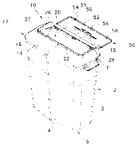
Referring to Figs. 1-7, a cover 10 that is a first embodiment of the
present invention will be described. The cover 10 is configured to be
positioned on a
medical waste disposal receptacle 2. The receptacle 2 generally includes a
body
defined by a front wall 4, a pair of side walls 3, and a rear wall 5 extending
from a
zo base 6. The walls 3, 3, 4 and 5 define a generally open end 7 opposite
the base 6.
The open end 7 defines a rim 8 about its perimeter. The rim 8 may have various
configurations. As shown in Fig. 3, the edges of the walls 3, 3, 4 and 5 are
curled over
to define the rim 8, however, a curl is not required and other configurations
may be
utilized.
The walls 3, 3, 4 and 5 are generally planar surfaces, but may have
various configurations. For example, the front wall 4 in the present
embodiment
defines a chevron shape. In the present embodiment, the rear wall 5 is a
substantially
planar surface which allows the receptacle to be positioned against a wall or
the like.
The receptacle 2 has a central axis CA extending from the base 6 to the open
end 7.
The receptacle 2 is typically positioned in use in a vertical position with
the central
axis CA extending vertically. In this typical arrangement, the open end 7
extends
CA 02538278 2006-03-01
- 5 -
along a horizontal plane. Other configurations of the receptacle 2 and other
mounting
arrangements may also be utilized.
The cover 10 generally comprises a body portion 12 and a lid portion
50. The body portion 12 includes a covering surface 14 configured to
substantially
cover and thereby close the receptacle open end 7. The covering surface 14
generally
has a configuration that complements the configuration of the receptacle rim
8. As
such, in the present embodiment, the covering surface 14 has a front portion
with a
chevron shape and a rear portion that is shaped to correspond to the planar
rear wall
5.
A flange 16 depends from at least a portion of the covering surface 14.
The flange 16 is configured to fit about the receptacle open end rim 8. The
flange 16
may be continuous about the perimeter of the receptacle rim 8 (as in the
embodiment
of cover 10 illustrated in Figs. 1-7), or may be segmented and provided at
various
positions about the receptacle rim 8. The body portion 12 is preferably
provided with
means for securing the cover 10 to the receptacle 2. In the present
embodiment,
locking tabs 17 configured to engage the receptacle rim 8 are provided at
various
locations about the flange 16, as shown in Fig. 5. Alternatively, the body
portion 12
may have a friction fit with respect to the receptacle 2, clips (not shown)
may extend
between the body portion 12 and the receptacle 2, the receptacle rim 8 may be
provided with projections which engage the flange 16, or the body portion 12
may be
provided with projections which extend through bores provided in the
receptacle rim 8.
Other securing means may also be utilized. The body portion 12 may further
include
internal ribs 13 configured to engage the receptacle 2 to further support the
cover 10
relative to the receptacle 2.
The body portion 12 has an access opening 20 through the covering
surface 14. The access opening 20 is positioned within an inlet area that is
defined by
a rear lateral edge 19, a front lateral edge 21 and opposed side edges 23 and
25
extending between the rear and front edges 19, 21. A front wall 22 is provided
along
the front lateral edge 21 and opposed side walls 26, 28 extend along the side
edges
23, 25, respectively. The lid portion 50 extends proximate to the rear edge 19
as will
be described in greater detail hereinafter.
As shown in Figs. 3 and 7, the side walls 26, 28 may extend beyond the
access opening edges 23, 25 to the location of a hinge 54 of the lid portion
50. In
CA 02538278 2006-03-01
- 6 -
use, the receptacle 2 is secured to a wall surface or the like with the lid
portion 50
pivoted to a substantially vertical or upwardly-angled position in which the
lid portion
50 rests against the wall surface. The lid portion 50 may have instructions
inscribed
on an internal surface that will be directed to a user when the lid portion 50
is in this
use position. For example, the lid portion 50 optionally includes directions
such as
"DROP SHARP HORIZONTALLY IN OPENING," other information, or other indicia for
communication to a user of the cover 10.
In this use position, the lid portion 50, the opening front wall 22 and the
opening side walls 26, 28 effectively define a funnel into the access opening
20. Any
io sharp or other device positioned within this funnel area will thereby be
directed to the
access opening 20. Referring to Fig. 1, the covering surface 14 slopes
downward from
the opening front wall 21 and the opening side walls 26, 28 to the perimeter
P. As
such, the sloped covering surface 14 is not configured to accommodate a sharp
or
other device. This configuration discourages a user from intentionally or
inadvertently
leaving a sharp or the like on the covering surface 14 which may pose a danger
to that
user or a later user.
Referring to Fig. 3, a substantially fixed tortuous path extends from the
inlet area defined by the rear lateral edge 19, the front lateral edge 21 and
the
opposed side edges 23 and 25 and through the access opening 20 to provide a
tortuous entry passage into the receptacle cavity. The tortuous entry passage
allows
for the unrestricted passage of medical instruments and/or waste past
stationary
surfaces while making hand insertion into the receptacle difficult, if not
impossible. In
the present embodiment, the tortuous path is defined by a front slide 30
extending
from the front lateral edge 21 and a rear slide 40 extending from the rear
lateral edge
19. The front and rear slides 30, 40 are formed integrally with the covering
surface
14. Preferred methods of manufacture are described in more detail hereinafter.
The front slide 30 includes a sloped front slide surface 32 terminating
along a lateral edge 34. The front slide surface 32 extends laterally between
the
opposed side walls 26, 28 and has a generally planar configuration, although
other
configurations are possible. The rear slide 40 includes a sloped rear slide
surface 42
terminating along a lateral edge 44. The rear slide surface 42 has a curved
surface
that reduces in slope toward the lateral edge 44. Other configurations are
also
possible. The rear slide surface 42 extends laterally between rear slide
surface edges
CA 02538278 2006-03-01
-7-
41 and 43 as shown in Fig. 2. Each side wall 26, 28 includes or extends to an
extending wall portion 27, 29, respectively, extending from the side wall 26,
28 to the
respective slide surface edge 41, 43. The extending wall portions 27, 29
extend
between the rear edge 19 and the front slide surface lateral edge 34, but may
extend
farther.
The extending wall portions 27, 29 retain deposited materials within the
lateral extents of the rear slide surface 42 and also provide support for the
rear slide
surface 42 of rear slide 40. A substantially rectangular lower opening is
therefore
defined by the lateral edge 44 of the rear slide surface 42 and the forward
edges of
m the extending wall portions 27, 29. This lower opening is oriented in a
plane that is
substantially vertical or at an angle to a vertical plane, as will be
described later in
greater detail. Supporting ribs 46 or the like may be provided along a rear
surface of
the rear slide 40, on or opposite rear slide surface 42, at various locations
between the
side edges 41, 43 to provide additional support.
The perimeter edge of the access opening 20 is therefore defined by the
rear lateral edge 19, the front lateral edge 34 and upper edges of the
extending wall
portions 27, 29. Thus, a substantially rectangular access opening 20 (in the
embodiment illustrated in Figs. 1-7) is oriented along a plane that is sloped
toward the
rear of the cover 10.
Medical waste introduced into the tortuous path through the inlet area
of the cover 10 follows a circuitous path into the interior of the receptacle
2. More
specifically, medical waste is deposited within the interior of the receptacle
2 after it
passes into the inlet area defined by the rear lateral edge 19, front lateral
edge 21 and
opposed side edges 23 and 25; travels through the access opening 20 defined by
the
rear lateral edge 19, the front lateral edge 34 and upper edges of the
extending wall
portions 27, 29; and passes through the lower opening defined by the lateral
edge 44
of the rear slide surface 42 and the forward edges of the extending wall
portions 27,
29.
The front slide 30 and the rear slide 40 are configured such that the
front slide surface 32 is horizontally axially spaced from the rear slide
surface 42 in
non-overlapping relation. More specifically, a plane Si parallel to the
central axis CA
and extending through the front lateral edge 34 of the front slide surface 32
is
horizontally axially spaced a distance d from a plane S3 parallel to the
central axis CA
CA 02538278 2006-03-01
- 8 -
and extending through the lateral edge 44 of the rear slide surface 42. The
distance d
is from 0 inches to approximately 1 inch, with a preferred range from greater
than
zero inches to about 7/8 inch, and a more preferred range from about 1/8 inch
to
about 5/8 inch, and a more preferred range from about 1/4 inch to about 1/2
inch.
Additionally, a plane 52 extending through the front lateral edge 34 of the
front slide
surface 32 and the lateral edge 44 of the rear slide surface 42 (i.e., the
plane of the
lower opening defined by the lateral edge 44 of the rear slide surface 42 and
the
forward edges of the extending wall portions 27, 29) is at an angle a relative
to the
plane 51. The angle a is from 0 degrees to approximately 25 degrees, with a
preferred
io range from greater than 0 degrees to about 20 degrees, and a more
preferred range
from about 2 degrees to about 15 degrees, and a more preferred range from
about 5
degrees to about 10 degrees. The distance d and the angle a are selected to
provide a
tortuous path entry passage having a desired waste clearance and a desired
user
inaccessibility.
The substantially fixed tortuous path allows a user to dispose of an item
into the receptacle 2 by dropping the item into the funnel area leading to the
access
opening 20. Gravity causes the item to pass by the front and rear slides 30,
40 and
into the receptacle 2. The user does not have to actuate the cover 10 to cause
disposal or even contact the cover 10 in any manner during disposal. The
disposed
item passes freely into the receptacle 2, however, the tortuous path reduces
or
eliminates the possibility of an individual reaching into the receptacle 2.
While the present embodiment is described with a front slide 30 and a
rear slide 40, both may not be necessary. For example, the front slide 30 may
be
eliminated while the rear slide surface 42 is extended axially in a forward
direction.
With the front slide 30 eliminated, the plane Si would extend through the
opening
front edge 21. If so modified, the spatial relationship between the planes Si
and S3
and the angular relationship between planes 52 and Si provided in the cover 10
would
still be maintained to provide a desired tortuous path.
Additionally, while the present embodiment is described with the rear
slide surface 42 having a larger axial length than the front slide surface 32,
such
configuration can be reversed. For example, the front slide surface 32 may be
configured with a larger axial length and extending at a steeper angle such
that the
CA 02538278 2006-03-01
- 9 -
front lateral edge 34 of the front slide surface 32 is lower than the lateral
edge 44 of
the rear slide surface 42. Other configurations may also be utilized.
To close the access opening 20 once the receptacle is filled to a desired
level, the cover 10 includes a lid portion 50 configured to cover and close
the inlet
area and access opening 20. In the present embodiment, the lid portion 50 is
integrally hinged to the body portion 12 along a rear edge 15 of the outer
perimeter P
of the body portion 12. The outer perimeter P is defined by the outer extent
of the
covering surface 14 and the flange 16. The perimeter P may be defined by both
the
covering surface 14 and the flange 16 if, for example, the flange 16 extends
radially
io outward of the covering surface 14 along a portion of the perimeter, but
is inward of
the covering surface 14 along other portions of the perimeter. At the
locations where
the flange 16 is outward, the flange 16 will define that portion of the
perimeter P and
at locations where the covering surface 14 is outward, the covering surface 14
will
define that portion of the perimeter P.
The lid portion 50 includes a lid surface 52 configured to complement
the shape of the inlet area and/or the access opening 20. In the present
embodiment,
the lid surface 52 has a substantially rectangular configuration, but other
configurations are also possible. An integral hinge 54 (e.g., a living hinge)
extends
between the lid surface 52 and the rear perimeter edge 15 of the body portion
12.
The hinge 54 of the present embodiment extends substantially along the entire
length
of the lid surface 52, however, the hinge 54 may be formed as one or more
segments
that extend less than the length of the lid surface 52. As illustrated in Fig.
5, the
hinge 54 is optionally formed by providing a section of reduced material
thickness.
Such reduced thickness provides the hinge 54 with greater flexibility than the
neighboring lid portion 50 or cover portion 10. The hinge 54 therefore has
sufficient
flexibility to allow the lid portion 50 to be pivoted from the open position
shown in Fig.
3 to the closed position shown in Fig. 5, to be described in greater detail
later.
To lock the lid portion 50 in the closed position, the lid portion 50
includes one or more locking tabs 56 extending from the lid surface 52. A
locking bore
36 corresponding to each locking tab 56 is provided adjacent the opening front
edge
21 (Fig. 4). In the present embodiment, the locking bores 36 are provided
through
the front slide surface 32 and each locking bore 36 defines a locking shoulder
38 below
the front wall 22, as shown in Fig. 4. To close the inlet area and access
opening 20,
CA 02538278 2006-03-01
- 10 -
the lid surface 52 is pivoted about the hinge 54 until each locking tab 56
engages a
respective locking shoulder 38, as shown in Fig. 7. The engagement of the
locking
tabs 56 with the locking shoulders 38 preferably permanently locks the lid
portion 50
in the closed position, prevents unauthorized opening of the lid portion 50,
and / or
inhibits unintended opening of the lid portion 50. Each locking tab 56
preferably has a
support rib 55 having a width equal to the width of the locking bore 36 to
prevent
prying of the locking tabs 56 from the locking bores 36 (see Figs. 1-3 and 7).
Having generally described the components of the cover 10 and the
operation thereof, a method of manufacturing the cover 10 that is a first
embodiment
of the inventive method will be described with reference to Figs. 3, 5 and 8-
11. The
first embodiment of the inventive method utilizes a mold assembly 300
including first
and second mold portions 302, 304 that are linearly moveable relative to each
other in
a direction parallel to the mold axis MA. The mold assembly 300 is configured
for use
in an injection molding process in which plastic material is injected into a
cavity
is defined by mold portions 302, 304 to form the cover 10. In use, the mold
portions
302, 304 are moved with respect to one another along the mold axis MA between
an
open position in which the mold portions are spaced from one another (e.g.,
for
removal for a completed cover 10) and a closed position in which the mold
portions
contact one another to define the cavity.
The mold portions 302 and 304 have a control assembly for controlling
the alignment and movement of the mold portions 302 and 304 relative to one
another. For example, one mold portion 304 may be provided with posts 308 that
are
received in corresponding bores 306 in the other mold portion 302 to align and
control
linear motion of the mold portions 302 and 304. Other assemblies may also be
utilized.
The mold assembly 300 has one or more injection ports 330 or the like
configured to dispose moldable material in cavity portions 318, 320, 322, 324,
326
formed between the mold portions 302 and 304. The mold portions 302 and 304
and
cavity portions 318, 320, 322, 324, 326 are configured such that all of the
components of the cover 10 may be formed as a unitary structure while allowing
simple linear separation of the mold portions 302 and 304 in a direction
parallel to the
mold axis MA, as indicated by arrows A in Fig. 11. In other words, all of the
surfaces
of the mold cavity forming cover 10 are provided, according to one exemplary
aspect
CA 02538278 2006-03-01
- 11 -
of this invention, by two mold portions movable along a common axis. Thus,
simplified and cost effective mold tooling and processes are optionally
employed,
thereby reducing the effort and cost associated with the manufacture of the
cover 10.
Known mold assemblies, in contradistinction, have required additional mold
components, for example, cross sliding components to make complex, unitary
structures.
Referring to Figs. 8-11, both mold portions 302, 304 include male and
female mold surfaces 310, 311, 312, 313, 315, 317, 319, 321, 323, 325, 327,
329,
331, 333, 335 configured and positioned to define the cavity portions 318,
320, 322,
io 324, 326 when the mold portions 302 and 304 are positioned relative to
one another.
For example, a cavity portion 324 configured to form the rear slide 40 of the
cover 10
is defined by mold surfaces 311, 312 and 313 while cavity portion 322
configured to
form the front slide 30 of the cover 10 is defined by mold surfaces 310, 315
and 317.
As shown in Figs. 10 and 11, the mold surfaces 310 and 312 mate along
the plane S2, which is the plane that extends through the front lateral edge
34 of the
front slide surface 32 and the lateral edge 44 of the rear slide surface 42 of
the cover
10 (i.e., the plane of the lower opening defined by the lateral edge 44 of the
rear slide
surface 42 and the forward edges of the extending wall portions 27, 29). The
plane
Si (the plane parallel to the central axis CA and extending through the front
lateral
zo edge 34 of the front slide surface 32 of the cover 10) is configured to
be substantially
parallel to the mold axis MA. The angle a of the mating plane S2 relative to
the plane
Si allows the mold surfaces 310 and 312 to adequately seal between the two
cavities
322 and 324. Additionally, the angle a of the mating plane S2 allows the two
mold
portions 302 and 304 to be moved apart in a direction parallel to the mold
axis MA, as
indicated by arrows A, without interfering with either of the molded slide
surfaces 32
or 42 that are formed in the cavity portions 322 and 324, respectively. As
indicated
previously, the angle a according to one embodiment is between 0 degrees and
approximately 20 degrees, with a preferred range from about 2 degrees to about
15
degrees, and a more preferred range from about 5 degrees to about 10 degrees.
Additional mold surfaces 325 may be provided adjacent the surface 313
to assist in forming the locking tabs 17 along the rear portion of the rim 16.
As
illustrated in Fig. 5, the mold surfaces 325 leave apertures 18 through the
covering
surface 14; however, the apertures 18 are sufficiently small that they do not
allow
CA 02538278 2006-03-01
- 12 -
access within the cover 10 and are also covered by the lid portion 50 when the
lid
portion 50 is closed as illustrated in Fig. 7. Similarly, mold surfaces 335
may be
provided adjacent mold surface 317 to define the locking bores 36 illustrated
in Fig. 4.
The mold surfaces 335 cooperate with the mold surface 319 to define the
locking
shoulders 38.
Mold surface 319 also cooperates with mold surfaces 321 and 323 to
define cavity portion 320 configured to form the body portion 12. Mold
surfaces 327
and 329 cooperate to define cavity portion 326 configured to form the lid
surface 52.
Mold surfaces 327 and 329 further cooperate with mold surface 325 to define
cavity
to portion 318 configured to form the hinge 54 between the lid surface 52
and the body
portion 12. The mold surface 329 is preferably configured to form the flange
16 with
an inward draft angle, as indicated in Fig. 5 by the angle 0 between planes E
and F.
The inward draft angle assists in defining the hinge cavity portion 318 and
the
separation of the mold portions 302 and 304. Mold surfaces 327, 331 and 333
is cooperate to define a cavity portions configured to form the locking
tabs 56.
As illustrated in Fig. 11, the mold surfaces are preferably configured
such that the cavity portion 326 that forms the lid portion 50 is at an
approximate
right angle with respect to the mold axis MA to facilitate separation of the
mold
portions 302 and 304 in the direction of arrows A. However, other angles may
also be
20 utilized.
To form the integral cover 10, moldable material is supplied to the
cavity portions, for example, through injection ports 330. The mold portions
302 are
thereafter separated in the direction of arrows A in Fig. 11 and the integral
cover 10 is
removed. The cover 10 is substantially ready for use and does not require any
25 substantial secondary operations to assemble the cover 10.
Referring to Figs. 12-14, a cover 110 that is alternate embodiment of
the present invention will be described. The cover 110 is similar to cover 10
in that it
has a one-piece construction that is capable of being formed using a cost
effective
molding process. As will be describe in detail below, however, the cover 110
differs
30 from cover 10 in the manner in which the lid is coupled to the body
portion and in
other ways.
CA 02538278 2006-03-01
- 13 -
The cover 110 includes a body portion 112 and a lid portion 150. The
body portion 112 includes a covering surface 114 configured to substantially
cover and
thereby close a receptacle open end 7. The covering surface 114 generally has
a
configuration that complements the configuration of the receptacle rim 8. In
the
present embodiment, the covering surface 114 has a chevron shape in both the
front
and rear portions.
A flange 116 depends from at least a portion of the covering surface
114. The body portion 112 of cover 110 is preferably provided with means for
securing the cover 110 to a receptacle 2. In the present embodiment, locking
tabs
117 configured to engage the receptacle rim 8 are provided at various
locations about
the flange 116, as shown in Fig. 14. Other securing means may also be
utilized.
The body portion 112 has an access opening 120 through the covering
surface 114. The access opening 120 is defined by a rear lateral edge 119, a
front
lateral edge 121 and opposed side edges 123 and 125 extending between the rear
and
front edges 119, 121. Referring to Fig. 14, a substantially fixed tortuous
path extends
from the access opening 120 to provide a tortuous entry passage into the
receptacle
cavity from the access opening 120 which allows for the unrestricted passage
of
medical instruments and/or waste past stationary surfaces while making hand
insertion into the receptacle difficult, if not impossible. In the present
embodiment,
the tortuous path is defined by a rear slide 130 extending from the opening
rear
lateral edge 119 and a front slide 140 extending from the opening front
lateral edge
121. The rear and front slides 130, 140 are formed integrally with the
covering
surface 114.
The rear slide 130 includes a sloped rear slide surface 132 terminating
along a lateral edge 134. The rear slide surface 132 extends laterally between
opposed side walls 127 and has a generally planar configuration, although
other
configurations are possible. The front slide 140 includes a stepped front
slide surface
terminating along a lateral edge 144. The stepped slide surface includes a
first sloped
portion 142 followed by a substantially horizontal step 146 followed by a
second
sloped portion 148 that terminates at the lateral edge 144. The first and
second slide
surfaces 142 and 148 are substantially planar surfaces, but other
configurations are
also possible.
CA 02538278 2006-03-01
- 14 -
The perimeter edge of the access opening 120 is therefore defined by
the rear lateral edge 119, the front lateral edge 121 and upper edges of the
side walls
127. Thus, a substantially rectangular access opening 120 (in the embodiment
illustrated in Figs. 12-14) is oriented along a plane that is substantially
horizontal but
that may be sloped such as toward the rear of the cover 110.
The horizontal step 146 of the front slide 140 includes a plurality of
locking bores 136 configured to receive locking tabs 156 on the lid portion
150 as will
be described hereinafter. The front slide extends laterally between side walls
127.
The rear and front slides 130, 140 and the side walls 127 effectively define a
funnel-
lo shaped path into the receptacle. A substantially rectangular lower
opening is therefore
defined by the lateral edge 144 of the front slide surface 142 and the lower
edges of
the side walls 127. This lower opening is oriented in a plane that is
substantially
vertical or at an angle to a vertical plane, as will be described later in
greater detail.
Medical waste introduced into the tortuous path through the inlet area
is of the cover 110 follows a circuitous path into the interior of the
receptacle 2. More
specifically, medical waste is deposited within the interior of the receptacle
2 after it
passes into the inlet area; travels through the access opening 120 defined by
the rear
lateral edge 119, the front lateral edge 121 and upper edges of the side walls
127;
and passes through the lower opening defined by the lateral edge 144 of the
front
20 slide surface 142 and the lower edges of the side walls 127.
The rear slide 130 and the front slide 140 are configured such that the
rear slide surface 132 is axially spaced from the front second slide surface
148 in non-
overlapping relation. A plane Si parallel to the central axis CA and extending
through
the rear lateral edge 134 is axially spaced a distance d from a plane S3
parallel to the
25 central axis CA and extending through the front lateral edge 144. The
distance d is
from 0 inches to approximately 1 inch, with a preferred range from greater
than zero
inches to about 7/8 inch, and a more preferred range from about 1/8 inch to
about 5/8
inch, and a more preferred range from about 1/4 inch to about 1/2 inch.
Additionally,
a plane S2 extending through the rear lateral edge 134 and the front lateral
edge 144
30 is at an angle a relative to the plane Si. The angle a is from 0 degrees
to
approximately 25 degrees, with a preferred range from greater than 0 degrees
to
about 20 degrees, and a more preferred range from about 2 degrees to about 15
degrees, and a more preferred range from about 5 degrees to about 10 degrees.
The
CA 02538278 2006-03-01
- 15 -
distance d and the angle a are selected to provide a tortuous path entry
passage
having a desired waste clearance and a desired user inaccessibility.
To close the access opening 120 once the receptacle is filled to a desired
level, the cover 110 includes a lid portion 150 configured to cover and close
the access
opening 120. In the present embodiment, the lid portion 150 is integrally
hinged to
the body portion 112 along the outer perimeter P of the body portion 112 via
straps
153. The lid portion 150 includes a lid surface 152 configured to complement
the
shape of the access opening 120. In the present embodiment, the lid surface
152 has
a rectangular configuration, but other configurations are also possible.
io Each strap 153 extends between the lid surface 152 and a
respective
integral hinge 154 extending along the perimeter P of the body portion 112. To
lock
the lid portion 150 in the closed position, the lid portion 150 includes one
or more
locking tabs 156 extending from the lid surface 152. To close the access
opening 120,
the lid surface 152 is pivoted about the hinges 154 until each locking tab 156
engages
in a respective locking bore 136. As illustrated in phantom in Fig. 13, the
locking
bores 136' may alternatively be provided along the covering surface 114.
The cover 110 is configured such that it can be manufactured utilizing
the method described above with respect to cover 10. The mold surfaces will be
arranged to provide cavity portions corresponding to the various components of
cover
110. Again, the components are configured such that the mold portions may be
linearly separated to remove the integrally formed cover 110.
Referring to Figs. 15-17, a cover 210 that is alternate embodiment of
the present invention will be described. The cover 210 is similar to cover 10
and cover
110 in that it has a one-piece construction that is capable of being formed
using a cost
effective molding process. As will be described in detail below, however, the
cover
210 differs from cover 10 and cover 110 in the manner in which the lid is
coupled to
the body portion and in other ways.
The cover 210 includes a body portion 212 and a lid portion 250. The
body portion 212 includes a covering surface 214 configured to substantially
cover and
thereby close a receptacle open end 7. The covering surface 214 has a
substantially
domed configuration, thereby providing a more pronounced profile as compared
to
that of covers 10 and 110. Such a profile is optionally provided in order to
maximize
CA 02538278 2006-03-01
- 16 -
the capacity of the receptacle 2, to provide steeper slopes at the front and
side
portions of the cover, and/or to permit a deeper extension of the surfaces
defining the
covers tortuous path.
The covering surface 214 generally has a configuration that
complements the configuration of the receptacle rim 8. In the present
embodiment,
the covering surface 214 has a chevron shape in both the front and rear
portions. The
covering surface 214 of the present embodiment has a relatively steep slope
such that
the body portion 212 is deeper than that of the previous embodiments, as
mentioned
previously.
A flange 216 depends from at least a portion of the covering surface
214. The body portion 212 is preferably provided with means for securing the
cover
210 to a receptacle 2, for example, locking tabs or the like configured to
engage the
receptacle rim 8. Other securing means may also be utilized.
The body portion 212 has an access opening 220 through the covering
surface 214. The access opening 220 is defined by a rear lateral edge 219, a
front
lateral edge 221 and opposed side edges 223 and 225 extending between the rear
and
front edges 219, 221. A front wall 222 is provided along the opening front
lateral
edge 221.
Referring to Fig. 15, a substantially fixed tortuous path extends from the
access opening 220 to provide a tortuous entry passage into the receptacle
cavity from
the access opening 220 which allows for the unrestricted passage of medical
instruments and/or waste past stationary surfaces while making hand insertion
into
the receptacle difficult, if not impossible. In the present embodiment, the
tortuous
path is defined by a rear slide 230 extending from the opening rear lateral
edge 219
and a front slide 240 extending from the opening front lateral edge 221. The
rear and
front slides 230, 240 are formed integrally with the covering surface 214.
The rear slide 230 includes a sloped rear slide surface 232 terminating
along a lateral edge 234. The front slide 240 includes a front slide surface
242
terminating along a lateral edge 244. The front slide surface 242 depends a
distance
Y from the covering surface 214. The distance Y is preferably less than the
depth D of
the body portion 212 in order to maintain the slide surface 242 above the
interior of
CA 02538278 2006-03-01
- 17 -
the receptacle 2. The rear and front slide surfaces 232 and 242 are
substantially
planar surfaces, but other configurations are also possible.
The rear slide 230 and the front slide 240 are configured such that the
rear slide surface 232 is axially spaced from the front slide surface 242 in
non-
overlapping relation. A plane Si parallel to the central axis CA and extending
through
the rear lateral edge 234 is axially spaced a distance d from a plane S3
parallel to the
central axis CA and extending through the front lateral edge 244. The distance
d is
from 0 inches to approximately 1 inch, with a preferred range from greater
than zero
inches to about 7/8 inch, and a more preferred range from about 1/8 inch to
about 5/8
io inch, and a more preferred range from about 1/4 inch to about 1/2 inch.
Additionally,
a plane S2 extending through the rear lateral edge 234 and the front lateral
edge 244
is at an angle a relative to the plane Si. The angle a is from 0 degrees to
approximately 25 degrees, with a preferred range from greater than 0 degrees
to
about 20 degrees, and a more preferred range from about 2 degrees to about 15
is degrees, and a more preferred range from about 5 degrees to about 10
degrees. The
distance d and the angle a are selected to provide a tortuous path entry
passage
having a desired waste clearance and a desired user inaccessibility.
The perimeter edge of the access opening 220 is therefore defined by
the rear lateral edge 219, the front lateral edge 221 and the upper edge
portions of
zo the opposed side edges 223 and 225. Thus, a substantially rectangular
access
opening 220 (in the embodiment illustrated in Figs. 15-17) is oriented along a
plane
that is substantially horizontal but that may be sloped such as toward the
rear of the
cover 210. A substantially rectangular lower opening is defined by the lateral
edge
244 of the front slide surface 242 and the lower edges portions of the opposed
side
25 edges 223 and 225. This lower opening is oriented in a plane that is
substantially
vertical or at an angle to a vertical plane, as will be described later in
greater detail.
Medical waste introduced into the tortuous path through the inlet area
of the cover 210 follows a circuitous path into the interior of the receptacle
2. More
specifically, medical waste is deposited within the interior of the receptacle
2 after it
30 passes into the inlet area; travels through the access opening 220
defined by the rear
lateral edge 219, the front lateral edge 221 and upper edge portions of the
opposed
side edges 223 and 225; and passes through the lower opening defined by the
lateral
CA 02538278 2006-03-01
- 18 -
edge 244 of the front slide surface 242 and the lower edges portions of the
opposed
side edges 223 and 225.
To close the access opening 220 once the receptacle is filled to a desired
level, the cover 210 includes a lid portion 250 configured to cover and close
the access
opening 220. In the present embodiment, the lid portion 250 is integrally
hinged to
the body portion 212 along the outer perimeter P of the body portion 212 via
straps
253. The lid portion 250 includes a lid surface 252 configured to complement
the
shape of the access opening 220. Each strap 253 extends between the lid
surface 252
and a respective integral hinge 254 extending along the perimeter P of the
body
portion 212.
Due to the deeper nature of the body portion 212 (as compared to body
portions 12 and 112 of other cover embodiments), the straps 253 have an
extended
length with a intermediate locking tab 255 and a secondary hinge 257. To move
the
lid surface 252 to an operable position, the straps 253 are pivoted about the
hinges
254 and the intermediate locking tabs 255 are inserted into intermediate
locking bores
235 in the covering surface 214. The straps 253 have a length L that is
approximately
equal to the depth D of the body portion 212 such that when the locking tabs
255 are
locked in the locking bores 235, the hinges 257 are adjacent the top of the
body
portion 212. As such, to lock the lid portion 250 in the closed position, the
lid surface
252 is pivoted about the hinges 257 until each locking tab 256 engages in a
respective
locking bore 236.
The cover 210 is configured such that it can be manufactured utilizing
the method described above with respect to cover 10. The mold surfaces will be
arranged to provide cavity portions corresponding to the various components of
cover
210. Fig. 15 illustrates bores 218 that may be provided to mold internal
components,
for example, internal locking tabs (not shown). Again, the components are
configured
such that the mold portions may be linearly separated to remove the integrally
formed
cover 210.
Although the invention is illustrated and described herein with reference
to specific embodiments, the invention is not intended to be limited to the
details
shown. Rather, various modifications may be made in the details within the
scope and
range of equivalents of the claims and without departing from the invention.