Note: Descriptions are shown in the official language in which they were submitted.
CA 02538472 2006-03-06
1
Container for food products
Cross-Reference to Related Applications
The present application claims priority from Australian Provisional Patent
2005901054, and Australian Provisional Patent 2005901408 filed on 7 March
2005, 22
March 2005, the contents of which are incorporated herein by reference.
Field of the Invention
This invention relates to a food container particularly for forming a party
platter
or the like.
Background of the Invention
Party platters are sold by supermarkets, delicatessens and the like. A typical
party platter comprises a circular or oval platter or plate, typically with a
circular
container holding a dip of some sort in the centre of the platter. Around the
outside of
the dip a series of stacks of different food products, typically small goods
such as sliced
salami, sausages, sliced ham, olives, gherkins, cubed cheeses or the like, are
arranged.
Generally speaking the food stacks are shaped like a sector of a circle, in
plan view.
Although, many supermarkets provide party platters, often the provision of
such
platters is not profitable or cost effective. That is because it is an
expensive and labour
intensive process to create the platters, as they are typically assembled by
hand. First,
any food products which are not already diced or sliced into bite-sized pieces
require
slicing in the case of hams and salamis and the like, or cubing, in the case
of cheeses or
the like. Next the food products have to be weighed and then stacked in
generally
triangular piles, and subsequently the entire platter has to be wrapped in
cling-film or
the like.
Aside from the labour intensive manufacture of such platters, the fact that
they
do take time to assemble means that they have to be ordered by customers in
advance,
typically from a brochure which a customer looks up and from which a
particular
platter is ordered and subsequently assembled. Such platters have a short
shelf life and
cannot therefore be displayed for impulse purchase by customers.
One additional problem is cross-contamination of the different foods on the
platter. This is a particular problem if the platter includes both wet foods
such as
olives, gherkins or the like, as well as dry foods, such as crackers. Liquids
from the
wet foods often soften the dry foods such as crackers and limit the length of
time for
which the platter may be prepared prior to use.
CA 02538472 2006-03-06
2
The present invention seeks to provide improved packaging means for forming a
party platters, or the like, which may overcome some of the disadvantages of
the prior
art.
Any discussion of documents, acts, materials, devices, articles or the like
which
has been included in the present specification is solely for the purpose of
providing a
context for the present invention. It is not to be taken as an admission that
any or all of
these matters form part of the prior art base or were common general knowledge
in the
field relevant to the present invention as it existed before the priority date
of each claim
of this application.
Throughout this specification the word "comprise", or variations such as
"comprises" or "comprising", will be understood to imply the inclusion of a
stated
element, integer or step, or group of elements, integers or steps, but not the
exclusion of
any other element, integer or step, or group of elements, integers or steps.
Summary of the Invention
In a first aspect the present invention provides a container for food products
formed from a sheet of material having a base and a top, at least two opposed
converging side walls, and a first end wall, and wherein a peripheral flange
extends
around the top of the container, and wherein one or more male connecting means
in the
form of depending lugs are defined in the flange of one side wall and female
connecting means are defined in the flange of the other opposite side wall
such that two
such containers can be attached or interlocked to one another along their
sides, to form
an assembly of such containers.
In use the containers will be filled with food products and sealed. The
depending lugs allow the containers to be run and sealed on conventional
commercial
sealing apparatus. Platters can be assembled by conjoining multiple
containers. By
providing a series of discrete sealed pockets, the different foods for the
platter may be
kept separate. This.allows both wet and dry foods to be sold in the same
platter.
The containers may be gas flushed prior to sealing. This improves the shelf
life
of the food products. Further this enables sealed containers to be displayed
to
customers for impulse purchase, which is not currently possible with existing
methods
for preparing platters.
Typically, in the platter, different pockets will contain different food
products
from other pockets, although some products may be contained in more than one
pocket.
It is a preferred feature that at least some embodiments of the container are
microwaveable. In this way a container of, say sausage rolls, can be heated in
a
CA 02538472 2006-03-06
3
microwave and conjoined with other containers of food products which are
typically
eaten cold. It then become possible to assemble platters which provide both
hot and
cold foods which is not currently possible.
It is preferred that the platter defines a central aperture for supporting a
container of dip, sauce or the like.
The wall of the central aperture may be higher than the outer edge wall of the
platter so that the container slopes upwards from its outer edge towards its
centre.
The base of one or more of the pockets may define a recess which may be
reversed to define a protrusion thereby raising the level of any food product
in the
pocket. This allows the pockets to be sealed allowing head space for the food
product
and at the same time by reversing the recess, raises the level of the food
product in the
pocket allowing easier access.
In one version the female connecting means comprises lugs having a diameter
slightly greater than a diameter of the male depending lugs.
In another version, the female connecting means comprises apertures having a
diameter slightly greater than a diameter of the male depending lugs.
The converging side walls may be linked by a second end wall which is shorter
than the first end wall or may meet at a corner.
It is advantageous that the longer end wall is lower in height than the second
end
wall or corner, so that the sides of the container extend generally upwards
from the first
wall to the second end wall or corner.
In a preferred embodiment the angle subtended by the converging side walls and
divided into 360° produces an integer so that when sufficient
containers are joined side
wall to side wall the resultant combination of units is generally circular.
Most preferably the angle which is subtended between the side walls of the
container is 45° or 60° or 90°.
In one embodiment the second end wall is curved as is the first end wall.
The curved walls may be arcuate and concentric or non-concentric.
In another embodiment, the second end wall is straight.
The base of the container may define a recess which may be reversed to define
a
protrusion thereby raising the level of any food product in the container.
Because of the shape of the container, as the container is emptied onto the
platter, the food product will be deposited in a pile/stack of the correct
configuration for
the platter.
CA 02538472 2006-03-06
4
Brief Description of the Drawings
Specific examples of the present invention will now be described, by way of
example only, with reference to the accompanying drawings in which:
Figure 1 is an perspective view from above of a first embodiment of a
container
for food products;
Figure 2 is an underneath plan view of the container of Figure 1;
Figure 3 is a sectional view on lines III-III of the container of Figure 2;
Figure 4 is a perspective view from below of the container of Figure 1;
Figure 5 is an end view of the container of Figure 2;
Figure 6 is an pictorial view of a second embodiment of a container unit for
food
products;
Figure 7 is a top view of the container shown in Figure 5;
Figure 8 is a section on lines VIII-VIII of Figure 7;
Figure 9 is a top view of six units such as those shown in Figure 5
interlocked
1 S together to form a cylindrical platter each containing multiple discrete
pieces of a
particular food product;
Figure 10 shows a die pattern for forming a plurality of containers as shown
in
Figure 6 by a thermoforming process;
Figure 11 illustrates the interlocking of flanges of the container of Figure
6;
Figure 12 is a pictorial view of a four containers according to third
embodiment
of the invention, the containers being similar but not identical to the first
embodiment
shown Figure 1, partially assembled into a platter.
Figure 13 is a pictorial view of a platter assembled from six containers
similar to
those shown in Figure 6;
Figure 14a is an isometric view showing an apparatus for filling and sealing
preformed containers such as those shown in Figure 13;
Figure 14b is a schematic view illustrating a thermoform rollstock apparatus
for
making and sealing containers embodying the present invention;
Figure 15 is a plan view of a further embodiment of a container for food
products having a straight outer edge;
Figure 16 is a plan view of six such containers interconnected to form a
platter;
Figure 17 is a plan view of a further embodiment of a container unit for food
products;
Figure 18 is a section on lines XVIII-XVIII of Figure 17;
Figure 19 is a top view of six units such as those shown in Figure 17
interlocked
together to form a cylindrical platter;
CA 02538472 2006-03-06
Figure 20 is a plan view of a yet further embodiment of a container unit for
food
products;
Figure 21 is a section on lines XXI-XXI of Figure 20;
Figure 22 is a top view of six units such as those shown in Figure 21
interlocked
5 together to form a hexagonal platter;
Figure 23 is a plan view of a yet further embodiment of a container unit for
food
products;
Figure 24 is a section on lines XXIV-XXIV of Figure 24;
Figure 25 is a top view of six units such as those shown in Figure 24
interlocked
together to form a petaloid or flower shaped platter;
Detailed Description of Preferred Embodiment
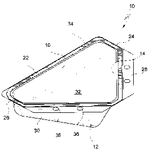
Referring to the drawings, Figures 1 to 5 shows a first container 10 for
containing food products. In plan view the container is generally triangular
but with
rounded corners where the two side walls 12, 14 and the end wall 16 of the
container
meet.
At the top 18 of the container, an external flange 20 is defined which extends
in
a plane around the perimeter of the top of the container. The width of that
portion 22 of
the flange 20 which extends along the top of the rear wall 16 is typically of
the order of
6-lOmm. Two relatively shorter flange portions 24, 26 are located above the
rounded
corners where the side walls 12 and 14 meet the end wall 16 and extend at
90° to the
flange portion 22. Those portions 28 and 30 of the flange 20 which extend
above the
side walls 14 and 12 respectively are relatively wider than flange portions 22
to 26,
and are typically of the order of about 20mm wide.
The base 32 of the container is generally triangular in shape and is oriented
at
and angle a of about 25° relative to the plane of the top 18/flange 20
of the container
(best seen in Figure 3). The side walls 12 and 14 meet at and angle of
90° and with
reference to Figure 3, the join between the two side walls is oriented at an
angle ~3 of
about 28°. The function of the particular and unusual shape of the
container is
explained in more detail below.
A sealing strip 34 of heat activated adhesive or the like which assists in the
bonding of a sealing web to the container, extends around the flange which may
be
used to seal a cover over the container, after the container has been filled.
Alternatively
the sealing web may be heat sealed to the container. The strip 34 extends
around the
perimeter in an unbroken loop. Means for interlocking a container 20 to an
adjacent
container are provided in the wider flange portions 28 and 30. Specifically,
two
CA 02538472 2006-03-06
6
depending cylindrical lugs 34 depend from flange 28. These are formed by
deformations in the sheet of plastic from which the flange and container body
is
moulded. Two circular holes 36 of a diameter equal to or marginally less than
the
outside diameter of are defined in the other flange 30.
Up to four containers 10 can be interlocked together. Flange 28 may be
interlocked to flange 30 of an adjacent identical container by placing flange
28 over
flange 30 of the adjacent container aligning the lugs 34 over the holes 36 and
pressing
the flanges together. A third container may have its flange 28 interlocked to
the free
flange 30 of the two joined containers in the same way, and a fourth may have
its
flanges 28 and 30 connected to the free flanges 28 and 30 of the three
conjoined
containers to define a ring of four conjoined containers.
The containers 10 are intended to be sold pre-filled each typically containing
multiple discrete pieces of a particular food product and sealed with a
sealing sheet of
plastic, aluminium or other suitable material bonded to the flange 22 to
maintain
product integrity and freshness. Various options exist for manufacturing the
sealed
containers. In one process the containers are pre-moulded, either at a food
processing
factory or elsewhere and transported to the factory. The pre-moulded
containers may
be filled automatically, or by hand, with a food product which is pre-sliced
or diced to
the appropriate sized pieces and sealed. The same factory may fill and seal
similar
containers with a multitude of different food products, in batches. A machine
for
performing this function is described in more detail below with reference to
Figure 14.
At a supermarket, delicatessen or the like, a platter may be assembled by
interlocking combinations of different containers each typically containing a
different
food product. Different combinations of food product can be provided. The
resultant
platters may be provided to customers still sealed and the customer can open
the seals
on the containers place an inverted plate over the top of the platter and
invert the plate
and containers to transfer the contents to the plate. Because of the shape of
the
containers 10, the pre-sliced or pre-diced foods are constrained in the
container in the
correct shape to form a stack for a platter. Alternatively, these steps may
take place at
the supermarket or delicatessen and the platter may be provided to the
customer readily
opened on a plate. In a variation, the containers 10 of food products may
simply be
sold as they are for customers to assemble their own platters at home.
Customers can
then make up their own platters as they wish, with combinations of foods
selected by
themselves. This has the added advantages of the sealed containers providing
improved hygiene and reduced likelihood of contamination of the contents and
also
being easier to carry than a platter. Product separation, inherent in the
design, also
CA 02538472 2006-03-06
prevents cross-contamination of the individual platter constituents (c.c. meat
or cheese
with liquid from olives or gherkins) which reduces the use by time of the
planer, thus
allowing earlier assembly of the planer and enhancing the quality of the whole
platter.
Figure 14a shows a naachiae 144 for filling pre-formed cor~ainexs of the type
shoran in 1~ iguxes 1 to 5, although it is to be anted that the tablC 102 of
the machiste 100
is set up to receive pre-moulded containers 114A of a difFercnt shape to
Figure 1 to 5
which are described in more detail below with reference to Figure 13, six of
which
interlock to form a platter, although the prizLCipies behitad the falling and
sealing of the
containers remain the same. The machine includes rivo substantially identics!
jwctaposed tables I02A, B. Each cable 142A, B defines two apertures 104 far
receiving
containers 110A. A recess 106 extending around the aperture supports tk~.~
flange of the
containers The containers are placed in the aparrures on the table and $Iled,
or may be
loaded onto the table pre-filled. 7 he upper part 108 of the apparatus is then
moved into
position above the container and the container is ~tushed with gas to create
art
13 appropriate atmosphere for storage of the product, depending en the type of
product,
and the Container is than sealed closed with a plastic elm, While the
containers in ono
of the tables 102A are bei~ sealed, the other table 102B sealed containers may
be
unloaded from the other table and loaded with fresh containers I l0a for
sealing after
those ors table 102A have been sealed; to make the ~ufaccuring process quicker
and
more efficient,
Alternatively, as illustrated in 1~igure 14b, particularly for large scale
manufacture, the containers may be formed from plastic sheet/tilm,
automatically filled
and scaled ire, one process on a thermoform rollstock machine. In such a
thermoforming
process packaging material 200 for the base container 10 (theznzo forming elm)
is
unwound frorx~ a reel 2I0 , heated in a forming dye 224 in which several
containers are
formed simultaneously. Typically the material used to form the container is a
web of
350 micron P'VC with a 51 micron )<)<.bVl' (linear low density polyethylene)
coating.
The formed containers are then lorded manually ar automatically. ,4n upper web
of
packaging material then covers the i'xlled packets. The upper web 210 forming
the seal
comprise$ a web of 15 micron biaxially oriented nylon a layer of 38 micron
petiable
ca-extruded seaIarzt so that the total thickness of the web is 51 micron. Both
Web
ptnducts are available from Scaled Air Corporation of NeW rexsey, USA under
their
"Cryovac" registered trade mark. 'fhe formed containers IO are then fillmd
either
automatically or mar~.vally at 230. The upper web 240 of material then covers
the fitted
containers as they are transferred to o sealing die 250. Air is then evacuated
from the
cozttainer and a protective gas is added, if required. 'tee package is thexa
sealtd by the
CA 02538472 2006-03-06
application of heat and pressure. the web of packs is then cut using a cutting
means
260 to separate the individual packs which arc then packed grad sold.
Typically the
containers will be formed and assembled in batches, say a batch of meat stinks
first,
then say sliced salami, then same other food product, and so on.
5 The individual paelrs can be spe~cally desigied for the particular product
applications, with a vacuum modified atmosphere, with a rigid or flexible film
or any
aluminium material based combination, with opeztlrtg arid re-closure facility,
coding ox
the like to suit the particular product.
Figures 6 to $ show a second embodiment of a containex 110. The container has
a generally flax base 111. With re~c~resrce to Figure 7, the container de~nes
a relatively
longer arcuate outer wall 112 and a relatively shorter, but eoncensric,
arcuate firmer wall
114. The radius of the outer wall is 200mm and that of the inner wall is 55mrn
although these dimensions could be varied. The ends of the arcuate wills are
cozmected by two radially extending saaight side walls 116 and 118. The angle
7
1 S subtended by the two side walls is 60°.
rn the specific example shown, the outer vv~all 114 has a height h~ of 70
millimetres, axul t?~e inner wall a height h2 of 20 millimetres from the base
111 to its top
120. Also as cazx be best seen in Figure 8, the outer wall 112, is extends way
grom the
container at au a~ngte of about I 10 to 120° rather than being
perpendicular to the base
20 1I1.
An external flange 122, extends around the pexirneter of the top 120 of the
container. As shown in Figure 7, the plane flange is oriented in a plape at an
angle of
about 30-40o to the plane of the base 111. The part 122A of the flange
extending along
the top of side wall 118 defines a series of hollow cylindrical depending
projections or
25 lugs 119 having a diameter of 7mm. The part 122A of the flange extending
along the
side wall 116 defines a similar series of hollow cylindrical depending
projections or
lugs 121 having a slightly larger diameter of $mm.
As illustrated in Figure 11, the lugs 121 act as female engaging means and the
lugs 119 act as male engaging means and pzess fit into the recesses defused on
the side
30 of a contiguous container unit. This interlocks the six containers together
intG a platter.
1=igure 9 illustrates six such containers pre-filled with various food
pxoducrs
such as cheese cubes 140, olives 142, Salami 144, meat sticks 146, potato
salad 148,
eraclcers 150 sealed with clear film and assembled with the side wall 116 of
one
container contiguous and it~texlocked to the side wall 118 of another
container. The six
35 containexs togerhcx define a generally circular plaher 124, having a
circular apeztme
CA 02538472 2006-03-06
9
126 at the centre thereof. ~1 circular container of a dip, sauce or the like
may be
supported iri the circular aperture 126.
Figure 10 showing one suitable die pattern for manufacturing the containers
110
in moulds 1106 ire cbe thermoforming process discussed above.
5 Figure 12 is a pictorial view of a four eantainer5 IOA, according to third
embadiruent of the in~enuon. The containers are essentially identical to that
shown in
Figures 1 to 5 except that the interlocking means comprise srxta(ler srtd
larger
interlocking lugs as described above in relation to the embodiment of Figure b
to 8
rather tham lugs and holes. Four such containers are shown partially assembled
into 8
10 platter.
Figure 13 is a pictorial view of six containers 110A according to a fourth
embodic~aent of the inveation. The cor~.tainers are substantially identical to
the
embodiment of Figuxes 6 to B except that the external edge of the flange 122.
is straight
xatber tltaza curved. The containers arc shown formed in plastio and assembled
into a
15 platter.
Figures 15 and 16 show a yet furtl7,er embodiment of a food container 300. The
container 300 is similar to that shown in Figures 6 to 8 except that the outer
wall 312 is
straight rather thaw arcuatE. in all other respects the containers are the
same and in
particular container 300 includes an external flange 3~2 projecting from the
top edge of
20 the container with the flanges on respective side walls of the container
defixxitig a series
of depeztdittg lugs 319 2vrad 321, for use in interlocIting like containers
togethtr. Figure
I6 shows a hexagonal planer 320 which has been assembled fZOm six such
contaixters.
Figures 17 to I9 illustrates a yet further embodiment of a Container which
includes a pop-up base 352, best seen in Pigure I 8. In ati other respects,
the container
25 is the same as that shown in Figures 6 to 8. As is best seen in Figure 18,
the pop-up
base compzises a reces.R 352 fornt,cd in tlxe floor of the con#ainer. In the
recessed
position shown in Figure 18 the container may be filled with food product and
sealed
vrhiln allowing headspace fox the product. Prior to serving the recess can, be
pushed or
popped upwards so as to define a raised bump or protrusion 3521 shown in
dashed
3fl Lines in Figure I9, which has the e~Ffect of raising the food product in
the container to
make it easier to access. The containers interlock to form a platter 360 in
the same way
as thvsc of Figures 6 to 8.
Figures 20 to 23 show a yet farther container shape, 370 which again is
similar
to the eontalnec of Figures 6 to 8 with the difference being the shape of the
outer wall
35 being two straight edges perpendicular to the side walls 316, 318 rneetis~g
at 2~n angle,
CA 02538472 2006-03-06
so that when six such containers axe conjoined, as shown in >=igure 2~, tlxev
form a
hexagonal platter 380.
1"igures 23 to ZS sixow a yet further container shape 390. rn this embodiment,
the container is again very similar to that shown in Figures 6 to $ except
that the
5 curvature of the outer wall 392 is greater than, that of the iz~n.er wall
394 so that when
six such containers are conjoined as sl~owtt in Figure 25, a plattez 400
having a t~lower-
like shape is formed.
It will be appreciated that other container shapes may be used and that
although
plateers formed from four and six containers are disclosed the angles
subtended
10 between the side walls o~ the containers may he varied, for example to
45° to allow
platters to be formed from eight containers, or to other angles co allow
platters to be
1'ozrned from rn4re than eight or other numbers of canrainers, if desired.
Further although the specific errtbodiments described above refer to the
containezs being Permed ~ror.~ a plastics material, other materials such as
l~lunrzinium,
IS or evezr e2xdboard or coated paper could be used to form the container,
particulaxly
where the container is preforrned and subsequently sealed by apparatus such as
is
shown in Figure 14.
The supply of the faod products in individual containers or poGkcts also
allows
platters to be formed having dry lbods, such as crackers cad the like, earlier
than would
20 narrnahy be possible siztce the concainerslpockets keep such dry products
separate from
wet products such as olives, gheriuns and the like. When traditional platters
are formed
the wet products cause dry products to soften, which means that they have a
limited life
prior to use.
rt will also be appreciated that the pravlsion of the present invention allows
25 supermarket, caterers and the like to assemble and provide platners which
are sealed,
without the need to touch or handle tlxe food product in any way, which
improves
hygiene and reduces the risk of contamination.
Xt will be appreciated by persons skihed in the art that numerous variations
andJor modifications x~nay be made to the inv~tion as shown in the specific
30 embodirsxents without depaxCing from the spirit or scope of the invention
as broadly
described. The present embodiments are, therefore, to be considered in all
respects as
illustrative and nv't restaictive.