Note: Descriptions are shown in the official language in which they were submitted.
CA 02538713 2006-03-07
COMBUSTION APPARATUS
BACKGROUND OF THE INVENTION
1. Field of the Invention
The present invention relates to a combustion apparatus for
use in a boiler or the like and, more particularly, to a combustion
apparatus equipped with a pilot burner and a main burner.
2. Description of the Related Art
As a known example of the combustion apparatus of a boiler
formed so as to burn a gas fuel to obtain steam and hot water, there
exists one equipped with a pilot burner and a main burner (see,
for example, JP 10-196942 A) .
Here, the "pilot burner" is a burner provided to function as
an ignition means for igniting the main burner, and is provided
adjacent to the main burner. The "main burner" is a burner formed
so as to be capable of supplying a gas fuel required in the boiler,
and can be switched between low combustion and high combustion as
needed. Pilot burners of different combustion types are known, for
example, one that is extinguished after the ignition of the main
burner or one that continues to burn together with the main burner.
The combustion apparatus as disclosed in JP 10-196942 A has
a main burner and a pilot burner positioned beside the main burner,
and a gas fuel is supplied to the main burner and the pilot burner
through piping branched off from a gas supply pipe. After the
1
CA 02538713 2006-03-07
ignition of the pilot burner has been confirmed, the gas fuel is
supplied to the main burner, and the ignition of the main burner
is effected by using the flame of the pilot burner. In this prior-art
technique, to reduce the possibility of defective ignition, a
plurality of pilot burners are provided for one main burner.
The combustion apparatus according to the above-described
prior-art technique has a blower for supplying combustion air, and
combustion air is supplied to the pilot burner and the main burner
from a single blower. In the combustion apparatus, constructed as
described above, the pilot burners are extinguished after the
ignition of the main burner. That is, after the ignition of the
main burner has been confirmed, no gas fuel is supplied to the pilot
burner.
However, in the prior-art technique, even after the supply
of gas fuel to the pilot burner has been stopped, the combustion
air from the blower continues to be supplied thereto. Thus, air
that has passed by way of the pilot burner is also supplied to the
portion in the vicinity of the main burner, which makes the combustion
state of the main burner rather unstable and adversely affects the
combustion.
To be more specific, the air from the pilot burner is blown
against the flame formed by the main burner, so the flame temperature
is locally reduced, resulting in generation of CO and unburned
substances.
2
CA 02538713 2006-03-07
SUMMARY OF THE INVENTION
The present invention has been made with a view toward solving
the above problem in the prior art. It is an object of the present
invention to make it possible to establish a stable combustion state
without involving generation of CO and unburned substances at the
main burner even when the supply of a gas fuel to the pilot burner
is stopped.
To achieve the above object, the present invention provides
a combustion apparatus includes: a pilot burner; and a main burner,
characterized in that, when the main burner is a combustion state,
an amount of air supplied to the pilot burner can be adjusted. To
be more specific, the present invention provides a combustion
apparatus equipped with a pilot burner and a main burner,
characterized in that, when the main burner is in the combustion
state, the supply of fuel to the pilot burner is stopped, the amount
of air supplied to the pilot burner can be adjusted.
Further, in a combustion apparatus according to the present
invention, it is preferable that the amount of air supplied to the
pilot burner be an amount allowing the pilot burner to be cooled.
Still further, in a combustion apparatus according to the
present invention, it is preferable that the amount of air supplied
to the pilot burner be zero, and air for cooling the pilot burner
be supplied to an outer side of the pilot burner.
Yet further, it is preferable that the combustion apparatus
3
CA 02538713 2006-03-07
according to the present invention further include a supply amount
adjusting means capable of adjusting an air supply amount provided
in an air supply route connected to the pilot burner.
Furthermore, in a combustion apparatus according to the present
invention, it is preferable that the supply amount adjusting means
be formed by an electromagnetic valve provided in the air supply
route.
Further, the present invention has been made with a view toward
solving the above problem in the prior art, and provides a combustion
apparatus including: a pilot burner; a main burner; and an air supply
route for supplying air to the pilot burner provided therein so
that the air supply route is branched off from the upstream side
of a damper for adjusting an amount of air supplied to the main
burner, characterized in that the air supply route includes a supply
amount adjusting means capable of adjusting an amount of air supplied
to the pilot burner provided therein.
According to the present invention, it is possible to obtain
a combustion apparatus including: a pilot burner; and a main burner,
in which, even when the supply of a gas fuel to the pilot burner
is stopped, it is possible to establish a stable combustion state
without involving generation of CO and unburned substances at the
main burner.
Prior to the description of embodiments of the present
invention, some of the terms used in this specification will be
4
CA 02538713 2006-03-07
defined.
In this specification, unless otherwise specified, the term
"gas" represents a concept covering at least one of the following:
a gas undergoing combustion reaction and a gas that has completed
combustion reaction; it may also be referred to as combustion gas.
That is, the term "gas" represents a concept covering all of the
following cases: a case in which there exist both a gas undergoing
combustion reaction and a gas that has completed combustion reaction,
a case in which there exists onlya gas undergoing combustion reaction,
and a case in which there exits only a gas that has completed combustion
reaction. This applies to the following description unless
otherwise specified.
Further, unless otherwise specified, the term "gas
temperature" means the temperature of a gas undergoing combustion
reaction, and is synonymous with combustion temperature or
combustion flame temperature. Further, the expression:
"suppression of gas temperature" means keeping a maximum value of
gas (combustion flame) temperature at low level. Usually,
combustion reaction continues, if in a minute amount, even in a
"gas that has completed combustion reaction", so the expression:
"completion of combustion reaction" does not mean completion by
100% of combustion reaction.
In the following, embodiment modes of the present invention
will be described.
CA 02538713 2006-03-07
According to a first aspect of this embodiment mode, there
is provided a combustion apparatus equipped with a pilot burner
and a main burner, characterized in that, when the main burner is
in the combustion state, the amount of air supplied to the pilot
burner can be adjusted. That is, in the combustion apparatus of
the first aspect, the amount of air supplied to the pilot burner
can be adjusted prior to the ignition of the main burner (at the
time of ignition of the pilot burner) and after the ignition of
the main burner (at the time of extinction of the pilot burner).
Here, the "pilot burner" is a burner provided to function as
an ignition means for igniting the main burner, and is provided
beside the main burner. The "main burner" is a burner formed so
as to be capable of supplying the requisite gas fuel to the boiler,
and can be switched in combustion amount between a number of stages
(low combustion, high combustion, etc.) as needed.
As the main burner forming the combustion apparatus of the
first aspect, there is used, for example, a premixed burner which
is in the form of a flat plate and in which premixed gas ejection
holes are formed substantially in the same plane. Example of the
premixed burner includes a premixed gas burner in which corrugated
plates and flat plates are alternately stacked together to provide
a large number of premixed gas ejection holes. However, the main
burner of this embodiment mode is not restricted to this construction.
While a burner in which premixed gas ejection holes are formed
6
CA 02538713 2006-03-07
substantially in the same plane is preferable, it is possible to
adopt any other construction. Thus, for example, it is also possible
to form the main burner of this embodiment mode by using a ceramic
plate having a large number of ejection holes for ejecting premixed
gas.
Further, there are no particular limitations regarding the
construction of the pilot burner forming the combustion apparatus
of the first aspect as long as it is provided adjacent to the main
burner. For example, there may be used a pilot burner in which a
cylindrical premixed gas ejection portion is provided in the vicinity
of the main burner. Alternatively, there may be used a pilot burner
in the form of a flat plate which is provided adjacent to the main
burner and in which premixed gas ejection holes are formed
substantially in the same plane.
In the combustion apparatus of the first aspect, when the main
burner is in the combustion state, the amount of air supplied to
the pilot burner can be adjusted, so it is possible to obtain a
combustion apparatus in which the amount of air supplied to the
pilot burner is adjusted as needed so as not to interfere with the
combustion at the main burner. That is, the air from the pilot burner
is not blown in an excessive amount against the flame formed by
the main burner, so it is possible to prevent a local reduction
in flame temperature and to suppress generation of CO and unburned
substances.
7
CA 02538713 2006-03-07
According to a second aspect of this embodiment mode, the
combustion apparatus of the first aspect is modified such that the
amount of air supplied to the pilot burner is an amount allowing
cooling of the pilot burner. That is, in the combustion apparatus
of the second aspect, the amount of air supplied to the pilot burner
can be adjusted prior to the ignition of the main burner (at the
time of ignition of the pilot burner) and after the ignition of
the main burner (at the time of extinction of the pilot burner),
and the amount of air supplied to the pilot burner is one allowing
cooling of the pilot burner.
With this construction, the amount of air from the pilot burner
is not "zero" but an amount allowing cooling of the pilot burner,
so the air from the pilot burner is not blown in an excessive amount
against the flame formed by the main burner, and it is possible
to achieve an improvement in the durability of the pilot burner
itself.
According to a third aspect of this embodiment mode, the
combustion apparatus of the first aspect is modified such that the
amount of air supplied to the pilot burner is zero and that air
for cooling the pilot burner is supplied to the outer side of the
pilot burner. That is, in the combustion apparatus of the third
aspect, after the ignition of the main burner (at the time of
extinction of the pilot burner) , the amount of air supplied to the
pilot burner is "zero", and a slight amount of air is supplied to
8
CA 02538713 2006-03-07
the outer side of the pilot burner.
With this construction, the amount of air from the pilot burner
is "zero", so after the ignition of the main burner, no air from
the pilot burner is blown against the flame formed by the main burner.
That is, the combustion state of the main burner is not adversely
affected by the air from the pilot burner, so it is possible to
eliminate a local reduction in flame temperature and to suppress
generation of CO and unburned substances. Further, with this
construction, a slight amount of air is supplied to the outer side
of the pilot burner, so it is also possible to achieve an improvement
in the durability of the pilot burner itself.
According to a fourth aspect of this embodiment mode, the
combustion apparatuses of the first through third aspects are
modified such that an air supply route connected to the pilot burner
is provided with a supply amount adjusting means capable of adjusting
air supply amount.
According to a fifth aspect of this embodiment mode, the
combustion apparatus of the fourth aspect is modified such that
the supply amount adjusting means is formed by using an
electromagnetic valve provided in the air supply route.
The combustion apparatus of this embodiment mode is not
restricted to the fifth aspect described above, and the component
constituting the supply amount adjusting means is not restricted
to the electromagnetic valve. Thus, it is possible to adopt any
9
CA 02538713 2006-03-07
other component, such as a damper or an orifice, as long as it can
adjust air amount.
According to a sixth aspect of this embodiment mode, there
is provided a combustion apparatus equipped with a pilot burner
and a main burner, characterized in that an air supply route for
supplying air to the pilot burner is provided so as to be branched
off from the upstream side of a damper for adjusting the amount
of air supplied to the main burner, and there is provided a supply
amount adjusting means capable of adjusting the amount of air supplied
to the pilot burner.
With this construction, even in the case in which the amount
of air supplied to the main burner is adjusted by the damper, the
amount of air supplied to the pilot burner is appropriately adjusted
by the supply amount adjusting means. To be more specific, when
the amount of air supplied to the main burner is reduced by the
damper, the air pressure in the air supply route provided so as
to be branched off from the upstream side of the damper is enhanced,
so, in a construction in which no supply amount adjusting means
is provided, the amount of air supplied to the pilot burner increases.
However, in this embodiment mode, the supply amount adjusting means
is provided, so even when the amount of air supplied to the main
burner is reduced by the damper as stated above, it is possible
to properly adjust the amount of air supplied to the pilot burner.
Thus, with this construction, the combustion state of the main burner
CA 02538713 2006-03-07
is not adversely affected by the air from the pilot burner, and
it is possible to eliminate a local reduction in the flame temperature
at the main burner and to suppress generation of CO and unburned
substances.
While in the above description of the embodiment modes no
particular mention has been made of the configuration of a boiler
or the like allowing the installation of the combustion apparatus,
there are no limitations in this regard in the present invention.
That is, the combustion apparatuses of the above embodiment modes
can be mounted in boilers or the like of various configurations.
For example, the combustion apparatuses of the above embodiment
modes can be mounted in a boiler equipped with a boiler body formed
by using a large number of heat absorbing water tubes (heat transfer
tubes). A boiler body constituting a boiler is equipped with an
upper header and a lower header, and a plurality of water tubes
are arranged upright between the upper and lower headers. As an
example, a so-called "square type boiler body" may be mentioned,
in which a large number of water tubes provided between the upper
and lower headers are arranged at predetermined intervals within
a substantially rectangular gas flowing space. When mounting a
combustion apparatus according to any one of the above embodiment
modes in such a boiler, the combustion apparatus is provided in
close proximity to one side surface of this square type boiler body.
A combustion apparatus according to any one of the above
CA 02538713 2006-03-07
. .
embodiment modes may be mounted not only in a square type boiler
body as mentioned above, but also in a "round type boiler body"
in which water tubes are arranged circumferentially ( or in which
a plurality of water tube groups are arranged concentrically) .
Further, a combustion apparatus according to any one of the
above embodiment modes can be mounted not only in a boiler, but
also in some other apparatus, for example, a water heater, or a
thermal component, such as a reheater of an absorption refrigerating
machine.
Next, embodiments of the present invention will be described.
It should be noted, however, that the present invention is not
restricted to the embodiment modes described above or the embodiments
described below and naturally allows appropriate variations without
departing from the gist of the present invention as described above
and below, all of such variations being covered by the technical
scope of the present invention.
BRIEF DESCRIPTION OF THE DRAWINGS
In the accompanying drawings:
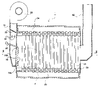
Fig. 1 is an explanatory longitudinal sectional view of a steam
boiler to which an embodiment of the present invention is applied;
Fig. 2 is an explanatory cross-sectional view taken along the
line II-II of Fig. 1;
Fig. 3 is a schematic structural view of a pilot burner according
12
CA 02538713 2006-03-07
to this embodiment; and
Fig. 4 is a schematic structural view of a pilot burner according
to another embodiment of the present invention.
DETAILED DESCRIPTION OF THE PREFERRED EMBODIMENTS
In the following, embodiments to which the combustion apparatus
of the present invention is applied will be described with reference
to the drawings.
Fig. 1 is an explanatory longitudinal sectional view of a steam
boiler to which an embodiment of the present invention is applied,
and Fig. 2 is an explanatory cross-sectional view taken along the
line II-II of Fig. 1.
As shown in Figs. land 2, a boiler 1 according to this embodiment
is composed of a complete premix type burner 10 ( corresponding to
the "main burner" of the present invention) having a flat premixed
gas ejection surface (a flat combustion surface in which premixed
gas ejection holes are formed substantially in the same plane) ,
a boiler body 20 formed by using a large number of heat absorbing
water tubes (heat transfer tubes) 21, 22, and 23, a blower 30 provided
for the purpose of sending combustion air to the burner 10, a chimney
portion 40 provided for the purpose of discharging exhaust gas inside
the boiler body 20 to the exterior of the boiler 1. In addition,
in this embodiment, a pilot burner 50 as an ignition means for the
burner 10 is provided in close proximity to the burner 10. The burner
13
CA 02538713 2006-03-07
and the pilot burner 50 correspond to the "combustion apparatus"
of the present invention. In Figs. 1 and 2, a fuel supply route
and an air supply route constituting a part of the pilot burner
50 are omitted so that the drawings may not be complicated.
The burner 10 constituting the boiler 1 of this embodiment
is a premixed gas burner having a premixed gas ejection surface
in which premixed gas ejection holes are formed substantially in
the same plane, and is formed by alternately stacking together
corrugated plates and flat plates. With this construction, a large
number of premixed gas ejection holes are formed in the premixed
gas ejection surface (combustion surface) 10a of the burner 10.
The burner 10 is provided in close proximity to the water tubes
(water tube groups) forming the boiler body 20. Although a detailed
description of its structure, etc. is omitted here, the burner 10
of this embodiment has a construction similar to that of the
"combustion burner" as disclosed in JP 3221582 B. Further, although
a specific description of its structure is omitted, the burner 10
of this embodiment is formed so as to be capable of executing low
combustion and high combustion through adjustment of the amount
of gas fuel supplied and the amount of combustion air. Further,
in the burner 10 capable of thus establishing combustion states
in a number of stages, a low combustion state is first attained
at the start of combustion, and then transition to a high combustion
state is effected.
14
CA 02538713 2006-03-07
. .
The boiler body 20 constituting the boiler 1 of this embodiment
is formed by using an upper header 24, a lower header 25, a plurality
of water tubes (outer water tubes 21, inner water tubes 22, and
central water tubes 23) arranged upright between the upper and lower
headers 24 and 25, etc. Inside the boiler body 20, the outer water
tubes 21, the inner water tubes 22, and the central water tubes
23 are arranged in the gas flowing direction ( the longitudinal
direction of the boiler body 20) , and inner water tube groups (water
tube groups formed by using the inner water tubes 22) and outer
water tube groups (water tube groups formed by using the outer water
tubes 21) are formed, each in two rows, on either side of a central
water tube group (a water tube group formed by using the central
water tubes 23) . The adjacent water tubes are arranged in zigzag
form.
Further, as shown in Fig. 2, in the boiler body 20 of this
embodiment, there are formed a pair of water tube walls 27 by using
the outer water tubes 21 extending on either side in the longitudinal
direction of the boiler body 20 and connecting portions 26 connecting
the outer water tubes 21 to each other. By using the pair of water
tube walls 27 and the upper and lower headers 24 and 25, there is
formed in the boiler body 20 a substantially rectangular gas flowing
space 29, in which the inner water tubes 22 and the central water
tubes 23 are arranged at predetermined intervals.
Further, as shown in Fig. 2, in the boiler body 20 of this
CA 02538713 2006-03-07
embodiment, there is provided a non-tube region 28 formed by removing
some of the inner water tubes 22. In this embodiment, the non-tube
region 28 is formed by removing two to four water tubes with a diameter
(outer diameter) of approximately 60 mm from each of the inner water
tube group in the gas flowing direction. The reason for forming
the non-tube region 28 is to control the gas staying time. In this
embodiment, the non-tube region 28 is formed such that a gas at
a temperature of approximately 1300 C is allowed to stay within
the boiler body 20 for approximately 15 msec. That is, the non-tube
region 28 is provided in order to secure the combustion space.
In the boiler body 20, constructed as described above, the
gas is cooled by the water tubes 21, 22, and 23 in close proximity
to the burner 10 to suppress the gas temperature, thereby making
it possible to realize a reduction in NOx. In addition, in this
boiler body 20, the gas oxidation reaction after abrupt cooling
is promoted at the non-tube region 28, so it is also possible to
realize a reduction in CO.
The blower 30 constituting the boiler 1 of this embodiment
is provided in order to supply combustion air to the burner 10,
and the blower 30 and the burner 10 are connected by using an air
supply portion 31. In the air supply portion 31, there are provided
gas fuel supply tubes 32, in which there are provided fuel adjusting
valves (not shown) for adjusting the fuel flow rate for high combustion
and low combustion.
16
CA 02538713 2006-03-07
4
Further, in the air supply portion 31, there is provided a
damper 33 for adjusting the amount of air supplied from the blower
30 to the burner 10. The damper 33 is formed so as to be rotatable
within the air supply portion 31. By adjusting the degree of opening
of the air supply portion 31, the amount of air supplied to the
burner 10 is controlled. Although omitted in Fig. 1, on the upstream
side of the damper 33, there is provided one end of an air supply
route for supplying air to the pilot burner 50.
The chimney portion 40 constituting the boiler 1 of this
embodiment is provided on the most downstream side of the boiler
body 20 such that the inlet thereof is opposed to the burner 10.
Thus, in the boiler 1 of this embodiment, the gas generated at the
burner 10 is brought into linear contact with the water tubes 21,
22, and 23 constituting the boiler body 20 (to undergo heat exchange
through contact), and is then discharged to the exterior of the
boiler 1 through the chimney portion 40 as exhaust gas.
Thepilotburner50 constitutingtheboiler 1 of this embodiment
is formedas a cylinder , the forwardendportion ( premixedgas ejecting
portion 50a) of which is provided in close proximity to the burner
10. To be more specific, it is formed as shown in Fig. 3. Fig.
3 is a schematic structural view of the pilot burner of this
embodiment.
As shown in Fig. 3, the pilot burner 50 of this embodiment
is equipped with a premixed gas ejecting portion 50a provided in
17
CA 02538713 2006-03-07
,
close proximity to the premixed gas ejection surface 10a of the
burner 10, and a premixed gas mixing portion 50b communicating with
the premixed gas ejecting portion 50a. Connected to the premixed
gas mixing portion 50b are a fourth air supply route 64 and a gas
fuel supply route 65.
The fourth air supply route 64 provided for the purpose of
supplying combustion air to the pilot burner 50 is connected to
a second air supply route 62 and a third air supply route 63 that
are branched off from a first air supply route 61 provided on the
upstream side of the damper 33. Combustion air is supplied to the
premixed gas mixing portion 50b of the pilot burner 50 by way of
the first through third air supply routes 61, 62, and 63 and the
fourth air supply route 64. Provided in the second air supply route
62 are a first electromagnetic valve 71 (which corresponds to the
"supply amount adjusting means" of the present invention) and a
first orifice 72, and provided in the third air supply route 63
is a second orifice 73. Further, a second electromagnetic valve
74 and a third orifice 75 are provided in the gas fuel supply route
65 provided for the purpose of supplying gas fuel to the pilot burner
50.
In this embodiment, the amount of air supplied to the pilot
burner 50 as appropriate is adjusted by the first electromagnetic
valve 71 provided in the second air supply route 62, and the amount
of gas fuel supplied to pilot burner 50 is adjusted by the second
18
CA 02538713 2006-03-07
electromagnetic valve 74 provided in the gas fuel supply route 65.
The boiler 1 of this embodiment, constructed as described above,
provides the following operational effects.
In this embodiment, ignition of the pilot burner 50 is first
effected, and then ignition of the burner 10 is effected by using
the flame of the pilot burner 50. Low combustion or high combustion
is effected at the burner 10. Even in the case of high combustion,
transition from a low combustion state to a high combustion state
is effected. Thus, in either case , in this embodiment , low combustion
is first effected at the burner 10 by using the pilot burner 50.
When low combustion is effected at the burner 10, the amount
of gas fuel and the amount of combustion air supplied to the burner
are throttled as compared to those in the case of high combustion.
The amount of gas fuel is adjusted by the fuel adjusting valves
(not shown) provided in the gas fuel supply tubes 32, and the amount
of combustion air is adjusted by the degree of opening of the damper
33 in the air supply portion 31. That is, when supplying combustion
air needed for low combustion, the damper 33 is tilted from the
"open" state to the "closed" state, so the air pressure on the upstream
side of the damper 33 is higher at the time of low combustion than
at the time of high combustion.
As shown in Fig. 3, the first air supply route 61 for supplying
combustion air to the pilot burner 50 is branched off on the upstream
side of the damper 33, so when no special measure is taken (when,
19
CA 02538713 2006-03-07
for example, it is simply connected by piping) , high pressure air
is ejected from the pilot burner 50 at the combustion start (low
combustion start) of the burner 10, with the result that the ignition
and the combustion state of the pilot burner 50 itself become unstable.
However, in this embodiment, the first air supply route 61 is branched
off into the second air supply route 62 and the third air supply
route 63, and the orifices 72 and 73 are provided in the routes
62 and 63, respectively, so it is possible to supply proper combustion
air to the pilot burner 50 ( i.e. , the premixed gas mixing portion
50b thereof) in correspondence with the degree of opening of the
damper 33 at the time of low combustion.
In this embodiment, combustion air supplied through the air
supply routes 61, 62, 63, and 64 and gas fuel supplied through the
gas fuel supply route 65 as stated above are mixed at the premixed
gas mixing portion 50b, and a premixed gas is ejected from the forward
end portion of the pilot burner 50 ( the premixed gas ejecting portion
50a) formed in a cylindrical configuration. Then, by using an
ignition means, such as an ignition insulator (not shown) , ignition
is effected on the premixed gas ejected from the premixed gas ejecting
portion 50a of the pilot burner 50.
Then, the gas fuel supplied from the gas fuel supply tubes
32 and the air supplied from the blower 30 are mixed with each other
in the air supply portion 31, and a premixed gas prepared through
mixing here is supplied to the burner 10. In this process, gas fuel
CA 02538713 2006-03-07
is supplied from the gas fuel supply tubes 32 in an amount needed
for low combustion ( e . g . , approximately 30% to 50% of high combustion) .
The adjustment of the supply amount of gas fuel is effected by a
fuel adjusting valve (not shown). Air is supplied from the blower
30 in an amount needed for low combustion.
The premixed gas ejected from the premixed gas ejection surface
10a of the burner 10 is ignited by the pilot burner 50, and a gas
F undergoing combustion reaction accompanied by a flame is formed
at the burner 10. The premixed gas is ejected from the burner 10
so as to be substantially perpendicular (orthogonal) to the water
tubes 21, 22, and 23 in the boiler body 20, so the gas F undergoing
combustion reaction is repeatedly brought into contact with the
water tubes 21, 22, and 23 in the boiler body 20 so as to cross
them (to effect heat exchange with the water tubes), and is then
turned into exhaust gas. Then, this exhaust gas is discharged to
the exterior of the boiler 1 through the chimney portion 40 provided
on the most downstream side of the boiler body 20.
After ignition of the burner 10 has been effected as described
above, a low combustion state is maintained or transition from a
low combustion state to a high combustion state is effected at the
burner 10, thus maintaining the requisite combustion state for the
boiler 1. After the ignition of the burner 10 has been confirmed,
the pilot burner 50 attains its objective as the "ignition means",
so the supply of gas fuel to the pilot burner 50 is stopped. To
21
CA 02538713 2006-03-07
= .
be more specific, the second electromagnetic valve 74 of the gas
fuel supply route 65 is closed, and the supply of gas fuel is stopped.
When the supply of gas fuel is stopped as described above,
solely "air" is ejected from the forward end portion of the pilot
burner 50 (the premixed gas ejecting portion 50a). Here, if no
special measure is taken for the pilot burner (see the prior-art
technique), the combustion state of the burner 10 becomes unstable
due to the "air" thus ejected, and various problems as stated above
(e.g., generation of CO) are involved.
However, in this embodiment, the first electromagnetic valve
71 is provided in the second air supply route 62, so, by appropriately
adjusting the opening/closing state of the first electromagnetic
valve 71, it is possible to maintain a satisfactory combustion state
for the burner 10 without involving any problems as in the prior
art. To be more specific, the second electromagnetic valve 74 of
the gas fuel supply route 65 is closed to stop the supply of gas
fuel and, at the same time, the first electromagnetic valve 71 of
the second air supply route 62 is also closed to reduce the amount
of air supplied through the second air supply route 62 to "zero".
With this construction, solely the slight amount of air supplied
through the third air supply route 63 is ejected from the forward
end portion of the pilot burner 50 (the premixed gas ejecting portion
50a).
The amount of air supplied through the third air supply route
22
CA 02538713 2013-05-03
63 is an amount which does not adversely affect the combustion state
of the burner 10 and which allows cooling of the pilot burner 50.
That is, air is supplied through the third air supply route 63 in
an amount necessary for appropriately cooling the pilot burner 50,
which is thermally influenced by the burner 10, and improving the
durability of the pilot burner 50.
Thus, the opening diameter of the second orifice 73 of this
embodiment is set so as to provide an amount of air which does not
adversely affect the combustion state of the burner 10 and which
allows cooling of the pilot burner 50. Further, the opening diameter
of the first orifice 72 is set so as to provide an amount of air
making it possible for the pilot burner 50 to maintain a proper
combustion state when combined with the amount of air from the third
air supply route 63 ( the amount of air based on the opening diameter
of the second orifice 73) .
As described above, in this embodiment, at the time of extinction
of the pilot burner 50, not only is the supply of gas fuel stopped, but also
the supply amount of combustion air is controlled by using the first
electromagnetic valve 71. In this control, the supply amount of
combustion air is an amount which does not adversely affect the
combustion state of the burner 10 and which allows cooling of the pilot
burner 50.
Thus, according to this embodiment, even with a construction
in which the pilot burner 50 is provided in the vicinity of the
23
CA 02538713 2006-03-07
burner 10 (main burner) , no air from the pilot burner 50 is blown
against the flame formed by the burner 10 to cause a local reduction
in flame temperature, and it is possible to suppress generation
of CO and unburned substances.
In addition, the pilot burner 50 is supplied with a slight
amount of air capable of cooling the pilot burner 50 itself, so
the pilot burner 50, which is provided at a position in close proximity
to the flame of the burner 10, is appropriately cooled, thereby
improving its durability.
In particular, according to this embodiment, a remarkable
effect is obtained in "low combustion" or in "a low capacity model",
in which the amount of air from the pilot burner 50 increases with
respect to the load of the burner 10 (main burner) . Further,
according to this embodiment, at the time of low combustion, the
CO rising point in the exhaust gas ( the point where the amount of
CO begins to exhibit a tendency to increase) is on the high 02 side,
and a reduction in CO is achieved with the 02 set at high level.
The present invention is not restricted to the embodiment modes
and the embodiment described above but allows various modifications
as needed without departing from the gist of the invention, and
all of such modifications are covered by the technical scope of
the present invention.
While in the embodiment described above the pilot burner 50
provided in close proximity to the burner 10 is formed as a cylindrical
24
CA 02538713 2006-03-07
burner, the present invention is not restricted to this construction
but is applicable as needed to pilot burners of various constructions.
For example, it is also applicable to a construction as shown in
Fig. 4.
Fig. 4 is a schematic structural view of a pilot burner according
to another embodiment. This embodiment is basically of the same
construction as the one described above (see Fig. 3, etc.) except
for a pilot burner 80, so, in the following, the components that
are the same as those of the above embodiment are indicated by the
same reference symbols, and a description thereof will be omitted.
The following description will be mainly focused on the features
of this embodiment.
As shown in Fig. 4, the pilot burner 80 of this embodiment
is equipped with a premixed gas ejection surface 80a provided
substantially in the same plane as the premixed gas ejection surface
10a of the burner 10, and a premixed gas mixing portion 80b
communicating with the premixed gas ejection surface 80a, and
connected to the premixed gas mixing portion 80b are the fourth
air supply route 64 and the gas fuel supply route 65.
Like the burner 10, the pilot burner 80 is a premixed gas burner
having a premixed gas ejection surface in which premixed gas ejecting
holes are formed substantially in the same plane, and is formed,
for example, by alternately stacking together corrugated plates
and flat plates. Thus, it may be formed integrally with the burner
CA 02538713 2006-03-07
10, using a part of the integral unit as the pilot burner 80, or
it may be formed separately from the burner 10, forming the pilot
burner 80 so as to be in close contact with the burner 10. Further,
the pilot burner 80 may be formed, for example, by using a ceramic
plate having a large number of ejecting holes through which premixed
gas is ejected.
As in the embodiment described with reference to Fig. 3, etc.,
in the pilot burner 80 of this embodiment, constructed as described
above, combustion air supplied through the air supply routes 61,
62, 63, and 64 and gas fuel supplied through the gas fuel supply
route 65 are mixed at the premixed gas mixing portion 80b, and premixed
gas is ejected from the premixed gas ejection surface 80a of the
pilot burner 80. Then, by using an ignition means, such as an ignition
insulator (not shown) , and ignition is effected on the premixed
gas ejected from the premixed gas ejection surface 80a of the pilot
burner 80.
After the burner 10 has been ignited by using the pilot burner
80, the supply of gas fuel is stopped, and the amount of air to
be supplied to the pilot burner 80 is controlled by using the first
electromagnetic valve 71 provided in the second air supply route
62.
The pilot burner 80 of this embodiment, which is constructed
and functions as described above, can provide the same effect as
that of the embodiment described with reference to Fig. 3, etc.
26
CA 02538713 2006-03-07
While in the above-described embodiments, the first
electromagnetic valve 71 is provided in the air supply route 62
connected to the pilot burner 50 and 80 to control the supply air
amount, the present invention is not restricted to this construction.
It is possible to adopt any other construction as long as it is
capable of controlling the amount of air supplied to the pilot burner.
Thus, for example, it is also possible to adopt a construction in
which opening/closing means, such as a shutter, is provided at the
forward end of the pilot burner.
Further, while in the above-described embodiments a slight
amount of air for cooling the pilot burner is supplied to the interior
of the pilot burner, the present invention is not restricted to
this construction. As long as the cooling of the pilot burner is
possible, the amount of air inside the pilot burner may be "zero".
Thus, for example, it is possible to adopt a construction in which,
at the time of extinction of the pilot burner, the amount of air
supplied to the interior of the pilot burner is reduced to zero,
with air for cooling the pilot burner being supplied to the outer
side of the pilot burner.
Further, while in the above-described embodiments the air
supply is effected by way of the first air supply route 61 and the
second and third air supply routes 62 and 63 branched off from the
first air supply route 61, the present invention is not restricted
to this construction. Thus, for example, in Figs. 3 and 4, it is
27
CA 02538713 2006-03-07
also possible to adopt a construction in which no third air supply
route 63 is provided. When adopting such a construction, it is
desirable to provide a supply amount adjusting means not only capable
of opening/closing the route but also capable of adjusting the air
amount as appropriate (that is, capable of adjusting the so-called
degree of opening of the route) . Examples of such a supply amount
adjusting means include a damper, a ball valve (one capable of
adjusting degree of opening or one equipped with a through-hole
so that a slight amount of air may flow therethrough in the closed
state), and a flow rate switching valve (one equipped with a
through-hole so that a slight amount of air may flow therethrough
with the electromagnetic valve closed) . With such a construction,
when igniting the pilot burner, the air supply route is opened to
a corresponding degree of opening to supply air, and, when
extinguishing the pilot burner, the degree of opening is adjusted
so as to make it possible to supply the requisite amount of air
for cooling the pilot burner. Further, as needed, it is also possible
to bring the route into a totally closed state, reducing the amount
of air supplied to the pilot burner to zero. The present invention
does not exclude a construction in which the second air supply route
62 is provided with a supply amount adjusting means (e.g., an
electromagnetic valve) that simply opens/closes the route, and it
is also possible to adopt a construction in which, in addition to
such a supply amount adjusting means, an element capable of supplying
28
CA 02538713 2006-03-07
=
cooling air to the exterior (or the interior) of the pilot burner
is provided.
Further, while in the above-described embodiments the boiler
1 is a steam boiler, this should not be construed restrictively.
The present invention is also applicable to a hot water boiler.
Further, while in the embodiment modes and the embodiments
described above the combustion apparatus of the present invention
is applied to a boiler, this should not be construed restrictively.
Thus, it is possible to apply the combustion apparatus of the present
invention to some other apparatus, for example, a thermal component,
such as a water heater or the reheater of an absorption refrigerating
machine.
29