Language selection

Search

Patent 2538901 Summary

Third-party information liability

Some of the information on this Web page has been provided by external sources. The Government of Canada is not responsible for the accuracy, reliability or currency of the information supplied by external sources. Users wishing to rely upon this information should consult directly with the source of the information. Content provided by external sources is not subject to official languages, privacy and accessibility requirements.

Claims and Abstract availability

Any discrepancies in the text and image of the Claims and Abstract are due to differing posting times. Text of the Claims and Abstract are posted:

  • At the time the application is open to public inspection;
  • At the time of issue of the patent (grant).
(12) Patent: (11) CA 2538901
(54) English Title: IMPROVEMENT FOR EYE GLASS FRAME ADAPTED FOR THE REMOVAL AND INSERTION OF LENSES
(54) French Title: AMELIORATION APPORTEE A UNE MONTURE DE LUNETTES ADAPTEE AU RETRAIT ET A L'INSERTION DE VERRES
Status: Expired and beyond the Period of Reversal
Bibliographic Data
(51) International Patent Classification (IPC):
  • G02C 01/08 (2006.01)
(72) Inventors :
  • WHITE, ROBERT (United States of America)
  • LACASSE, RUSSELL (United States of America)
  • WEDECK, DAVID (United States of America)
(73) Owners :
  • TRANSFRAME LIMITED LIABILITY COMPANY
(71) Applicants :
  • TRANSFRAME LIMITED LIABILITY COMPANY (United States of America)
(74) Agent: SMART & BIGGAR LP
(74) Associate agent:
(45) Issued: 2009-12-15
(86) PCT Filing Date: 2005-02-03
(87) Open to Public Inspection: 2006-08-03
Examination requested: 2006-03-14
Availability of licence: N/A
Dedicated to the Public: N/A
(25) Language of filing: English

Patent Cooperation Treaty (PCT): Yes
(86) PCT Filing Number: PCT/US2005/003276
(87) International Publication Number: US2005003276
(85) National Entry: 2006-03-14

(30) Application Priority Data: None

Abstracts

English Abstract


This invention provides for making a cam arm with
a wave-shaped or curved portion adapted to fit within a
recess on the top of the upper closure block of the frame so
that the frame eyewire is securely closed in place.


French Abstract

La présente invention concerne un bras de came (612) avec une partie ondulée ou courbe (813) qui peut être encastré dans une rainure ou fixé sur le dessus du bloc de fermeture supérieur de la monture, de manière à verrouiller solidement la partie cercle de la monture. Le bras de came (612) est fabriqué dans un matériau élastique approprié qui permet de fixer le bras même si la circonférence du verre dépasse légèrement la longueur prévue.

Claims

Note: Claims are shown in the official language in which they were submitted.

CLAIMS:
1. An eyeglass frame having lenses and a frame
eyewire, with a lower eyewire closure block and an upper
eyewire closure block comprising a cam mechanism including a
cam lock formed of a pair of cam heads connected to an arm of
said cam lock, a hinge pin extending through a hole in the closure
block of said frame, said pair of cam heads being pivotally
connected to said hinge pin and to said lower eyewire closure
block by a pivot point so that when said cam arm is moved in a
first direction said cam heads rotate away from said lower
eyewire closure block and cause said lower eyewire closure block
and said upper eyewire closure block to separate a distance
thereby opening said frame eyewire for a lens to be removed,
inserted or replaced; and said arm being moved to a second
position opposite said first position which cause said cam heads
to rotate back into engagement against said lower eyewire
closure block thereby causing said lower eyewire closure block to
come together with said upper eyewire closure block and said
frame to close, the improvement comprising:
said cam arm including a rounded or wave-shaped
portion adapted to be fitted on top of or within a recess in said
upper eyewire closure block of said frame to provide for a more
secure closure of said frame while making allowance for said lenses
being slightly over cut and to prevent accidental opening
of said frame.
-8-

2. The frame according to claim 1 wherein said cam
arm is made from a suitable elastic material to enable said
frame to lock securely even if said lens is over-cut and to
provide clamping force to keep the upper and lower eyewire
closure blocks pressed together.
3. The frame according to claim 2 wherein said
suitable elastic material is spring steel.
4. The frame according to claim 1 wherein said
frame further includes a non-threaded hinge pin to insure proper
alignment of said cam arm and a groove cut into said upper and
lower eyewire closure blocks.
-9-

Description

Note: Descriptions are shown in the official language in which they were submitted.


CA 02538901 2008-09-30
Improvement for Eye glass Frame Adapted for the
Removal and Insertion of Lenses
BACKGROUND OF THE INVENTION
1. Field of the Invention
The present invention relates to an important improvement
on an eyeglass frame in which a latching mechanism is applied to
the eyewire portion of the frame to permit the insertion, removal
or replacement of the lenses in the frame. In particular, the
present invention provides a much more secure closure to retain
the lenses in the frame, allows slightly over cut lenses to be
inserted and retained, and closes in such a way that the frame
will not accidentally open.
2. The Related Prior Art
US Patent 6273564 describes an eyeglass frame for the
removal and insertion of lenses that provides for a portion of the
frame removably coupled to the body of the frame to permit the
insertion, removal or replacement of the lenses
-1-

CA 02538901 2008-09-30
in the frame. It would be most desirable to provide for a secure
closure of the frame eyewire so that the frame portion which
could be opened is able to accept lenses that have been cut
slightly over retain the lenses securely, prevent accidental
release, yet still be able to be easily opened with readily available
tools. The present invention provides for such a feature.
SUMMARY OF THE INVENTION
The principal object of the present invention provides a
modification of the design of US Patent 6273564 in which a more
secure closure is provided that will accept oversized lenses and
not accidentally open which could be integrated into the current
design in the aforementioned patent.
This invention importantly provides for utilizing a cam arm
made from a suitably elastic metal with a wave-shaped or curved
portion adapted to fit on top of or within a recess on the top of the
upper portion of the eyewire closure blocks so that the frame
eyewire is securely closed in order to retain the lenses.
The wave shaped cam arm, when made with suitably
elastic metal, can accept lenses that have been cut slightly over-
size in terms of having a longer circumference than the inside of
the eyewire. When closed, the cam arm will exert a constant force
to hold the upper and lower closure blocks
-2-

CA 02538901 2008-02-06
together, which provides for a more secure fit. The design will
prevent accidental release, yet can be easily opened using
readily available tools, In addition fewer parts are required, end
standard manufacturing processes can be used,
BRIEF DESCRIPTION OF THE DRAWINGS
Fig. 1 shows a partial front view of the latching
mechanism of the frame;
Fig. 2 shows a partial rear view of the latching
mechanism of the partial sectional view in a closed position;
Fig. 3 shows a sectional view of the latching mechanism
of the frame taken along the lines 3-3 of FIG. 2;
Fig. 4 shows an elevated rear view taken along lines 4-4
of Fig. 3 showing the cam arts is closed along with the closed
upper and lower closure blocks of the frame;
Fig. 5 is a sectional view taken along lines 5-5 of Fig. 3
showing the cam arm and hinge pin, and the recesses in the
upper and lower closure blocks;
Fig. 6 shows a top view taken along lines 6-6 of Fig, 4
showing the frame in the closed position;
-3-

CA 02538901 2008-02-06
Fig. 7 is a sectional view taken along lines 7-7 of Fig. 5 of
the latching mechanism of the frame shown from the opposite
side of Fig. 3;
Fig. 8 is a rear view of the latching mechanism of the
frame in an open position showing the gap created in the closure
blocks and eyewire;
Fig. 9 is a sectional view along lines 9-9 of Fig. 8 in the
open position;
Fig. 10 is a top view along lines 10-10 of Fig. 8 in the
open position showing the top of the hinge pin and the recess in
the top closure block; and
Fig, 11 is an exploded view of the latching mechanism of
the frame.
-4-

CA 02538901 2008-02-06
DETAILED DESCRIPTION OF THE PREFERRED EMBODIMENT(S)
Referring to the drawings of Figures I-11, the present invention
provides a substantial modification to the design, in US Patent
6,273.564.
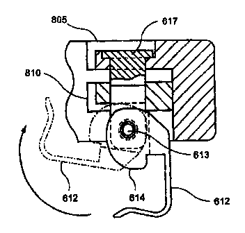
As shown in FIGS. 1-7, a latching cam lock 616 is
provided for an eyeglass frame 860. The cam lock 616 has a top
cam arm portion 813 that is curved or wave-shaped to fit into a
recess in the top of the upper closure block 805. Fig. 7 shows
the same view as Fig. 3 but from the other side.
The cam arm 612 is made of a suitable elastic material
such as spring steel. the purpose of which is by providing a cam
arm with the aforementioned wave-shaped portion and made of
a suitable elastic material enables the cam arm 612 to latch
even if the lens circumference is slightly larger than ideal. This
enables the lenses to be over-cut up to 0.25mm (or more) and
still be able to (i) enable the cam arm 612 to close (see Fig. 4),
even if the lenses are cut with a larger circumference than
optimal; (ii) exert a load in order to keep the upper closure
block 805 and lower closure block 810 (which corresponds
roughly to elements 605 and 610 in US Patent 6,273.564) mated
together; (iii) enable the cam lock to provide a more secure
closure to prevent accidental opening; and (iv) enable the cam
lock to be opened using readily available tools such as a small,
slot-blade screwdriver.
-5-

CA 02538901 2008-02-06
The suitable elastic material for the cam arm 612 is
strong enough to hold the cam arm 612 in place once it has
been securely set, but enables some degree of give in the event
that the lens is over-cut. Spring steel is a good materiel to use
for this application, although other suitably elastic material can
work. The elasticity in the cam arm 612 also provides for
clamping force to keep the closure blocks 805, 812 securely
together.
The hinge pin is a non-threaded pin 617 (see Figs. 5, and
7) to eliminate the need for a threaded post. This enables a
reduction in the overall height of the design, and insures proper
alignment of the cam arm 612 and the groove cut into the back
of the upper and lower closure blocks, 805 and 810,
respectively.
By securing the cam arm into the recess on the top of the
upper closure block 805 the cam arm is securely locked in place
which ensures that the frame closure blocks are not accidentally
opened which can cause the release of the lens. Instead the
closure blocks are held together under load (see FIG. 3) thereby
preventing the lenses from dropping out of the frame
unintentionally.
Fig. 8 shows e portion of the frame in the open
_6_

CA 02538901 2008-02-06
position. Fig. 9 shows the cam arm 612 rotating from the open
position (solid lines) toward the closed position (dotted lines).
Fig. 10 is a top view of the hinge pin. Fig. 11 is an exploded
view showing the mechanism for the present invention.
Figure 11 is an exploded view in which the cam 614 is
attached to hinge pin 617 by pivot pin 613. This enables the
cam arm 612 to swing up and fit into the recess in the back and
top of the upper and lower closure blocks 805 and 810,
respectively. This action pulls the upper and lower blocks 805
and 810 together.
While presently preferred embodiments have been
described for purposes of the disclosure, numerous changes in
the arrangement of method steps and apparatus parts can be
made by those skilled in the art. Such changes are
encompassed within the spirit of the invention as defined by the
appended claims.
-7-

Representative Drawing
A single figure which represents the drawing illustrating the invention.
Administrative Status

2024-08-01:As part of the Next Generation Patents (NGP) transition, the Canadian Patents Database (CPD) now contains a more detailed Event History, which replicates the Event Log of our new back-office solution.

Please note that "Inactive:" events refers to events no longer in use in our new back-office solution.

For a clearer understanding of the status of the application/patent presented on this page, the site Disclaimer , as well as the definitions for Patent , Event History , Maintenance Fee  and Payment History  should be consulted.

Event History

Description Date
Time Limit for Reversal Expired 2012-02-03
Letter Sent 2011-02-03
Grant by Issuance 2009-12-15
Inactive: Cover page published 2009-12-14
Inactive: Final fee received 2009-09-17
Pre-grant 2009-09-17
Inactive: Office letter 2009-03-17
Letter Sent 2009-03-17
Notice of Allowance is Issued 2009-03-17
Inactive: Approved for allowance (AFA) 2009-03-03
Amendment Received - Voluntary Amendment 2008-09-30
Inactive: S.30(2) Rules - Examiner requisition 2008-09-05
Amendment Received - Voluntary Amendment 2008-02-06
Inactive: S.30(2) Rules - Examiner requisition 2007-08-06
Inactive: S.29 Rules - Examiner requisition 2007-08-06
Application Published (Open to Public Inspection) 2006-08-03
Inactive: Cover page published 2006-08-02
Inactive: IPC assigned 2006-06-08
Inactive: First IPC assigned 2006-06-08
Inactive: Inventor deleted 2006-04-10
Letter Sent 2006-04-10
Inactive: Acknowledgment of national entry - RFE 2006-04-06
Letter Sent 2006-04-04
Application Received - PCT 2006-04-03
All Requirements for Examination Determined Compliant 2006-03-14
Request for Examination Requirements Determined Compliant 2006-03-14
National Entry Requirements Determined Compliant 2006-03-14

Abandonment History

There is no abandonment history.

Maintenance Fee

The last payment was received on 2009-01-07

Note : If the full payment has not been received on or before the date indicated, a further fee may be required which may be one of the following

  • the reinstatement fee;
  • the late payment fee; or
  • additional fee to reverse deemed expiry.

Patent fees are adjusted on the 1st of January every year. The amounts above are the current amounts if received by December 31 of the current year.
Please refer to the CIPO Patent Fees web page to see all current fee amounts.

Fee History

Fee Type Anniversary Year Due Date Paid Date
Basic national fee - standard 2006-03-14
Request for examination - standard 2006-03-14
Registration of a document 2006-03-14
MF (application, 2nd anniv.) - standard 02 2007-02-05 2006-11-14
MF (application, 3rd anniv.) - standard 03 2008-02-04 2007-12-20
MF (application, 4th anniv.) - standard 04 2009-02-03 2009-01-07
Final fee - standard 2009-09-17
MF (patent, 5th anniv.) - standard 2010-02-03 2009-12-29
Owners on Record

Note: Records showing the ownership history in alphabetical order.

Current Owners on Record
TRANSFRAME LIMITED LIABILITY COMPANY
Past Owners on Record
DAVID WEDECK
ROBERT WHITE
RUSSELL LACASSE
Past Owners that do not appear in the "Owners on Record" listing will appear in other documentation within the application.
Documents

To view selected files, please enter reCAPTCHA code :


To view images, click a link in the Document Description column. To download the documents, select one or more checkboxes in the first column and then click the "Download Selected in PDF format (Zip Archive)" or the "Download Selected as Single PDF" button.

List of published and non-published patent-specific documents on the CPD .

If you have any difficulty accessing content, you can call the Client Service Centre at 1-866-997-1936 or send them an e-mail at CIPO Client Service Centre.


Document
Description 
Date
(yyyy-mm-dd) 
Number of pages   Size of Image (KB) 
Description 2006-03-13 7 136
Abstract 2006-03-13 1 6
Claims 2006-03-13 2 37
Drawings 2006-03-13 5 62
Representative drawing 2006-06-08 1 9
Claims 2008-02-05 2 42
Description 2008-02-05 7 147
Description 2008-09-29 7 159
Claims 2008-09-29 2 46
Abstract 2009-03-16 1 6
Representative drawing 2009-11-22 1 10
Acknowledgement of Request for Examination 2006-04-03 1 190
Notice of National Entry 2006-04-05 1 230
Courtesy - Certificate of registration (related document(s)) 2006-04-09 1 128
Reminder of maintenance fee due 2006-10-03 1 110
Commissioner's Notice - Application Found Allowable 2009-03-16 1 163
Maintenance Fee Notice 2011-03-16 1 170
Fees 2006-11-13 1 29
PCT 2006-03-13 3 84
Fees 2007-12-19 1 31
Correspondence 2009-03-16 1 28
Fees 2009-01-06 1 37
Correspondence 2009-09-16 1 35
Fees 2009-12-28 1 35