Note: Descriptions are shown in the official language in which they were submitted.
CA 02538922 2006-03-08
Hydrogen Generating Apparatus
Field of the Invention
The present invention is directed to a hydrogen generating apparatus and in
particular a
hydrogen generating apparatus for a motor vehicle.
Back rg ound
Hydrogen generating apparatus have been used on motor vehicles to supplement
the fuel
used to drive the vehicle. The use of hydrogen as a supplemental fuel in motor
vehicle
engines has been proposed to increase the performance of the engine. Hydrogen
and
oxygen, when used as part of the air/fuel mixture for the operation of the
engine, have
been found to increase the performance of the engine by increasing the mileage
and by
reducing the amount of emissions from the engine. The hydrogen and oxygen may
be
generated through electrolysis of an aqueous solution with the gases given off
being
mixed with the charge of fuel and air supplied to the engine.
Although hydrogen generating apparatus have proven useful, there are certain
disadvantages that have limited their widespread acceptance. For example, some
vehicles such as larger trucks simply don't have the room to accommodate the
apparatus.
Summary of the Invention
In accordance with a broad aspect of the present invention, there is provided
a hydrogen
generating apparatus comprising: hydrogen generating cells mounted to form a
lower
region of the apparatus, auxiliary devices mounted above the hydrogen
generating cells
and grouped along one side of the device, an open area above the hydrogen
generating
cells alongside the devices, the open area being substantially devoid of
auxiliary devices;
and a housing about the hydrogen generating cells, the auxiliary devices and
the open
area, the housing extending over the auxiliary devices and extending down to
extend over
CA 02538922 2006-03-08
2
the open area such that the housing defines a first height over the open area
and a second
elevated height over the auxiliary devices.
In accordance with another broad aspect of the present invention, there is
provided a
hydrogen generating assembly comprising a stairs including a step, a hydrogen
generating apparatus positioned behind the stairs such that the step of the
stairs is
exposed for use in front of the hydrogen generating apparatus, the stairs
being adapted to
permit access to the hydrogen generating apparatus.
It is to be understood that other aspects of the present invention will become
readily
apparent to those skilled in the art from the following detailed description,
wherein
various embodiments of the invention are shown and described by way of
illustration. As
will be realized, the invention is capable for other and different embodiments
and its
several details are capable of modification in various other respects, all
without departing
from the spirit and scope of the present invention. Accordingly the drawings
and detailed
description are to be regarded as illustrative in nature and not as
restrictive.
Brief Description of the Drawings
Referring to the drawings wherein like reference numerals indicate similar
parts
throughout the several views, several aspects of the present invention are
illustrated by
way of example, and not by way of limitation, in detail in the figures,
wherein:
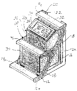
Figure 1 is a perspective view of a hydrogen generating assembly according to
one aspect
of the present invention;
Figure 2 is a side elevation of the assembly of Figure 1;
Figure 3 is a front elevation of the assembly of Figure 1;
DMSLega I\045401 \00084\2124545v2
CA 02538922 2006-03-08
3
Figure 4 is a schematic sectional view through a hydrogen generating apparatus
according to the present invention;
Figure 5A is a perspective view of a hydrogen generating apparatus with the
housing
removed;
Figure SB is an exploded perspective view of a hydrogen generating apparatus
according
to the present invention;
Figure 6A is a sectional view through a mounting configuration useful in the
present
invention and for hydrogen generating apparatus generally;
Figure 6B is an exploded perspective view showing an installation option
useful in the
present invention and for hydrogen generating apparatus generally;
Figure 7 is a schematic view of a component connector useful in the present
invention
and for hydrogen generating apparatus generally; and
Figure 8 is a perspective view of a pair of electrolysis electrode assemblies
including
electrode terminal connections according to one aspect of the present
invention. The
electrode assemblies are shown with their cell container sidewalk removed, but
mounted
on the cell's mounting base.
Detailed Descr~tion of Various Embodiments
The detailed description set forth below in connection with the appended
drawings is
intended as a description of various embodiments of the present invention and
is not
intended to represent the only embodiments contemplated by the inventor. The
detailed
description includes specific details for the purpose of providing a
comprehensive
understanding of the present invention. However, it will be apparent to those
skilled in
the art that the present invention may be practiced without these specific
details.
DMSLegal\045401100084\2124545v2
CA 02538922 2006-03-08
4
A hydrogen generating apparatus according to the present invention may be
formed and
configured to permit it to be integrated with or mounted behind the stairs on
a vehicle
such as a transport truck. A hydrogen generating assembly may include a
hydrogen
generating apparatus positioned behind, which may also be considered as
"under", a
vehicle's stairs so that the stairs remain open and operational for their
normal purpose to
access the cab or other components of the vehicle, but the space beneath the
stairs,
becomes useful for housing at Ieast some of the hydrogen generating components
of a
hydrogen generating assembly.
For example, one possible hydrogen generating assembly according to the
present
invention is illustrated in Figures 1 to 3. The assembly includes vehicle
stairs IO
including a support frame 12 and at least one step, which in the illustrated
embodiment
includes a lower step 14a, a middle step 14b and an upper step 14c. Vehicle
stairs may
also be termed a "ladder", but in any event includes at least one step.
The stairs are formed to define an open area 16 behind the steps. Support
frame 12 and
the steps may be formed to fill in about and substantially enclose open area
16 or, as
shown, support frame 12 and the steps may include openings 18 therebetween so
that the
open area may be accessed through the front and/or side of the stairs.
Support frame I2 may include mounting flanges 20, apertures 22, etc. to permit
stairs 10
to be secured to the vehicle.
The stairs may be constructed for their intended purpose so that they are
durable and
formed of appropriate materials such as of durable plastic, aluminum, steel,
chromed
materials, etc. formed by molding, casting, welding, fastening, or various
other means.
The size and shape of the stairs will depend on the desired distance between
the steps, the
number of steps, etc. and, thus, as will be appreciated, the stairs may vary
in size and
appearance as well as construction.
DMSLegal\04$401 \00084\2124545x2
CA 02538922 2006-03-08
A hydrogen generating apparatus 28 may be positioned in open area 16 defined
behind
the steps of the stairs. Generally, it will be required to access the
apparatus to maintain it.
Thus, the stairs may be adapted to permit access to the hydrogen generating
apparatus.
For example, the stairs may be adapted to be firmly installed but removable
from over the
apparatus, so that the apparatus can be accessed if need be by removal of the
stairs.
Hydrogen generating apparatus 28 may, in one embodiment, include a housing 30
including a cover 34 to positioned over an operation panel 32 (shown in
phantom behind
cover 34) through which the hydrogen generating apparatus is accessible for
some
maintenance and control thereof. In the illustrated embodiment, the housing is
formed to
fit into the shape defined behind the steps 14a, 14b, 14c with the operation
panel exposed
for access through an opening 18 between the steps of the stairs. In this
illustrated
embodiment of Figures 1 to 3, operation panel 32 of the hydrogen generating
apparatus is
accessible by opening its cover 34, which is positioned between two steps, the
middle
step 14b and the upper step 14c. As such, the operation panel is readily
accessible on the
front of the stairs, which is generally unobstructed on the vehicle.
Housing 30 may be formed to protect internal components of the hydrogen
generating
apparatus. For example, housing 30 may be formed of durable materials that
protect
against damage by kicking, weather and the rigors of being open on the side of
a motor
vehicle such as a transport truck. Housing 30 may also be formed to support
the weight
of an person standing thereon as may occur during use of the stairs by a
person. In the
illustrated embodiment, for example, the apparatus is formed to accommodate
stepping
thereon since the proximity and position of housing 30 to upper stair 14c may
present a
surface on which the operator may step. In one embodiment, for example, not
shown the
housing of the apparatus may become integral with the stairs so that at least
a portion of
the hydrogen generating apparatus housing acts as at least a portion of a step
and/or a
support frame. Such an embodiment is described below with respect to Figure 4.
Operation panel 32 may include locks, control buttons, fill ports, etc, as may
be desired
for operations such as filling, accessing, inspecting, controlling, etc. the
apparatus. Cover
DMSLegal\045401 \00084\2124545v2
CA 02538922 2006-03-08
6
34 may include locks 35, etc. to restrict unauthorized access to the operation
panel, if
desired.
The stairs may be permanently or removably mounted over the hydrogen
generating
apparatus. In one embodiment, the stairs are removably mounted over the
apparatus by
removable fasteners. For example in the illustrated embodiment, support frame
12
includes a rear frame 12a on which apparatus 28 is mounted and a portion 12b
of the
support frame having the steps 14a, 14b, 14c attached thereto is removably
mounted by
removable fasteners to the rear frame with housing 30 positioned therebetween.
With
this construction, support frame portion 12b including the steps can be
removed from its
position over the apparatus to facilitate access to the hydrogen generating
apparatus
and/or to permit removal of the apparatus from behind the stairs. Of course,
for
removable mounting other fasteners may alternately be used, such as hinges,
pivots,
latches, catches, locks, etc., as desired.
With reference to Figures 4 and SA and SB, to reduce the size of the assembly,
a
hydrogen generating apparatus may be internally sized and configured to fit
behind the
stairs in a compact form. Generally, a hydrogen generating apparatus includes
three main
groups of components: electrolysis cells 36 in which hydrogen gas generation
occurs
from a electrolyte solution by an electrolysis process conducted through
electrodes;
auxiliary devices (some of which are shown at 38) for controlling apparatus
operation, for
gas treatment, for controlling the characteristics of the conveyed gas, for
mounting
components, etc.; and conduits (a portion of which are shown at 40) for
conducting
generated gas from the cells to the engine. In many embodiments, a hydrogen
generating
apparatus housing 30a may contain cells 36 and at least a portion of the
devices 38 and
conduits 40 for the overall apparatus. In one embodiment to permit a compact
form and
to shape the apparatus for integration to a stairs, cells 36 may be installed
to form a lower
portion of the apparatus and some of the auxiliary devices 38 are mounted on
top of cells
36. Devices 38, may include, for example, any or all of a pressure switch 38a,
a filter
38b, a flame arrestor, a controller, a power converter, a heater, an
electrical bracket 38c,
an electrical cover 38d including control panel 32, etc.
DMSLega1104540110008412124545v2
CA 02538922 2006-03-08
7
The lower portion of the apparatus may include an upper facing surface above
the cells,
the upper facing surface may include side edges extending between a front edge
and a
back edge. Devices 38 may be mounted together on one side of the upper facing
surface
to form an open area, indicated by phantom lines 44. The open area may be
defined as
that area between the mounted position of devices 38 and the front edge of the
upper
facing surface. Open area 44 has few if any components mounted thereabove. For
example, in the illustrated embodiment of Figure SB, only a fastener protrudes
above the
upper surface of the lower portion in the open area. With this mounting
arrangement
wherein devices 38 are mounted on top of the cells, the plan area of the
apparatus is
reduced over an apparatus where the devices are mounted beside the cells, and
the
housing 30, 30a of the apparatus need only define a height Hl at one end which
includes
substantially only the height of cells 36 including their containers and
mounting and
access components. For example, in the illustrated embodiment of Figures SA
and SB,
the hydrogen generating cell containers are each formed from side walls 46c
mounted
between base 46a and top plate 46b. Side walls 46c may be formed from a tube
and the
side walls may be sealed at one end in a recess 46d (Figure 8) in base 46a and
sealed at
an opposite end in a recess formed in top plate 46b. The other higher side of
the
apparatus housing, which includes devices 38 mounted above the cells, defines
a height
H2 greater than height H1. This height change permits the side of the
apparatus with the
lower height, that with open area 44, to be fit under a step, such as a step
14d (or step 14b
in Figure 1), while the higher side of the apparatus, that with devices 38
installed above
cells 36, can be installed under a higher step, such as a step 14e (or step
14c in Figure 1),
in the stairs.
To ensure that open area 44 remains open, any connection points, such as
recesses 45a,
fastener apertures 45b and ports 45c, can be maintained to one side of top
plate 46b and
as much as possible away from the open area.
The conduits 40 may be positioned about the cells, through mounting components
46a,
46b, between the devices, etc. as may be desired. However, it is beneficial to
maintain
DMSL,ega!\045402 \00084\212454w2
CA 02538922 2006-03-08
8
the conduits close to the other components to reduce the overall size of the
apparatus. In
one embodiment, conduits may be formed through, as by drilling or forming,
mounting
and access components 46a, 46b. In the illustrated embodiment, for example,
some
conduits, which cannot be seen, for passage of generated hydrogen gas are
formed
through top plate 46b. Such conduits extend from cells 36 to a port 45c
opening to
pressure switch 38a, from which conduit 40 extends to filter 38b.
Housing 30a may be included about the hydrogen generating apparatus internal
components to protect them. Housing 30a may cover hydrogen generating cells
36,
auxiliary devices 38 and open area 44. The housing may form an elevated
surface over
the auxiliary devices and extends down, for example via a wall 50, to a lower
surface
extending over open area 44 such that the housing defines first height Hl over
the open
area and second elevated height H2 over the auxiliary devices. The height
change
renders the housing with a stepped form. In the illustrated embodiment of
Figure 4, wall
50 is substantially vertical and steps 14e and 14f are formed integral with
housing, as by
forming, fastening, welding, etc. such that the housing itself forms the
vehicle stairs.
Wall 50 can include an access door 34a, if desired.
The housing of a hydrogen generating apparatus may be removably or permanently
mounted to the stairs, such as to the frame 12 or to another part of the motor
vehicle in
various ways. A reality of the use of such hydrogen generating systems is that
they
undergo significant vibration when on the vehicle. It has been determined that
such
vibration may cause premature component failure in a hydrogen generating
system.
Thus, component connectors may be used in the hydrogen generating apparatus
that
include a structural fastening member and a shock absorbing member in
association with
the structural fastening member to damp vibration from the vehicle to the
hydrogen
generating components. The structural fastening member and the shock absorbing
member may act between a first member of the apparatus and a second member on
the
apparatus, vehicle stair or vehicle. For example, in one embodiment it may be
useful to
provide a shock absorbing means when mounting the housing to damp apparatus 28
from
some vehicle vibration. In another embodiment, a combination of a structural
fastening
DMSLegal\045401 \00084\2124545v2
CA 02538922 2006-03-08
9
member and a shock absorbing member may be used for securing components within
the
hydrogen generating apparatus.
With reference to Figure 6A, in one embodiment a mounting configuration may be
used
that includes a structural fastening member 60 securing between housing 30 and
the point
of installation, in this case frame 12, and a shock absorbing member 62
disposed between
housing 30 and the point of installation. The shock absorbing member may be
positioned
adjacent or about the structural fastening member. In the illustrated
embodiment, shock
absorbing member 62 is positioned as an elastomeric sleeve about the
structural fastening
member to act between housing 30 and frame 12. Also, in the presently
illustrated
embodiment, shock absorbing member 62 includes an extension 64 acting between
frame
12 and structural fastening member 62 to also absorb shock therebetween.
Structural fastening member 60 is formed to secure housing 30 to frame 12 even
without
the use of the shock absorbing member such that should the shock absorbing
member
become deteriorated or break away, housing 30 will remain connected to the
point of
installation. For example in the illustrated embodiment, structural fastening
member 60
includes a steel bolt 66 connected, as by threaded engagement, welding etc, to
housing
30. Bolt 66 extends through an aperture 68 in frame 12 and a washer 70 and
bolt 72 are
threaded onto the end of bolt 66 to secure it through aperture 68. A rubber
washer 65
provides further shock absorption between washer 70 and frame 12.
Of course, shock absorbing member 62 and washer 65 could be formed as a one
piece
item, if desired, although installation may be more difficult than the
multiple piece
configuration as shown.
In another embodiment illustrated in Figure 6B, the housing may include a
plurality of
external legs 80 secured thereto, as by each including a bolt passing through
an aperture
in the housing (cannot be seen in any view) and engaging the leg. To secure
the housing
to stairs frame 12a, a lower bolt 82 may pass through washers 70, 70a, a shock
absorbing
rubber washer 65a and a shock absorbing rubber sleeve 62a before threading
into each
DMSL.egal\045401 \00084~124545v2
CA 02538922 2006-03-08
leg. The inner diameter 83 of rubber sleeve 62a may be formed frustoconically
to, for
example, facilitate insertion of leg 80 therein. In Figure 6B, the housing has
four legs
attached but the shock absorbing and installation assembly for the back rear
leg is omitted
in the drawing for simplification.
Other apparatus components may also be benefited by installation with shock
absorbing
members. For example, Figures 7 and 8 illustrate such connections in the
hydrogen
generating apparatus.
Referring to Figure 7, the apparatus component may, for example, be an
electrode
terminal 84 connected between a portion of a cell and a portion of an
electrode 86. In
such an embodiment, terminal 84 may extend from a mounting position on the
cell case
to the electrode to thereby conduct electricity from a source to the
electrode. In such an
embodiment, the terminal at one end may extend through and have a mounting
connection to the cell container such as base 46a and at its opposite end may
be
connected to electrode 86. Vibration in such an arrangement may either
jeopardize the
terminal's mount in the base, which may cause the terminal to become loosened
from its
mounting position through mounting port 85, may cause leakage between the
terminal
and the base past sealing rings 87. Alternately or in addition, vibration may
cause the
terminal to become disconnected from the electrode or may cause either or both
of the
terminal and the electrode to wear and fail adjacent the connection
therebetween. A
shock absorber 62a such as an elastomeric sleeve 88 may be positioned to damp
vibration
between the cell, the terminal and the electrode.
In such an embodiment, for example as shown in Figure 8, a shock absorber may
be
positioned to damp vibration along the anode and cathode terminals. In the
illustrated
embodiment, springs 88a, 88b are positioned about terminals 84a, 84b to apply
force
axially outwardly at the two ends of the terminal. Springs 88a, 88b thus tend
to hold their
respective terminals in tension between their mount in the base and their
connections to
contact tabs from electrodes 86a, 86b to damp vibration of the terminals. Of
course,
while springs are shown, they could be replaced about or adjacent the terminal
by an
DM S Lega I\045401 \00084\2124545 v2
CA 02538922 2006-03-08
11
elastomeric sleeve or other member able to withstand extended contact with the
electrolyte.
Although the present invention is illustrated through the specific example of
a terminal
connection, it is to be understood that the invention can be applied to other
connections in
a hydrogen generating apparatus that are susceptible to damage as a result of
vibration.
Such connections may include, for example, the connection between components
in filter
38b, etc.
The previous description of the disclosed embodiments is provided to enable
any person
skilled in the art to make or use the present invention. Various modifications
to those
embodiments will be readily apparent to those skilled in the art, and the
generic
principles defined herein may be applied to other embodiments without
departing from
the spirit or scope of the invention. Thus, the present invention is not
intended to be
limited to the embodiments shown herein, but is to be accorded the full scope
consistent
with the claims, wherein reference to an element in the singular, such as by
use of the
article "a" or "an" is not intended to mean "one and only one" unless
specifically so
stated, but rather "one or more". All structural and functional equivalents to
the elements
of the various embodiments described throughout the disclosure that are know
or Later
come to be known to those of ordinary skill in the art are intended to be
encompassed by
the elements of the claims. Moreover, nothing disclosed herein is intended to
be
dedicated to the public regardless of whether such disclosure is explicitly
recited in the
claims. No claim element is to be construed under the provisions of 35 USC
112, sixth
paragraph, unless the element is expressly recited using the phrase "means
for" or "step
for".
DMSLegal\045401 \00084\2124545v2