Note: Descriptions are shown in the official language in which they were submitted.
CA 02539836 2008-04-30
- 1 -
Description
Circuit Breaker Having A Bimetallic Snap-Action Disk
The invention relates to a circuit breaker, and in
particular, a circuit breaker having a bimetallic snap-action
disk.
Such a circuit breaker, which is known from DE 298 24 696 U1,
has a bimetallic snap-action disk, which is fixed to a
bimetallic -connection. This bimetallic connection is
arranged within a housing base adjacent to a fixed contact
connection. The housing base can be covered by means of a
cap made from, for example, plastic or metal. The bimetallic
snap-action disk bears a bimetallic contact, which, within
the housing, is in a contact-making, overlapping position
with a fixed contact of the fixed contact connection.
In the event of, for example, an overcurrent causing the
contacts to open by means of the bimetallic snap-action disk
being snapped up or bent up, an isolating slide, which is
spring-loaded by means of a spring element, moves between the
contacts. As a result, the bimetallic snap-action disk is
prevented from snapping back into the contact-making, closed
position. even once said bimetallic snap-action disk has
cooled down. A circuit, into which the circuit breaker has
been inserted as a fuse element, in this case remains
interrupted.
Such a circuit breaker is used in particular as a fuse
element in circuits in a motor vehicle and, for this purpose,
is inserted into corresponding flat fuse bases of the motor
vehicle. Further application areas for such circuit breakers
CA 02539836 2006-03-31
la
havincj a bimetallic snap-action disk are possible in domestic
electrical appliances or the like.
In a prior art circuit breaker disclosed in US 4,573,031 A the
isolazing slide is connected in one piece with a pushbutton
protruding from a housing by means of which the isolating
slide, moved between the contacts in the event of tripping,
can manually be brought into its starting position.
In a prior art circuit breaker disclosed in US 2002/0149464 an
additional luminous element for optically indicating an event
of tripping is arranged within a pushbutton housing and
protrudes therefrom. Also in accordance with US 4,630,020 A
such a luminous element can be entirely arranged within the
pushbutton designed in a hollow manner or spaced apart from
the isolating slide within the housing in the region of an
opening of the housing provided with a transparent covering.
Amended Pages
CA 02539836 2008-04-30
- 2 -
The invention is based on an object of the present invention
which is to provide a circuit breaker which has been improved
in terms of its tripping identification.
According to an aspect of the present invention there is
provided a circuit breaker, comprising:
a housing;
a fixed contact connection being disposed in said housing
and having a fixed contact;
a bimetallic connection disposed in said housing adjacent
said fixed contact connection;
said fixed contact connection and said bimetallic
connection being identically shaped flat contacts having a
longitudinal axis and a central region bent out in a trough
defining an outside of said trough and an inside of said
trough;
a bimetallic snap-action disk fixed to said bimetallic
connection and having a contact end with a bimetallic contact
in a contact-making, overlapping position with said fixed
contact of said fixed contact connection;
said flat contacts being inserted into said housing
mutually rotated about said longitudinal axes, with said
bimetallic snap-action disk fixed to said outside of said
trough of said bimetallic connection and said fixed contact
fixed to said inside of said trough of said fixed contact
connection;
a spring-loaded isolating slide moving between said fixed
contact and said bimetallic contact upon said fixed contact
and said bimetallic contact opening, said isolating slide
having an illuminated pushbutton formed of a transparent
material and having a material cutout formed therein; and
CA 02539836 2008-04-30
-2a-
an electrical luminous element for illuminating said
pushbutton, said luminous element being fixed in position
inside said housing in vicinity of said material cutout.
For this purpose, an illuminated pushbutton is provided which
is connected within the housing to the isolating element. As
a result, on the one hand tripping of the circuit breaker is
displayed visually in the form of a light signal which is
visible from the outside. In addition, on the other hand, as
a result of the coupling between the illuminated pushbutton
and an isolating element,- which is displaced between the
contacts in the event of tripping, it is also possible for
the pushbutton position, which protrudes further out of the
switch housing, in comparison with a normal, fault-free
position, by the displacement path of the isolating element,
to be detected mechanically or manually from the outside. In
addition, the pushbutton, by means of its actuation, is used
to guide the isolating element back out of the contact
isolating position, with the result that the contacts reach
the contact position as a result of the spring force of the
bimetallic snap-action disk.
Within the housing, i.e. within the housing base in the case
of a housing base which can be covered by means of a housing
cap, the pushbutton is mechanically coupled to the isolating
element which is in the form of a slide. A latching or snap-
action connection is provided for this purpose. In this
case, the pushbutton expediently bears at least one,
preferably two latching arms having end-side latching cams,
which engage in corresponding cutouts in the isolating
element for the purpose of producing the latching or snap-
action connection. It is also possible for the latching cams
CA 02539836 2006-03-31
- 3 -
to be provided on the isolating element and for the
latching cutouts to be provided on the pushbutton.
In order to illuminate the pushbutton, an electrical
luminous element, for example a lamp or a light-
emitting diode, is provided. The luminous element is
arranged such that it is fixed in position in the
housing or housing base. In this case, the luminous
element can be connected within the housing between the
bimetallic connection and the fixed contact connection.
With this wiring variant, the luminous element has
current flowing through it when the bimetallic snap-
action disk has been tripped, with the result that, in
the OFF state, i.e. when the circuit breaker has been
tripped, the pushbutton is illuminated.
In accordance with one alternative wiring variant,
contact is made between one connection of the luminous
element and the bimetallic connection within the
housing, while the second connection of the luminous
element is passed out of the housing base. In this
variant, in which the luminous element connection which
is passed to the outside is connected, for example, to
a neutral conductor of a power supply system, in the
normal state, i.e. in the contact-making, overlapping
position of the contacts and with corresponding
external wiring of the circuit breaker, the luminous
element has current flowing through it, with the result
that the pushbutton illuminates in the ON state and
fails to be illuminated in the event of the contacts
opening (OFF state).
The luminous element is arranged within the housing or
housing base in the region of a material cutout in the
pushbutton. Owing to this material cutout, a pushbutton
shaft and a pushbutton section, which protrudes beyond
said pushbutton shaft and always at least partially
protrudes beyond the luminous element even when the
CA 02539836 2006-03-31
- 4 -
contacts are opened, is formed along the pushbutton. In
this case, the shaft length is matched to the
displacement path of the isolating element which is
coupled to the pushbutton, with the result that the
pushbutton, with its pushbutton shaft, can move or can
be displaced in a contactless manner along the
stationary luminous element. In this case, the gap
formed between the pushbutton section and the luminous
element is increased in the event of tripping by the
displacement path of the isolating element or the
pushbutton coupled to said isolating element.
The pushbutton and the isolating element, which moves
between the contacts in the event of tripping, form a
two-part isolating slide in the latched coupling state,
in which case different materials are expediently used
for the two parts of this isolating slide. The
isolating element, which, in the installed state, bears
against the bimetallic contact and/or against the fixed
contact, is thus made from a very thermally resistant
plastic, i.e. a plastic which is resistant to thermal
deformation, expediently from a thermosetting plastic.
On the other hand, the pushbutton is made from a
transparent material, preferably from a transparent
plastic. This ensures that the light emitted from the
luminous element passes to the outside via the
pushbutton shaft and/or the pushbutton section, which
protrudes beyond said pushbutton shaft, of the
pushbutton.
In order to achieve a degree of prefabrication which is
as high as possible and using as few individual parts
as possible, the fixed contact connection and the
bimetallic connection are in the form of identical flat
contacts. In their central region, these contacts are
bent out in the manner of a trough. The trough thus
formed is then either used for fixing the bimetallic
snap-action disk or for accommodating the fixed
CA 02539836 2006-03-31
- 5 -
contact. For this purpose, the two identical flat
contacts are inserted into the housing base, rotated
through 180 with respect to one another - in relation
to their longitudinal axis - and are fixed there
expediently by means of connecting rivets. When using
tubular or hollow rivets, they take on the further
function of receiving the connections or the individual
connection of the luminous element in a contact-making
manner.
The advantages achieved by the invention consist in
particular in the fact that illumination which is
integrated in a pushbutton of an isolating slide, which
can be actuated from the outside via said pushbutton,
of a circuit breaker having a bimetallic snap-action
disk makes it possible in a simple manner to achieve
reliable tripping identification. The pushbutton thus
takes on a dual function, which consists, on the one
hand, in guiding the isolating element back out of the
contact isolating position when the pushbutton is
actuated and, on the other hand, in optical signaling
of an instance of the circuit breaker tripping as a
result, for example, of an overcurrent.
Exemplary embodiments of the invention will be
explained in more detail below with reference to a
drawing, in which:
figures 1 and 2 each show a circuit breaker having a
bimetallic snap-action disk and
illuminated pushbutton with the
housing base covered or uncovered,
figure 3 shows the circuit breaker shown in
figure 1 in an exploded illustration
with the isolating slide decoupled to
give the pushbutton and the isolating
element,
CA 02539836 2006-03-31
- 6 -
figures 4 and 5 show a side view and a front view,
respectively, of the isolating slide,
and
figures 6 and 7 show two different circuit variants
of a luminous element inserted into
the housing base.
Mutually corresponding parts are provided with the same
references in all figures.
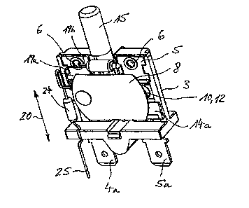
The circuit breaker 1 shown in figures 1 to 3 comprises
a housing base 3, which can be covered by a housing cap
2 and in which a bimetallic connection 4 and a fixed
contact connection 5 are arranged parallel adjacent to
one another. The connections 4 and 5, which are passed
out of the housing base 3 on the connection side with
their connections ends 4a and 5a, respectively, are
fixed within the housing base 3 by means of hollow
rivets 6.
As can be seen in figure 3, the connections 4 and 5 are
in the form of identical flat contacts and are bent
back so as to form a trough 4b, 5b. In the respective
trough apex, the connections 4b, 5b are provided with
openings 7. In the installed state, the openings 7 in
the case of the bimetallic connection 4 are used for
fixing a bimetallic snap-action disk 8 by means of a
rivet 9 and, in the case of the fixed contact
connection 5, are used for accommodating a fixed
contact 10. The bimetallic snap-action disk 8 bears a
bimetallic contact 12 at its contact end 11 facing away
from the bimetallic connection 4. In the installed
state, this bimetallic contact 12 is in the contact-
making, overlapping position with the fixed contact 10
(figure 2).
A two-part isolating slide 13 is arranged between the
bimetallic connection 4 and the fixed contact
CA 02539836 2006-03-31
- 7 -
connection 5 within the housing base 3, which is
expediently made from plastic. Said two-part isolating
slide 13 comprises an L-shaped isolating element 14 and
a pushbutton 15, which is mechanically coupled to said
isolating element 14. A latching or snap-action
connection provided for this purpose is formed by two
latching arms 16, which, in the exemplary embodiment,
are provided on the pushbutton 15 and bear mutually
facing cams 16a on the free-end side. The pushbutton 15
is snapped onto the isolating element 14 by means of
the latching arms 16, in which case the latching cams
16a engage in corresponding latching cutouts 17 in the
isolating element 14. This can be seen relatively
clearly in figure 5.
As shown in a side view of the isolating slide 13 in
figure 4, the pushbutton 15 has a material cutout 18 so
as to form a pushbutton shaft 15a and a pushbutton
section 15b which protrudes beyond said pushbutton
shaft 15a. In the final mounted state, a luminous
element 19, for example a luminaire or a light-emitting
diode, is positioned in said material cutout 18. The
pushbutton 15 is made from a transparent material,
preferably from a transparent plastic.
In each displacement position of the isolating slide
13, which position extends in the direction of the
arrow 20 (figure 4), the luminous element 19 is at
least partially overlapped by the pushbutton section
15b of the pushbutton 15 such that, in any position of
the isolating slide 13, the light emitted by the
luminous element 19 passes to the outside, i.e. to
outside the switch housing 2, 3, via the pushbutton
shaft 15a and/or the pushbutton section 15b of the
pushbutton 15.
The isolating slide 13 has the function of moving
between the two contacts 10, 11 in the event of the
CA 02539836 2006-03-31
- 8 -
circuit breaker 1 having been tripped, for example, by
means of an overcurrent, as a result of which the
contact end 11 with the bimetallic contact 12 moves
away from the fixed contact 10 owing to the bimetallic
snap-action disk 8 opening or bending up. For this
purpose, the isolating slide 13 is spring-loaded with a
spring element 21. The spring element 21 is in this
case supported on one side on the underside 22 of the
isolating element 14, which underside 22 is remote from
the pushbutton 15, and on the other side on the housing
base 3. The electrically insulating isolating function
is taken over by the isolating limb 14a, which extends
transversely with respect to the shaft extent of the
pushbutton 15, of the isolating element 14, which
merges at right angles with the shaft 14b, which bears
the latching cutouts 17, of the isolating element 14.
The isolating element 14 itself is made from a
temperature-resistant plastic material or a plastic
2C material which is resistant to thermal deformation,
preferably from a thermosetting plastic. The reason for
this is the fact that the isolating element 14 is
always at least approximately in touching contact with
the contacts 10, 12 which carry current during
operation.
In the tripping-free ON state of the circuit breaker 1
illustrated in figure 2, the isolating limb 14b of the
isolating element 14 bears against the contacts 10, 12
on the underside, which is remote from the pushbutton
15, of said contacts 10, 12. In the event of tripping,
in the case of which the bimetallic contact 12 is
lifted off from the fixed contact 10 as a result of the
bimetallic snap-action disk 8 bending up or snapping
up, the isolating slide 13 is displaced in the
displacement direction 20 as a result of the spring
force brought about by the spring element 21 and is
guided precisely between the two contacts 10, 12 whilst
CA 02539836 2006-03-31
- 9 -
forming an abutment or stop within the housing base 3.
As a result, the two contacts 10, 12 are mechanically
spaced apart from one another and electrically
insulated from one another.
As a result of this pushing movement of the isolating
slide 13, the pushbutton 15 is displaced by the same
displacement path in the displacement direction 20
owing to the fact that it is coupled with said
isolating element 14, and in the process is guided over
the housing cap 2 towards the outside of the switch
housing 2, 3 through this displacement path. In this
final tripping position of the isolating slide 13, the
pushbutton 15 protrudes beyond a dome-like pushbutton
sleeve 23 placed onto the housing cap 2. This
pushbutton sleeve 23 may be an integral component of
the housing cap 2 or may be snapped onto it as a
separate part.
In the event of tripping, isolation of the contacts 10,
12, owing to the isolating slide 13 pushed between
them, is maintained until the isolating element 14 is
displaced in the opposite direction to the displacement
direction 20 owing to the pushbutton 15 being
depressed. As a result of the spring force of the
bimetallic snap-action disk 8 once it has cooled down,
the bimetallic contact 12 is as a result again pressed
against the fixed contact 10. In this contact-making,
overlapping position, the isolating slide 13 is held in
its initial position in which it has been guided back
and which corresponds to the ON state of the circuit
breaker 1.
In accordance with the wiring for the luminous element
19 which can be seen comparatively clearly in figure 2,
a first connection 19a is passed out of the housing
base 3 via an ohmic resistor 24 so as to form an
external supply connection 25. The supply connection 25
CA 02539836 2006-03-31
- 10 -
is in this case expediently passed out on the same
housing side of the housing base 3, on which the
connection ends 4a, 5a of the connections 4 and 5,
respectively, also lie. The further connection 19b of
the luminous element 19 is guided into the hollow rivet
6, which fixes the bimetallic connection 4 within the
housing base 3, and makes electrical contact with the
bimetallic connection 4 via said hollow rivet 6, for
example makes plugging contact with the hollow rivet 6
or is soldered to it.
With the wiring variant illustrated in the form of a
block diagram in figure 6, in which the luminous
element connection 19a, which is passed to the outside,
is connected, for example, to a neutral conductor of a
power supply system, the luminous element 19 has
current flowing through it in the normal state, i.e. in
the contact-making, overlapping position of the
contacts. With corresponding external wiring, the
pushbutton thus illuminates in the ON state and is not
illuminated in the OFF state when the contacts 10, 12
are open.
In accordance with a further wiring variant shown in
figure 7, the luminous element 19 can also be wired
exclusively within the housing in a manner which is not
illustrated in any more detail. For this purpose, the
connection 19a, which is passed to the outside in
accordance with the variant shown in figures 2 and 6,
of the luminous element 19 is passed in an electrically
contact-making manner into the hollow rivet 6, which
fixes the fixed contact connection 5, in an analogous
manner to the plugging contact-making of the connection
19b. In this case, the luminous element 19 can in turn
be switched on using a series circuit comprising the
nonreactive resistor 24 and the luminous element 19
between the bimetallic connection 4 and the fixed
contact connection 5. In this wiring variant, the
CA 02539836 2006-03-31
- 11 -
luminous element 19 has current flowing through it when
the bimetallic snap-action disk 8 has been tripped,
with the result that the pushbutton 15 is illuminated
in the OFF state and is not illuminated in the ON
state.
With both wiring variants, but in particular with the
wiring variant shown in figures 2 and 6, instead of
open wiring for the luminous element 19 and the
resistor 24, said resistor 24 and the soldered joint
formed between said resistor 24 and the connection 19a
can be covered by shrinkdown tubing (not illustrated).
As a result, undesirable electrical contact-making is
reliably avoided.
The circuit breaker 1 described having an illuminated
pushbutton 15 is suitable for a large number of
application areas, for example as motor, transformer or
cable drum protection.
CA 02539836 2006-03-31
- 12 -
List of references
1 Circuit breaker 21 Spring element
2 Housing cap 22 Underside
3 Housing base 23 Pushbutton sleeve
4 Bimetallic connection 24 Resistor
4a Connection end 25 Connection
4b Trough
Fixed contact connection
5a Connection end
5b Trough
6 Hollow rivet
7 Opening
8 Bimetallic snap-action disk
9 Rivet
Fixed contact
11 Contact end
12 Bimetallic contact
13 Isolating slide
14 Isolating element
14a Isolating limb
14b Shaft
Pushbutton
15a Pushbutton shaft
15b Pushbutton section
16 Latching arm
16a Latching cam
17 Latching cutout
18 Material cutout
19 Luminous element
19a,b Connection
Arrow/displacement direction