Note: Descriptions are shown in the official language in which they were submitted.
CA 02539883 2006-03-16
- 1 -
APPARATUS FOR ESCAPING AREA OF ACCIDENT
FIELD
[0001] The present application relates to apparatus for escaping the area of
an accident and, in particular, to cable-suspended apparatus for emergency
escape from a platform on a rig.
BACKGROUND
[0002] Often it is necessary to have someone working on a rig platform
(such as a derrick tubing board, for example). Sometimes however, rig workers
on such platforms are faced with a blowout or some other kind of accident and
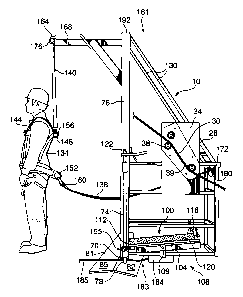
need to escape quickly from the platform in order to avoid being seriously or
fatally injured. Various t-bar or chair-based systems exist for providing a
means
for escaping from such platforms; however a difficulty encountered with known
escape systems is that functionally impaired workers (e.g. workers who are in
a
state of shock as a result of the accident, or workers who have been burned or
disoriented by gases as a result of the accident) can have difficulties in
accessing
and operating them.
[0003] Accordingly, it would be advantageous to improve systems and
devices for escaping accident areas.
SUMMARY OF THE DISCLOSURE
[0004] According to one example embodiment, an apparatus is provided for
emergency escape from a drilling rig platform along a path defined by at least
one cable extending between the platform and a remote, terminal location. The
apparatus includes a frame in which a top of the frame is located above a
bottom
of the frame when the frame is erect. The frame defines an interior space
large
enough to accommodate a worker. A locking system includes a locking
mechanism and also a foot-actuated disengager that is located at least
proximate
to the bottom of the frame. The locking mechanism is adapted to interlock with
a
CA 02539883 2006-03-16
-2-
mating portion on the platform to prevent the frame from travel away from the
platform when the locking mechanism engages the mating portion. The
disengager is connected to the locking mechanism and has a foot receiving
surface region upon which force can be applied to displace the disengager
between a first, engaged position and a second position to disengage the
locking
mechanism from the mating portion. The frame will travel away from the
platform to the terminal location under gravity when the locking mechanism is
disengaged.
[0005] According to another example embodiment there is provided an
apparatus for emergency escape from such a platform along a path defined by at
least one cable extending between the platform and a remote, terminal
location.
The apparatus includes a frame in which a top of the frame is positioned above
a
bottom of the frame when the frame is erect. The frame defines an interior
space
sized to accommodate at least one adult male. A locking means is adapted to
interlock with mating means on the platform to prevent the frame from travel
away from the platform when the locking means engages the mating means. A
foot-actuated disengagement means is located at least proximate the bottom of
the frame and is connected to the locking means. It has a foot receiving
surface
region upon which force can be applied to displace the foot-actuated
disengagement means from a first, engaged position and a second position to
disengage the locking means from the mating means. The frame will travel away
from the platform to the terminal location under gravity when the locking
means
is disengaged.
BRIEF DESCRIPTION OF THE DRAWINGS
[0006] Reference will now be made, by way of example, to the
accompanying drawings which show example embodiments of the present
invention, and in which:
[0007] Figure 1 is a perspective view of a trolley constructed in accordance
with an example embodiment of the invention, the trolley secured in position
next
to a platform;
CA 02539883 2006-03-16
-3-
[0008] Figure 2 is a side elevational view of the trolley of Figure 1;
[0009] Figure 3 is a first end view of the trolley of Figure 1, a worker shown
standing within the trolley; and
[0010] Figure 4 is an opposite end view of the trolley of Figure 1.
[0011] Similar reference numerals may have been used in different figures
to denote similar components.
DESCRIPTION OF EXAMPLE EMBODIMENTS
[0012] Figure 1 illustrates an escape apparatus that includes a trolley 10
that is secured in position next to a platform 18 and, in particular, next to
an
egress 14 defined by the platform 18. In at least some embodiments, the
platform 18 is at an elevated location on a rig of the type used for drilling
or
servicing of wells, for example. It will be understood that workers carrying
out
tasks in relation to the drilling or servicing operation are able to stand on
floor 22
of the platform 18 in order to carry out work at the location of the platform
18.
Extending vertically upwards from the floor 22 are a plurality of posts 17.
Extending between top ends of the posts 17 are handrails 19 which can be
grasped by a rig worker. The platform shown in Figure 1 is a derrick tubing
board; however those skilled in the art will appreciate that at least some
example
embodiments of the escape apparatus disclosed herein are suitable for use in
conjunction with other types of platforms such as a racking board, for
example.
Although the egress 14 shown in Figure 1 is located at the rear center of the
platform 18, in some example embodiments the egress will be located at a
different location, such as either rear corner, for example.
[0013] The trolley 10 is a rigid structure designed for providing a vehicle
for
a rig worker to escape from the platform 18 in the case of an accident such as
a
blowout or the like. In at least some embodiments, the trolley 10 comprises a
metal frame 26 composed of a plurality of metal members that define an
interior
space of the trolley 10 to accommodate one or more workers. As will be
CA 02539883 2006-03-16
-4-
appreciated by those skilled in the art, adjacent metal members of the frame
26
can be attached to each other by suitable means such as by welding or bolting,
for example. One or more metal members may be liftable or removable. For
instance, an optional liftable or removable bar 29 (Figure 4) can be moved out
of
the way when a worker 134 enters or exits the trolley 10, and then put back in
place once he has entered or exited as the case may be. Alternative
displaceable
barriers to the illustrated removable bar 29 are contemplated. For example,
two
short bars hingedly attached and perpendicularly extending out from opposite
sides of the egress 14 could be employed. These two bars would be attached to
the frame 26 at roughly the same height and would each extend out slightly
less
than half the distance across the egress 14. Furthermore, the two bars would
swing inwardly once pressed upon by a worker entering the trolley 10 through
the
egress 14.
[0014] In some example embodiments, the frame 26 is made of aluminum,
and in some examples the trolley 10 weighs between 80 and 120 kgs. In some
examples, known bonding means can be implemented to reduce the ability of the
frame 26 to act as a transmitter of static electric charge. Also, although the
trolley 10 will typically be a metal trolley, it will be understood that the
trolley
could at least in part be made of some other material such as graphite, for
example. Although not illustrated, in some examples the trolley 10 includes
one
or more vertical walls/barriers which, for example, can serve to keep the
hands or
feet of a rig worker inside the trolley 10.
[0015] A rig worker standing on the floor 22 of the platform 18 can enter
the trolley 10 by exiting the platform 18 through the egress 14 to enter the
interior space of the trolley 10. This interior space is at least sufficiently
large to
accommodate one worker; however in some examples the interior space is
sufficiently large to accommodate two or more people. Because in at least some
embodiments it is acceptable if the head of the rig worker sticks out above
the
top boundary of the interior space defined by the trolley frame, it will be
understood that the upper metal members of the trolley frame need not
necessarily be a particular minimum height above the base of the frame. For
instance, the illustrated frame 26 defines an interior space that will
accommodate
CA 02539883 2006-03-16
-5-
the worker 134 even though his head will stick out above upper metal members
130 of the frame 26.
[0016] To protect a rig worker from an accidental fall off of a rig platform,
it
is typical for a number of lanyards to be employed wherein one end of each of
the
lanyards is connected to the worker, and the other end of each of the lanyards
is
connected to the rig platform upon which the worker intends to carry out work.
In the illustrated setup, two similar purpose lanyards are employed: a lanyard
138 (sometimes referred to as the working lanyard) and a lanyard 140
(sometimes referred to as the overhead fall arrest). It will be understood
that in
the conventional case where the rig worker needs to escape from the platform,
the worker would need to disconnect lanyards that would otherwise prevent the
rig worker from distancing himself from the platform. The disconnection steps
that the worker would need to take would add to the duration of the time it
takes
the worker to escape, as well as the complexity of the escape process for the
worker.
[0017] Referring for instance to the example embodiment illustrated in
Figure 2, the lanyards 138 and 140 are connected to the escape apparatus 10
rather than the platform 18. The impact of this modified setup is that a rig
worker in an accident situation does not need to spend time and effort
disconnecting any of the previously described lanyards as there are no
lanyards
connecting the worker to the platform 18. A further impact of the illustrated
setup is that the rig worker saves additional time that would normally be
taken in
connecting one or more lanyards extending between himself and the escape
apparatus (because one or more lanyards are already so connected). Thus the
lanyards 140 and 138 are multi-purpose. Firstly, when the rig worker is
standing
on the floor 22 of the platform 18, the lanyards 138 and 140 prevent an
accidental free fall off of the platform 18. Secondly, when the rig worker is
within
the trolley 10, the lanyards 138 and 140 prevent an accidental free fall out
of the
trolley 10. Also, it will be understood that although lanyards are the linking
means shown in Figures 2, 3 and 4, other suitable linking means are possible
such as non-lanyard ropes, cables, chains or any suitable combination or
splicing
of linking means.
CA 02539883 2006-03-16
-6-
[0018] In a number of exemplary embodiments, shackles 156 and 160 at
ends of the lanyards attach to a set of belts 144 at rings 148 and 152
respectively
(these rings hang off of the set of belts 144) while the other ends of the
lanyards
140 and 138 are respectively attached at jutting end 164 of overhang member
168 and at a frame location 172 at the back of the trolley 10. As seen in
Figure
2, for example, the overhang member 168 is adapted to extend into the region
of
the platform 18 when the trolley 10 is positioned next to the platform 18 so
that
the end 164 of the overhang member 168 is close to any rig worker who might be
standing on the floor 22 of the platform 18. Alternative points of attachment
for
the end of the lanyard 140 are possible. If there is no overhang member 168,
attachment of the lanyard end can be, for example, at frame apex 192 (Figure
2).
Reels 176 and 180 are used to vary the slack of the lanyards 140 and 138. It
will be understood that the reels 176 and 180 are optional. In the example
embodiment illustrated in Figure 3, for instance, there is a shackle 179 at
frame-
connecting end of the lanyard 138 (instead of the reel 180).
[0019] During its descent down and away from the platform 18, the trolley
moves away from a start location at the platform 18 that is associated with
worker loading, to a terminal location associated with worker unloading by
travel
along at least one path-defining cable. In the example embodiment illustrated
in
Figure 1, there are two path-defining cables 30; however the number of cables
used may vary. For example, in some example embodiments four, three or even
only one cable might be used. In some example embodiments, the use of more
than one cable may permit a more stabilized descent and may simplify setup and
locking of the trolley against the platform at the time the trolley is brought
to the
start position and made available to be used when needed. In at least one
example, the cables used are ;1'
6,- diameter steel cables.
[0020] As can be seen in Figure 1, one end of each of the cables 30 are
hooked up to the platform 18. In at least some examples, this upper point of
attachment is several feet above the floor 22. The other ends of the cables 30
are anchored with ground anchors 33 (Figure 1) to the ground at a location
safely
distant from the platform 18, for instance at location 32 which in some
examples
is horizontally distanced about 80 to 100 feet from the platform 18. In some
CA 02539883 2006-03-16
-7-
examples, the ground anchors 33 are screwed in anchors that have been pull
tested. In at least one alternative example, a portable anchor secured by the
weight of a vehicle is used instead of a ground anchor.
[0021] The illustrated trolley 10 includes a pair of pulley assemblies 34 for
cammed movement. In the Figures, the pulley assemblies 34 are mounted and
attached on the sides of the frame 26 at a height between top 181 and bottom
183 of the frame 26, thereby permitting the centre of gravity of any worker
riding
in the trolley 10 to be below the pulley assemblies 34. In Figure 2, one of
the
pulley assemblies 34 is shown with sheave cover 36 removed. As shown in this
figure, each of the pulley assemblies 34 includes two sheaves 38 and 39, each
having a peripheral surface in contact with one of the cables 30. It will be
understood that alternative examples wherein a different number of sheaves are
employed is contemplated. Furthermore, although in the illustrated example
embodiment the cable 30 passes directly over the top of the sheave 38 and
directly under the bottom of the sheave 39, those skilled in the art will
appreciate
that other cable engagement configurations are possible.
[0022] It will be understood that the trolley 10 could be brought up from
the ground to the start location at the platform 18 by one of a number of
different methods. If the trolley 10 is brought to the terminal location and
put
onto the cables 30, a winch (not illustrated) could be used to pull the
trolley 10
up to the start location. Alternatively, a conventional crane or some other
suitable lifting device could be used to lift the trolley to the start
location at the
platform 18.
[0023] Once the trolley 10 is brought up against the platform 18, a
releasable locking system is employed to hold the trolley 10 in position
against
the platform 18, until the trolley is required for lowering a worker from the
platform. A locking system in accordance with at least one example embodiment
is best illustrated in Figure 2. Locking mechanism 155 of the illustrated
locking
system includes a locking pin 70 at a lower end of a rod 74 that is vertically
displaceable and located adjacent an upright frame member 76 of the frame 26.
Once positioned over locking pin hole 78, the pin 70 is dropped into and
extends
through locking the pin hole 78 defined in locking plate 82. It will be
understood
CA 02539883 2006-03-16
-8-
that the weight of the rod 74 and lateral forces caused by gravitational
influence
on the trolley 10 help maintain the position of the locking pin 70 within the
locking pin hole 78. Optionally, a latch or some other releasable locking
mechanism could be used to further ensure that the locking pin 70 is kept in
the
locking position. For example, a latch could be used to restrict vertical
displacement of the rod 74 when the trolley 10 is not being used. In some
example embodiments, more than one vertically displaceable rod is employed.
For instance, in one example embodiment there is a second rod adjacent the
other of the two vertically extending frame members at the entrance/exit
trolley
end. In such an example embodiment there would be two locking pin holes in the
locking plate 82, each receiving one locking pin.
[0024] Although a locking pin hole is the mating portion on the platform 18
of the illustrated example embodiment, it will be understood that other
arrangements of mating parts are contemplated. For example, the mating
portion on the platform 18 could be a male mating part rather than a female
mating part. It will be appreciated that one skilled in the art would be able
to
carry out this type of a modification without undue effort, and that such a
modification would not in and of itself have a material effect on the way the
locking system works:
[0025] The locking plate 82 is joined to an adjacent plate 85 by suitable
means such as by welding, for example. (Alternatively, the plates 82 and 85
could, for example, be a single plate bent along edge 81.) The illustrated
locking
plate 82 is downwardly angled from the adjacent plate 85; however in some
examples the locking plate 82 could extend out horizontally instead of being
downwardly angled. Also, in some examples the locking plate 82 could be a
hinged plate (e.g. hinged along the edge 81). An impact of employing a hinged
plate would be the ability to vary the angle of the locking plate depending
upon
the trolley employed and also the angle of trolley descent from the start
location
at the platform. In some example embodiments, the plate 85 is attached to
beam 83 of the platform 18 (Figure 1) during assembly of the platform 18.
[0026] In at least a number of example embodiments, the locking system of
the escape apparatus includes a foot-actuated disengager for releasing the
frame
CA 02539883 2006-03-16
-9-
26 of the escape apparatus from a locked state so that the frame 26 is free to
descend down and away from the platform 18 under the influence of gravity. The
foot-actuated disengager that is illustrated is a pivoting plate disengager
100.
This disengager 100 includes a rectangular frame 104, two sides of which are
attached to floor section 108 at hinge 109 (at a bottom of the frame 26). In
at
least one example, the hinge attachment is at least relatively close to the
midpoint between ends 112 and 116 of the disengager 100. Attachment as
shown is analogous to the attachment of a beam to a centre support when a
playground seesaw is assembled.
[0027] The disengager 100 also includes a plate 120 attached to its frame
104 and adapted to be stood upon (or stepped on) by a rig worker after he
enters
into the trolley 10. The illustrated disengager 100 is such that when no
weight is
placed on the plate 120, the end 116 is in a raised position relative to the
end
112 (i.e. the end 116 is higher than the end 112). Conversely, when a rig
worker
stands on a foot receiving surface region of the plate 120 sufficiently close
to the
end 116, the weight applied by the worker downwardly on the disengager 100
causes the end 116 to descend while the end 112 rises in a manner analogous to
the motion of a seesaw.
[0028] The rod 74 is (in a number of examples) hooked onto the disengager
100 at a location proximate to the end 112. In some alternative examples, the
rod 74 is rigidly linked to the end 112 in some other manner than being
hooked.
For instance, a vice-type gripping mechanism could be employed. Because the
end 112 is rigidly linked to the rod 74, when the end 112 is caused to rise by
the
rig worker standing on the plate 120, so too is the rod 74 caused to rise.
Because the pin 70 is integral (or alternatively rigidly linked in some other
manner) to the rod 74, the pin 70 undergoes the same upward movement that
occurs in relation to the rod 74. Removal of the locking pin 70 from the
locking
pin hole 78 is effected by upward movement of the pin 70. Thus, it will be
understood that the locking pin 70 is moved in or out of locking position by
lowering or raising (respectively) of the rod 74. Also, the rod 74 can be
raised by
pulling on it by means of an optional handle 122, or without the use of the
handle
122 by gripping on the shaft of the rod 74 itself.
CA 02539883 2006-03-16
-10-
[0029] When the locking pin 70 has risen out of the locking pin hole 78, the
locking mechanism 155 is disengaged from the mating portion and the trolley 10
is free to travel down and away from the platform 18 under the influence of
gravity. In at least some embodiments, one or more braking devices are used to
prevent the falling trolley from entering a rapid, uncontrolled descent.
Referring
for instance to the example embodiment illustrated in Figure 1, an automatic
braking device 184 is attached at the bottom of the trolley 10, beneath the
disengager 100. In at least one example, as the trolley 10 descends the
braking
device 184 gradually lets out length of a cable lanyard 185 anchored to the
underside of the floor 22 of the platform 18. Descent can be quick but still
slowed down to prevent an excessively forceful impact when the trolley 10
arrives
at the ground or other terminal location.
[0030] In at least one example, the braking device 184 that is employed is
the Rollgliss Rescue Emergency Descent Device model no. 3303001, which is
manufactured by DBI/SALA & Protecta. For sloped descent applications, a half
inch diameter guide cable is normally used in conjunction with the Rollgliss R
device; however this guide cable is not needed for the sloped descent
application
herein disclosed because the trolley 10 is suitably guided by the cables 30
that
extend between the platform 18 and the terminal location 32. Using the
Rollgliss R device, a controlled descent rate of 15 feet/second or greater can
be
achieved. If the Rollgliss device is employed, it will dictate the weight
capacity
of the trolley 10. For example, if the Rollgliss device is rated to support
up to
230 kgs, and if, for example, the trolley 10 weighs 105 kgs, then the
recommended maximum amount of person and cargo weight for loading into the
trolley 10 would be 125 kgs. It will be understood that in some examples
weight
capacity of the trolley will be dictated by some other factor or factors
besides the
weight rating for the braking device 184. For instance, in at least one
example
the weight capacity of the trolley will be limited by the strength of the
anchoring
at the terminal location 32.
[0031] It will be understood that alternative braking systems besides those
employing the illustrated braking device 184 are contemplated. For example,
known braking systems that employ hand actuated levers (including those for
CA 02539883 2006-03-16
- 11 -
overriding automatic braking settings) are contemplated. Also, one skilled in
the
art will appreciate that the braking device 184 need not be attached at the
bottom of the trolley 10, but could be attached at a higher location; however
attachment of the braking device 184 to the top of the trolley 10, for
example,
could have the effect of making the trolley 10 more top heavy.
[0032] In some examples, lighting will be provided at the egress 14 and/or
the terminal location 32. This lighting may improve visibility for the
escaping
worker, especially when the escape apparatus is used during non-daylight
hours.
[0033] Certain adaptations and modifications of the described embodiments
can be made. Therefore, the above discussed embodiments are considered to be
illustrative and not restrictive.