Note: Descriptions are shown in the official language in which they were submitted.
CA 02540597 2006-03-21
BATTERY CHARGING ASSEMBLY FOR USE ON A LOCOMOTIVE
TECHNICAL FIELD
[0001 ] The present invention relates to a battery charging assembly for use
on a
locomotive, and more specifically, to a battery charging assembly which
provides an
electrical power output which is operable to, on the one hand, maintain the
electrical
charge of batteries, which are utilized on the locomotive, and further, can be
employed
to energize electrical devices for remotely controlling the operation of the
locomotive.
BACKGROUND OF THE INVENTION
[0002] The prior art is replete with numerous examples of devices which employ
schemes for charging the batteries which might be utilized on a locomotive.
For
example, in U.S. Patent No. 6,236,185 a compressed air power supply and
rechargeable battery pack is described. In this arrangement, an air powered
electrical
generator is utilized to recharge a battery which provides peak operating
power as well
as backup power for electrical devices in End of Train (EOT) arrangements if
the
generating system is subsequently rendered inoperable. Still further, in U.S.
Patent
No. 6,308,639 a hybrid battery/gas turbine locomotive is described. A
microturbine
which produces as much as much as 80 kW of electrical power is utilized to
charge a
large number of batteries which are utilized to power the locomotive. The
microturbine
that is described has a charging power between 25 and 250 kW. The arrangement,
as
shown in this patent is adapted for use on a locomotive which is used as a
switching
vehicle.
K1110091 P01. doc 1
CA 02540597 2006-03-21
[003] Another relevant prior art reference is U.S. Patent No. 4,087,734 to
Blutreich and which relates to a charging circuit for a combination trolley
and battery
powered locomotive. In this U.S. Patent, there is disclosed an electrical
charging circuit
for charging the locomotive battery from the voltage of a trolley wire. This
arrangement
includes a contactor device which is provided in the circuit between the
trolley wire and
the battery. In the disclosed arrangement the contactor device is energized to
supply
direct current power from the trolley wire to the battery to permit charging
of the battery
to a preselected voltage level. A voltage sensing apparatus is provided in the
circuit
between the contactor and the battery, which monitors the voltage level of the
contactor
device. The battery power is provided to the locomotive, or trolley when
electrical
power is not available from an overhead trolley wire.
[0004] U.S. Patent No. 6,725,134 relates to a control strategy for diesel
engines
and auxiliary loads to reduce emissions during engine power level changes. In
this
invention, a control system is provided which monitors, screens, and
prioritizes the
application of additional auxiliary loads, and when possible, defers the
application until
the load increase demanded on the engine due to the throttle position changes
has
been satisfied, that is, the engine has reached steady-state operation at the
new load
level. The prioritization scheme is based on the operating conditions of the
engine, and
specific auxiliary load requesting activation. In this arrangement, if
operating conditions
do not permit deferral of the additional auxiliary load, then the auxiliary
loads are
sequentially switched on and off to avoid a situation where several auxiliary
loads
simultaneously demand additional power from the diesel engine.
K1 110b91 P01. doc 2
CA 02540597 2006-03-21
[0005] A battery charging assembly which addresses the various shortcomings
attendant with the prior art devices and practices utilized heretofore is the
subject matter
of the present invention.
SUMMARY OF THE INVENTION
[0006] A first aspect of the present invention relates to a battery charging
assembly for use on a locomotive and which includes a diesel engine having a
mechanical power output of less than about 50 horsepower; an oil tank coupled
in fluid
flowing relation relative to the diesel engine, and which contains a volume of
oil which
facilitates the operation of the diesel engine for a time period which is at
least equal to a
maintenance interval for the locomotive; and an alternator coupled to the
mechanical
output of the diesel engine, and which produces an electrical power output to
charge a
plurality of batteries which are mounted on the locomotive.
[0007] Another aspect of the present invention relates to a battery charging
assembly for use on a locomotive and which includes an oil tank which is
mounted on
the locomotive and which has a top surface, and which further encloses a
volume of oil;
a diesel engine of less than about 50 horsepower, and which is mounted on the
top
surface of the oil tank, and which is further coupled in fluid flowing
relation relative to the
oil tank, and wherein the diesel engine, when actuated, produces a mechanical
power
output, and is further operable to withdraw oil from oil tank, and return the
oil to the oil
tank following the circulation of the oil in the diesel engine; a selectively
engageable
clutch which is mounted in force receiving relation relative to the mechanical
power
output of the diesel engine; an air compressor mounted on the top surface of
the oil tank
and which mechanically cooperates with the clutch, and wherein the clutch,
when
KI 110091 P01. doc
CA 02540597 2006-03-21
engaged, is operable to deliver mechanical energy from the diesel motor to
actuate the
air compressor, and wherein the air compressor, when actuated, provides a
source of
compressed air which is delivered to the locomotive; an alternator, mounted on
the oil
tank, and which is coupled in force receiving relation relative to the
mechanical power
output of the diesel engine, and wherein the alternator, when actuated by the
diesel
engine, provides a DC electrical power output of less than about 74 volts DC
to charge
a plurality of batteries which are mounted on the locomotive; and a
programmable
controller which is coupled in controlling relation relative to the diesel
engine, and the
clutch, and which further controls, at least in part, the operation of the
alternator and the
air compressor.
[0008] Still another aspect of the present invention relates to battery
charging
assembly for use on a locomotive and which includes an oil tank defined by a
top and
bottom surface, and a sidewall which extends between the top and bottom
surfaces,
and wherein the oil tank is mounted on, and disposed in spaced relation
relative to, the
locomotive, and wherein the oil tank defines an internal cavity having
opposite first and
second ends, and which receives and stores a volume of oil which is greater
than about
15 gallons therein, or of a volume which will allow the diesel engine to
operate for at
least 92 days, and wherein an oil diffusing baffle is positioned within the
cavity of the oil
tank and is disposed in spaced relation relative to the top surface thereof,
and wherein
an aperture is formed in the top surface and which facilitates access to the
cavity; a
diesel engine of less than about 50 horsepower and which is mounted on the top
surface of the oil tank, and which is further coupled in fluid flowing
relation relative to the
oil tank by way of the aperture which is formed in the top surface, and
wherein the
diesel engine, when actuated, has a mechanical power output, and further
withdraws oil
KI 1 t 0091 P01. doc 4
CA 02540597 2006-03-21
from the oil tank, and then, following circulation in the diesel engine,
returns the
previously withdrawn oil back into the oil tank and onto the oil diffusing
baffle, and
wherein the oil diffusing baffle directs the oil along a path of travel and
delivers the oil to
a location which is near the opposite ends of the cavity to facilitate the
mixing of the oil
within the cavity; a fuel line coupled to the diesel engine and having a
distal end which
is received within a diesel fuel tank, and which is mounted on the locomotive,
and which
is further positioned remotely relative to the diesel engine, and wherein the
diesel
engine withdraws a source of diesel fuel from the diesel fuel tank and through
the fuel
line for consumption; a starting battery borne by the top surface of the oil
tank, and
which provides an electrical current; a starting motor coupled in force
transmitting
relation relative to the diesel motor and which is selectively energized by
the electrical
current which is provided by the starting battery, and wherein the starting
motor, when
energized renders the diesel engine operational; a cooling radiator coupled in
fluid
flowing relation relative to the diesel engine, and which cools the diesel
motor after the
diesel engine has been started; a selectively engageable clutch which is
mounted in
force receiving relation relative to the mechanical power output of the diesel
engine; an
alternator which is coupled in force receiving relation relative to the
mechanical power
output of the diesel engine, and wherein the alternator, when actuated,
produces an
electrical power output of less than about 74 volts DC which is utilized, at
least in part,
to charge a plurality of batteries which are mounted on, and subsequently
utilized by the
locomotive, to provide electrical power for the controls and the occasional
propulsion of
the locomotive; a DC to DC converter which is electrically coupled to the DC
electrical
power output of the alternator, and which provides a charging current for
maintaining
the electrical charge of the starting battery; an air compressor borne by the
top surface
KI110091P01. doc
CA 02540597 2006-03-21
of the oil tank and which is disposed in selective force receiving relation
relative to the
diesel engine by the clutch, and wherein the air compressor, when actuated,
provides a
source of compressed air which is delivered to the locomotive and selectively
utilized by
the locomotive for braking and other needs; and a programmable controller
which is
coupled in electrical charge sensing relation relative to the plurality of
batteries which
are mounted on the locomotive, and further disposed in controlling relation
relative to
the diesel engine, the starting motor for the diesel motor, the alternator,
the air
compressor and the selectively engageable clutch.
[0009] These and other aspects of the present invention will be discussed in
greater detail hereinafter.
BRIEF DESCRIPTION OF THE DRAWINGS
[0010] Preferred embodiments of the invention are described below with
reference to the following accompanying drawings.
[0011 ] Fig. 1 is a greatly simplified depiction of the present invention as
it would
be deployed and utilized on a remotely controlled locomotive which is operably
coupled
with a second locomotive.
[0012] Fig. 2 is a perspective, side elevation view of an oil tank which is
utilized
with the present invention.
[0013] Fig. 3 is a perspective, exploded, side elevation view of the oil tank
of
Fig. 2.
[0014] Fig. 4 is a perspective, side elevation view of the battery charging
assembly of the present invention.
K1110091 P01. doc
CA 02540597 2006-03-21
[0015] Fig. 5 is a perspective, exploded view of an oil delivery tube which is
utilized with the present invention.
[0016] Fig. 6 is a plan view taken through an aperture which is defined by the
oil
tank as seen in Fig. 2.
[0017] Fig. 7 is a perspective view of a control assembly including a
programmable controller which is utilized with the present invention.
[0018] Fig. 8 is a side elevation view of a vibration isolating assembly which
is
utilized with the present invention.
[0019] Fig. 9 is a fragmentary view of a fuel line which is employed with the
present invention.
DETAILED DESCRIPTION OF THE PREFERRED EMBODIMENTS
[0020] This disclosure of the invention is submitted in furtherance of the
constitutional purposes of the U.S. Patent Laws "to promote the progress of
science and
useful arts" (Article 1, Section 8).
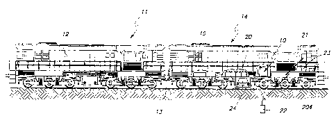
[0021 ] A battery charging assembly for use on a locomotive is generally
indicated
by the numeral 10 in Fig. 1 and 4 respectively. As seen in Fig. 1, a first
diesel powered
locomotive 11 of conventional design is illustrated. A diesel engine 12 which
is provided
on the locomotive 11 is operable to drive an electrical generating system (not
shown)
and which, in turn, supplies electrical current to a plurality of direct
current, or alternating
current traction motors having rotors which are drivingly coupled, through
speed
reducing gearing, to axle-wheel sets of the locomotive. In the arrangement as
shown,
the locomotive 12 is coupled through a controlling coupler 13 to a remotely
controlled
locomotive 14 and which is mechanically coupled thereto. This controlling
coupler 13 is
KI 110091 P01. doc 7
CA 02540597 2006-03-21
familiar to those who are skilled in the art, and allows the diesel locomotive
11 to be
controlled by way of the remotely controlled locomotive 14. The remotely
controlled
locomotive 14 includes, among other things, at least one traction motor 15
which
supplies a mechanical output which drives the wheels of the locomotive when
the
locomotive 14 is occasionally detached from the locomotive 11. The locomotive
14
does not have a large horse power diesel motor mounted thereon and which would
typically drive the locomotive 14. However, in those instances where the
remotely
controlled locomotive 14 is separated from the diesel locomotive 11 as might
be
occasioned when the diesel locomotive 11 has become disabled, the traction
motor 15
is supplied with electrical power to drive the locomotive 14 by way of a
plurality of
c
batteries 20 which are positioned or mounted on the remotely controlled
locomotive 14.
In the arrangement as seen in Fig. 1, the remotely controlled locomotive 14
has
mounted thereon an electrically actuated control assembly 21 which is operated
remotely by a wireless control 22. By means of the wireless control, a remote
operator
can operate the diesel locomotive 11 and the remotely controlled locomotive 14
and
utilize same to switch railroad cars, and do other tasks without the need for
a locomotive
engineer being present. The remotely controlled locomotive further has an air
brake
compartment 23 having conventional air brake components. As should be
understood,
the remotely controlled locomotive 14 when separated from the diesel powered
locomotive, and being propelled by the traction motor 15, uses compressed air
for
braking the locomotive while it is traveling alone and other purposes.
Otherwise, when
controllably coupled to the diesel locomotive 11, the diesel locomotive 11
typically
provides compressed air for braking to the locomotive 14. The remotely
controlled
locomotive 14 further has a diesel fuel tank 24 which encloses a source of
diesel fuel.
K1110091 PO1. doc $
CA 02540597 2006-03-21
[0022] Referring now to Fig. 8, the battery charging assembly for use on a
locomotive 10 of the present invention is mounted in spaced relationship
relative to a
supporting surface of the remotely controlled locomotive 14 by way of a
plurality of
vibration isolating mounting fixtures, one of which is seen in Fig. 8. The
vibration
isolating mounting fixtures 30 include a base plate 31, which is affixed by
welding, to an
underlying supporting surface. The base plate 31 which is typically fabricated
from
steel, or the like, has a bottom surface 32 which rests in juxtaposed relation
relative to
an underlying supporting surface. Further, the base plate includes opposite
top surface
which has attached thereto a circumscribing upwardly extending wall 33. An
internal
cavity 34 is defined by the circumscribing wall. Still further, a shaft 35 is
affixed at one
end to the base plate 31 and extends normally upwardly relative thereto and
terminates
in a threaded end portion 40. As seen in Fig. 8, a plurality of substantially
annularly
shaped synthetic, and resilient members 41 are received about the shaft 35.
Still
further, a metal washer 42 is received about the shaft 35 and is operable to
retain the
plurality of resilient members 41 thereon. A lock washer 43 is operable to
engage the
metal washer 42, and further, a nut 44 of conventional design is operable to
threadably
mate with the threaded end portion 40 thereby capturing the plurality of
resilient
members 41 on the shaft 35. The vibration isolating mounting fixture is
operable to
minimize the amount of vibration which is transmitted between the remotely
controlled
locomotive 14, and the battery charging assembly 10.
[0023] Referring now to Figs. 2 and 3, the battery charging assembly for use
in a
locomotive 10 includes an oil tank 50 which encloses a volume of oil which is
utilized in
the battery charging assembly 10. The volume of oil selected would be at least
equal to
the amount needed to run the battery charger during the maintenance interval
for the
KI110091 P01. doc
CA 02540597 2006-03-21
remotely controlled locomotive 14. This amount of oil would be generally
greater than
about 15 gallons. The relatively large oil tank was selected to allow the
present battery
charging assembly 10 to be versatile, and to minimize maintenance of the
battery
charging assembly to only those occasions when the remotely controlled
locomotive
may be being serviced for other reasons. The oil tank 50, as seen in Fig. 3
has a base
portion which is generally indicated by the numeral 51. The base portion is
defined by a
bottom wall 52 which has a first end 53 and an opposite second end 54.
Extending
substantially normally upwardly relative to the first and second ends is a
first end wall 55
and a second end wall 56.
[0024] As seen most clearly in Fig. 4 a conventional oil drain valve 57 is
mounted
on the second end wall 56 and facilitates the draining of oil from the oil
tank 50. Still
further, a conventional oil-sight level gauge 58 is mounted on the second end
wall 56
and facilitates an operator's determination of the amount of oil that is in
the oil tank. As
seen in Fig. 3, suitable apertures 59 are formed in the second end wall so as
to couple
the oil drain valve and oil-sight level gauge in fluid flowing relation
relative to the oil tank.
[0025] As seen in Fig. 3, lifting fixtures 60 are mounted to the opposite ends
of
each of the first and second end walls 55 and 56, respectively. Each lifting
fixture 60
has an aperture 61 formed therein, and which facilitates the attachment of a
suitable
lifting device in order to facilitate the movement of the present battery
charging
assembly 10 using conventional lifting devices, and place it in an appropriate
position
within the remotely controlled locomotive 14. Still further, and as seen in
Fig. 3,
mounting plates 62 are individually affixed to both the individual lifting
fixtures 60, and to
the bottom wall 52. Each of these mounting plates have an aperture 63 formed
therein,
and which are operable to receive the threaded end portion 40 of the shaft 35
and a
KI 110091 P01. doc 1 0
CA 02540597 2006-03-21
portion of the resilient and synthetic members 41 previously described, and
which forms
a portion of the vibration isolating mounting fixture 30 as seen in Fig. 8. As
will be
understood, therefore, at least four vibration isolating mounting fixtures 30
are
individually mounted in the respective corners of the base portion 51 thereby
securing
the bottom wall 52 in spaced relation relative to an underlying supporting
surface 65 of
the remotely controlled locomotive 14.
[0026] Referring now to Fig. 3, it should be understood that the oil tank 50
defines an internal cavity 64 which contains the volume of oil necessary for
the battery
charging assembly 10 to effectively operate between maintenance cycles of the
remotely controlled locomotive 14. Positioned within the internal cavity 64 is
an oil
diffusing baffle 70 which is operable to facilitate the mixing of the oil
which is enclosed
within the internal cavity 64. In this regard, the oil diffusing baffle 70 has
a main body
71 which has a first sloped portion 72, and a second sloped portion 73. As
illustrated in
Fig. 3, the first and second sloped portions are joined at an apex 74. Each of
the first
and second sloped portions have a top surface 80. Yet further, an aperture 81
is
formed in each of the top surfaces of the first and second sloped portions 72
and 73 and
is positioned at substantially the apex thereof. As illustrated in Fig. 3, a
transversely
disposed support member 82 is positioned therebelow the first and second
sloped
portions 72 and 73 and is operable to support same as well as being disposed
in rested
relation on the bottom wall 52. Yet further, it will be seen in Fig. 3 that a
pair of
longitudinally disposed support members 83 are individually affixed to each of
the first
and second sloped portions 72 and 73. These respective support members 83 are
utilized to direct oil which is being delivered back into the oil tank 50
along a course of
travel where the oil travels along the top surface 80 of the individual first
and second
K1110091 P01. doc 1 1
CA 02540597 2006-03-21
sloped portions, and is thereafter deposited at a location near the first and
second ends
53 and 54, respectively of the bottom wall 52. As seen the exploded view of
Fig. 3, the
oil diffusing baffle defines a number of oil passageways 84 which are formed
therein
and which facilitate the movement of the oil throughout the oil tank 50 and
result in the
efficient mixing thereof.
[0027] Referring still to Fig. 3, the oil tank 50, which is utilized with the
present
invention, has a top portion generally indicated by the numeral 90. The top
portion
includes an upwardly facing surface 91 which has a first end 92, and an
opposite
second end 93. Still further, the upwardly facing surface 91 has opposite
peripheral
edges 94 and 95, respectively. Affixed to and depending substantially normally
downwardly relative to the opposite peripheral edges 94 are individual first
and second
sidewalls 96 and 97 respectively. These opposite sidewalls are operable to be
received
therebetween the first and second end walls 55 and 56, and are further secured
thereto
by means of welding and the like to make a substantially fluid impervious
container. As
seen by reference to Fig. 3, the oil diffusing baffle 90 is positioned
therebetween the first
and second sidewalls 96 and 97 and in the internal cavity 64 of the oil tank
50.
[0028] Referring now to Figs. 2 and 3, it will be seen that a support member
100
extends substantially normally upwardly relative to the upwardly facing
surface 91 and
is positioned adjacent to one of the peripheral edges 95. The support member
has a
plurality of apertures 101 formed therein and various components of the
battery
charging assembly 10 of the present invention are mounted thereto, and which
will be
discussed in greater detail hereinafter. Closely adjacent to the second end 93
of the
upwardly facing surface 91 is an oil filling aperture 102. As will be
discussed below, the
oil filling aperture allows a given volume of oil to be received in the oil
tank 50 when the
K1110091 P01. doc 12
CA 02540597 2006-03-21
battery charging assembly 10 of the present invention is operational. Mounted
adjacent
to the oil filling aperture 102 is a compressor mount 104. The compressor
mount is
affixed by welding, and the like, to the upwardly facing surface 91, and is
positioned
near the second end 93. Positioned near the first end 92 of the upwardly
facing
surface, and positioned adjacent one of the peripheral edges 95 is an
alternator mount
105. Still further, a battery mount 106, of conventional design, is affixed
near the
second end 93 and is adjacent to the alternator mount 105.
[0029] Positioned generally centrally relative to the upwardly facing surface
91 is
an engine mount 110. The engine mount is defined by an upwardly extending
sidewall
111 which is affixed by welding and the like to the upwardly facing surface
91. A
mounting flange 112 is affixed by welding to the upwardly extending sidewall
111 and
has a plurality of apertures 113 formed therein as seen most clearly by
reference to
Fig. 5. As best illustrated by reference to Fig. 6, the engine mount 110
defines a
passageway 114 which allows fluid communication between the oil tank 50, and
the oil
received in same, and a diesel engine, which will be discussed below, and
which is
affixed to the engine mount 110. As illustrated in Fig. 6, it will be seen
that the oil
diffusing baffle 70 is positioned in spaced relation relative to the top
portion 90 thereby
allowing oil to travel along the top surface 80 thereof.
[0030] Referring now to Fig. 4, it will be seen that the battery charging
assembly
of the present invention includes a diesel engine 120 of conventional design
and
which has a mechanical power output of less than about 50 horsepower. As shown
herein, the diesel motor which is depicted has a mechanical power output of
less than
about 20 horsepower. The diesel engine 120 is mounted onto the engine mount
110
using conventional fasteners which pass through the apertures 113 which are
formed in
KI110091POt.doc 13
CA 02540597 2006-03-21
the mounting flange 112. The diesel engine 120 is supplied with diesel fuel
from the
diesel fuel tank 24 which is positioned on the remotely controlled locomotive
14 as seen
in Fig. 1 by a fuel line 121 as seen in the fragmentary view of Fig. 9. The
fuel line has a
first end 122 which is fluidly coupled to the diesel engine 120, and an
opposite, second
end 123 as seen in Fig. 9 and which is submerged in the diesel fuel. A fuel
passageway 124 is defined between the first and second ends 122 and 123
respectively. The second end of the fuel line 123 is received in the remotely
positioned
diesel fuel tank. Still further and as seen in Fig. 9, the distal end of the
fuel line is
defined by a sidewall 125 which has a plurality of apertures 126 formed
therein. These
plurality of apertures prevent the fuel line from becoming obstructed by
debris which
might be found in the diesel fuel tank 24. The diesel engine 120 which is
mounted to
the top surface of the oil tank 50 is further coupled in fluid flowing
relation relative to the
oil tank 50 by way of an oil line which is generally indicated by the numeral
130 and
which is best seen in Fig. 5. It should be understood that the diesel engine
120, when
actuated, has a mechanical power output and further withdraws oil from the oil
tank 50
and then following circulation of the diesel engine returns the previously
withdrawn oil
back into the oil tank and onto the oil diffusing baffle 70. The oil diffusing
baffle is
operable as earlier disclosed to direct the oil along a path to travel and
deliver the oil to
a location which is near the opposite ends of the cavity 64 to facilitate the
mixing of the
oil within the cavity. The oil line as seen in Fig. 5 has a conduit portion
131 with a first
end 132 which is coupled in fluid flowing relation relative to the diesel
engine 120, and a
remote second end 133 which is received within the oil tank. An oil
withdrawing portion
134 is mounted to the second end and is disposed in spaced relation to the
bottom wall
52 of the oil tank 50.
K1110091 P01. doc 14
CA 02540597 2006-03-21
[0031 ] As seen by reference to Fig. 4, a 12 volt starting battery 140 is
fixedly
positioned on the battery mount 106, and is secured thereto. The battery 140
is
electrically coupled to a starter motor (not shown) and which is mounted on
the diesel
engine 120. The starting battery which is borne by the top surface 91 of the
oil tank 50
provides electrical current to the starter motor, not shown, in order to start
the diesel
engine. It should be understood that the starter motor is coupled in force
transmitting
relation relative to the diesel motor 120 and is selectively energized by the
electrical
current which is provided by the starting battery to render the diesel engine
120
operational. Mounted on the support member 100 using conventional fasteners is
an
electric fuel pump 141. The electric fuel pump is coupled in fluid flowing
relation relative
to the first end 122 of the fuel line 121. The electric fuel pump, when
energized,
removes diesel fuel from the diesel fuel tank 24 and delivers it to the diesel
engine 120
for consumption. Further, and mounted on the same support member 100 is an oil
filter
142. The oil filter is coupled in fluid flowing relation relative to the first
end 132 of the
conduit portion 131 of the oil line 130. The oil filter is of conventional
design and is
operable to remove debris from the oil which is being withdrawn from the oil
tank 50.
Further, mounted on the same support member 100 is a coolant overflow
reservoir 143
which is coupled in fluid flowing relation relative to a conventional cooling
radiator 144.
The conventional cooling radiator is coupled in fluid flowing relation
relative to the diesel
engine 120, and is operable to maintain the temperature of the diesel engine
within
given temperature parameters while it is in operation. As seen in Fig. 4, a
fan 145 is
mounted adjacent to the radiator 144, and is operable to urge a stream of air
through
the cooling radiator in order to remove heat energy therefrom. In some
arrangements of
the invention, this heat energy which is removed by the air stream provided by
the fan
KI 110091 P01. doc 15
CA 02540597 2006-03-21
can be directed into adjacent regions of the locomotive 14 in order to keep
critical
equipment at operational temperatures during winter or low temperature
operation.
[0032] The diesel engine 120, pnce energized, is operable to consume diesel
fuel
removed from the diesel fuel tank 24 and produces exhaust which exits an
exhaust
manifold 150 which is mounted on the diesel engine. The exhaust exiting the
exhaust
manifold travels through an approved spark arresting muffler, not shown, and
which is
then released to the ambient environment. Still further, while operational,
air which is
used in the diesel engine 120 enters the engine by means of an air filter 151
which is
mounted in fluid flowing relation relative to the diesel engine. As seen, in
Fig. 4, the
battery charging assembly 10 includes a clutch housing which is generally
indicated by
the numeral 152. The clutch housing is mounted on the upwardly facing surface
91 of
the oil tank 50, and the air filter 151 is mounted on the top surface thereof.
The clutch
housing 152 mounts an electrically actuated clutch 153 of traditional design.
The
electrically actuated clutch 153 is mounted in force receiving relation
relative to the
mechanical power output provided by the diesel engine 120. The electrically
actuated
clutch 153 selectively rotates one pulley 154A. A second pulley 154B is
provided and is
directly coupled in force receiving relation relative to the diesel engine
120. As seen, in
the drawing, a first belt 155 and a second 156 are received about the pair of
pulleys 154
A and B and are operable to transmit mechanical power from the electrically
actuated
clutch 153 or the diesel engine 120 to an air compressor 160, and/or an
alternator 170
as the case maybe.
[0033] It should be understood that the alternator 170 is coupled in force
receiving relation relative to the mechanical output of the diesel engine 120,
and
wherein the alternator when electrically actuated, produces an electrical
power output of
KI i 10091 P01. doc 16
CA 02540597 2006-03-21
less than about 74 volts DC and which is utilized, at least in part, to charge
the plurality
of batteries 20 which are mounted on, and subsequently utilized by the
remotely
controlled locomotive 14 to provide electrical power for propulsion of the
locomotive by
means of the traction motor 15. As illustrated the electrically actuated
clutch 153 is
selectively engageable to provide mechanical power to the air compressor 160.
As also
seen in the drawing, the air compressor is borne by the top surface of the oil
tank 50,
and is disposed in selective force receiving relation to the diesel engine 120
by the
electrically actuated clutch 153. The air compressor, when actuated by the
diesel motor
provides a source of compressed air which is delivered to the remotely
controllable
locomotive 14. This compressed air is selectively utilized by the same
locomotive for
braking and other purposes. As seen in the drawings, the mechanical energy of
the
diesel engine 120 is transmitted to the respective air compressor and
alternator 160 and
170 by means of the first and second belts 155 and 156 respectively. As seen
in Fig. 4,
a second alternator 180 is mounted in spaced relation relative to the upwardly
facing
surface 91 of the diesel engine 120. The second alternator is also
mechanically
coupled with the mechanical output of the diesel engine 120 and is operable to
provide
a 12 volt DC charging current which is delivered to the starting battery 140.
This
maintains the charge of the starting battery 140 so that the diesel engine 120
can be
readily started when the charge on the plurality of batteries 20, which are
mounted on
the remotely controlled locomotive 14 are below a charge of about 65 volts DC.
Additionally, and as seen in Fig. 4, a DC to DC converter 190 is provided. The
DC to
DC converter is electrically coupled to the DC electrical power output of the
alternator
170. The DC to DC converter provides a second, alternative charging current of
KI110091P01.doc 17
CA 02540597 2006-03-21
approximately 12 volt DC for maintaining the electrical charge of the starting
battery 140
similar to that described above with respect to the second alternator.
[0034] Referring now to Fig. 7, the battery charging assembly 10 of the
present
invention includes a programmable controller which is generally indicated by
the
numeral 200, and which is coupled in controlling relation relative to each of
the diesel
motor 120, electrically actuated clutch 153, alternator 170, and air
compressor 160; and
further is coupled in electrical charge sensing relation relative to the
plurality of batteries
20 which are mounted on the remotely controlled locomotive 14. The
programmable
controller further is also electrically coupled with the electrically actuated
control
assembly 21 which is also borne by the remotely controlled locomotive 14 as
seen in
Fig. 1. As seen in Fig. 7, however, the programmable controller 200 is
enclosed within
a housing which includes a power supply 201 and which provides power for the
programmable controller. Still further, the programmable controller is
electrically
coupled with a plurality of relays 202 and further includes a control panel
203 which can
be selectively adjusted to various settings. The programmable controller 200,
in
addition to the foregoing, is also coupled in controlling relation relative to
the starter
motor, and which is operable to start the diesel engine 120, when energized.
In the
arrangement, as shown, the programmable controller 200 is coupled in
controlling
relation relative to the diesel engine 120 so as to control the engine speed
of same. In
this regard, the diesel engine 120 has at least two engine speeds, and the
programmable controller 200 causes the diesel motor to start the diesel engine
and
operate the diesel engine at a first higher engine speed when the electrical
charge of
the plurality of batteries 20 which are mounted on the locomotive 14 have a
charge of
less than about 65 volts DC or while the charging current provided to the
plurality of
KI 110091 PO 1. doc 1$
CA 02540597 2006-03-21
batteries 20 is greater than about 30 Amps. Further, the programmable
controller is
operable to operate the diesel engine at a second lower engine speed when the
electrical charging current provided to the plurality of batteries which are
mounted on
the locomotive 14 is less than about 30 Amps. As seen in Fig. 1 an electrical
heater
204 is provided, and which is mounted on the locomotive 14 in a remote
position
relative to the battery charging assembly 10. The electrical heater 204 is
energized by
the electrical power output of the battery charging assembly 10 to
alternatively provide
heat for an adjacent space in the locomotive to keep electrical equipment at
an
operational temperature, and/or provide a load to ensure the correct operation
of the
electrical charging assembly, and more specifically the diesel engine 120
during periods
of light alternator load. In the arrangement as seen, the battery charging
assembly 10
of the present invention weighs less than about 1300 Ibs. and occupies a space
of less
than about 35 cubic feet. The oil tank 50 as provided herewith has an oil
capacity of
greater than about 15 gallons, however, the tank capacity is chosen such that
the
volume of oil which is contained within the oil tank facilitates the operation
of the diesel
engine 120 for a time period which is at least equal to the maintenance
interval of the
locomotive 14. Typically, this time period or maintenance interval is at least
equal to or
greater than about 92 days. In the arrangement as illustrated the programmable
controller 200 is operable to selectively energize the air compressor 160 to
provide
compressed air for braking the locomotive 14 when the remotely controlled
locomotive
is operating independently of another diesel locomotive such as 11. In the
arrangement
as shown, the battery charging assembly provides a convenient means to
maintain the
plurality of batteries 20 in a fully charged state and further produces a
minimal amount
KI110091 POl.doc 19
CA 02540597 2006-03-21
o'f exhaust, pollution and/or noise in relative comparison to other
arrangements which
have been provided heretofore.
OPERATION
[0035] The operation of the described embodiment of the present invention is
believed to be readily apparent and is briefly summarized at this point.
[0036] As seen in the attached drawings, a battery charging assembly 10 for
use
on a locomotive 14 includes a diesel engine 120 having a mechanical output of
less
than about 50 horsepower; an oil tank 50 is coupled in fluid flowing relation
relative to
the diesel engine 120 and which contains a volume of oil which facilitates the
operation
of the diesel engine for a time period which is at least equal to the
maintenance interval
for the locomotive. Still further, the battery charging assembly 10 includes
an alternator
170 which is coupled to the mechanical output of the diesel engine and which
produces
an electrical power output to charge a plurality of batteries 20 which are
mounted on the
locomotive 14. In the arrangement as shown the locomotive is a remotely
controlled
locomotive 14 which is propelled across the face of the earth by an
electrically actuated
traction motor 15. The locomotive 14 is operably controlled by an electrically
actuated
control assembly 21 which is mounted on the remotely controlled locomotive.
The
remotely controlled locomotive is controlled by means of a wireless control
22. The
plurality of batteries 20 provide a DC power output which is supplied to and
subsequently energizes the traction motor 15 so as to drive the remotely
controlled
locomotive across from time-to-time as needed across the face of the earth,
and further
energizes the electrically actuated control assembly 21. The electrical power
output of
the alternator 170 is selectively and alternatively supplied to the
electrically actuated
KI110091POl.doc 2~
CA 02540597 2006-03-21
cbntrol assembly or the plurality of batteries when the remotely controlled
locomotive 14
is operating independently of another locomotive 11.
[0037] As seen in the drawings, the battery charging assembly 10 further
includes a selectively engageable clutch 153 which is disposed in force
receiving
relation relative to the mechanical power output of the diesel engine 120, and
an air
compressor 160 mechanically cooperates with the clutch and is selectively
mechanically
coupled to the diesel motor by way of the clutch. The air compressor 160, when
actuated by the diesel engine, delivers a source of compressed air to the
remotely
controlled locomotive 14 for use in braking and assorted other purposes when
it is being
propelled across the face of the earth. In the arrangement as seen in the
drawings, a
cooling radiator 144 is provided and is coupled in fluid flowing relation
relative to the
diesel engine 120 and which further radiates heat energy. Still further, an
air movement
assembly such as a fan 145 is positioned adjacent to the cooling radiator and
which
provides a stream of cooling air to the cooling radiator. This stream of
cooling air is
heated by the cooling radiator and is supplied to the locomotive so as to heat
adjacent
spaces and keep critical equipment at an operational temperature.
[0038 A battery charging assembly 10 for use on a locomotive 14 is shown and
described and which includes an oil tank 50 which is mounted on the locomotive
14 and
which has a top surface 91 and which further encloses a volume of oil 50. A
diesel
engine of 120 of less than about 50 horsepower is provided and which is
mounted on
the top surface of oil tank 50 and which is further coupled in fluid flowing
relation relative
to the oil tank 50. The diesel engine, when actuated produces a mechanical
power
output and is further operable to withdraw oil from the oil tank 50 and return
the oil to
the oil tank following the circulation of the oil in the diesel engine 120.
The invention
KI 110091 P01. doc 21
CA 02540597 2006-03-21
further includes a selectively engageable clutch 153 which is mounted in force
receiving
relation relative to the mechanical power output of the diesel engine 120. As
seen in
Fig. 4, an air compressor 160 is provided and mounted on the top surface 91 of
the oil
tank 50 and which mechanically cooperates with the clutch 153. The clutch,
when
engaged is operable to deliver mechanical energy from the diesel engine to
actuate the
air compressor, and which provides a source of compressed air which is
delivered to
the locomotive and which is typically utilized for braking and other purposes.
As seen in
the drawings, an alternator 170 is provided and mounted on the diesel engine
and
which is coupled in force receiving relation relative to the mechanical power
output of
the diesel engine 120. The alternator 170 when actuated by the diesel engine
provides
a DC electrical power output of less than about 74 volts DC to charge a
plurality of
batteries 20 which are mounted on the locomotive 14. As seen in Fig. 7, a
programmable controller 200 is provided and which is coupled in controlling
relation
relative to the diesel engine 120, clutch 153, alternator i 70, and air
compressor 160.
As earlier discussed, the volume of oil enclosed within the oil tank 50 is
greater than
about 15 gallons. The oil tank defines an internal cavity 64 which has
opposite first and
second ends and further encloses an oil diffusing baffle 70. The oil diffusing
baffle is
operable to direct oil which is being returned to the oil tank 50 by the
diesel engine 120
along a path of travel so that the returned oil is delivered into the cavity
64 at the first
and second ends thereof. As seen in the drawings, the vibration isolating
mounting
fixtures 30 are provided and which are mounted on the locomotive 14 and which
positions the oil tank 50 in spaced relation relative to the locomotive.
[0039] The battery charging assembly 10 for use in a locomotive 14 has a size
and weight which provides great versatility and reduced emissions to the
environment.
K1110091 PO 1. doc 22
CA 02540597 2006-03-21
Ih the arrangement as shown the programmable controller 200 controls operation
of the
battery charging assembly 1.D, and is further in charge sensing relation
relative to the
plurality of batteries 20 which are provided on the remotely controlled
locomotive 14.
The programmable controller 200 upon sensing an electrical charge of less than
about
65 volts DC for the plurality of batteries 20 causes the starting motor to
become
energized by the starting battery 140. The starting battery 140 starts the
diesel engine
120 and the diesel engine, once started causes the alternator 170 to deliver a
DC
electrical power output of less than about 74 volts DC to increase the
electrical charge
of the plurality of batteries. Still further, upon further sensing a charging
current being
provided to the plurality of batteries which is less than about 30 Amps, the
programmable controller is operable to significantly slow the delivery of the
DC electrical
power output of the alternator to the plurality of batteries. In the invention
as shown an
electrically actuated heater 204 is provided and which is borne by the
locomotive 14 and
is selectively electrically coupled with a DC electrical power output of the
diesel engine.
The electrical heater is provided to increase the electrical load of the
alternator and
improve the performance of the diesel engine 120. The programmable controller
200 is
operable to control both the speed of operation of the diesel engine motor 120
based at
least in part on the electrical charge of the plurality of batteries as sensed
by the
programmable controller and the further requirements of the locomotive 14. In
the
arrangement as shown, the remotely controlled locomotive 14 is controlled by
means of
an electrically actuated control assembly 21 and the plurality of batteries 20
are utilized
in propelling the remotely controlled locomotive 14 when it is operating
independently of
the diesel locomotive 11. The programmable controller 200 causes the DC
electrical
power output of the alternator to be delivered to the electrically actuated
control
K1110091 P01, doc 23
CA 02540597 2006-03-21
assembly 2i when electrical power is being delivered from the plurality of
batteries 20 to
propel the remotely controlled locomotive 14. The programmable controller 200
substantially deactivates the alternator 170 when the air compressor 160 is
selectively
activated to provide a source of compressed air which is selectively utilized
for braking
the remotely controlled locomotive.
[0040) Therefore, it will be seen that the battery charging assembly for use
on a
locomotive of the present invention provides many advantages and reduces
noxious
emissions and noise to the environment in a fashion not possible heretofore.
The
present assembly is compact, relatively lightweight in comparison to other
assemblies
utilized heretofore, and provides a convenient means for maintaining the
electrical
charge of batteries which are used in remotely controlled locomotives of the
present
design.
[0041 ] In compliance with the statute, the invention has been described in
language more or less specific as to structural and methodical features. It is
to be
understood, however, that the invention is not limited to the specific
features shown and
described, since the means herein disclosed comprise preferred forms of
putting the
invention into effect. The invention is, therefore, claimed in any of its
forms or
modifications within the proper scope of the appended claims appropriately
interpreted
in accordance with the doctrine of equivalents.
K1 110091 P01. doc 24