Note: Descriptions are shown in the official language in which they were submitted.
CA 02540642 2006-03-29
BOTTLE-LIKE CONTAINER
SPECIFICATION
The invention concerns a bottle-like plastic container.
PCT/DE03/00457 proposes a bottle-like or pouch-like plastic container in which
at least one chamber is separated from a second chamber, especially by a seam
that can be
broken. A container of this type is used especially for the separate storage
of two components,
especially two components of a food, for example, a baby food, which are to be
mixed before
being consumed. After the breakable seams that separate the chambers have been
broken, the
components are easily mixed by squeezing or kneading the container.
The pouch-like design of a container described in PCT/DE03/00457 is
unproblematic. However, in the case of the bottle-like design of a container
that is described
there, the stability is adversely affected by chambers that break off at a
seam, and other design
measures are proposed there, by which the stability can be increased.
Furthermore, the buckling
resistance is also often insufficient, especially where relatively tall
containers are concerned, for
example, containers with chambers that lie one above the other. Therefore, the
cited document
further proposes that a tube that extends essentially centrally be inserted in
the container to
increase both the buckling resistance and the stability of the container.
With these technical problems in mind, the objective of the invention is to
make
available a bottle-like plastic container with a simple geometry and a simple
design that already
has sufficient stability and sufficient stiffness to resist buckling.
To solve these technical problems, a bottle-like plastic container in
accordance
CA 02540642 2006-03-29
with Claim 1 is characterized by the fact that each of at least two chambers
that are arranged side
by side has a base part, and that preferably a third chamber separates the two
adjacent chambers
by seams that can be broken at least in certain sections.
The two chambers arranged side by side, each of which has a base part, give
the
bottle-like container of the invention a great deal of stability and a
pleasing appearance, since,
for example, a chamber can no longer break off at seams. The mixing of the
contents of the
preferably three chambers is also simplified, since relatively long breakable
seams are normally
provided over a maximum cross section, so that the components can be mixed
without having to
pass through cross-sectional constrictions.
It was found to be advantageous to provide the base parts with a pointed-oval
design, as viewed from above, and to arrange them with the points of the ovals
directed towards
each other, especially abutting at the points, and the base parts are
preferably formed by a single-
piece base. These measures allow simple, unbreakable welding of a single-piece
front face and a
single-piece rear face with the plastic base parts, and the adjacent points of
the pointed-oval base
form a node, in which marginal, unbreakable seams of the container meet
internal, breakable
seams.
The container can be designed in such a way that the third chamber completely
separates the two chambers that are arranged side by side. In this case, only
two breakable
seams or two breakable seam sections are provided, by which the three chambers
are breakably
separated from one another. In this regard, in a first alternative, the third
chamber can also be
provided with an inserted base part, which is likewise formed as a pointed
oval and can be
designed as a single piece with the base parts of the two chambers that are
arranged side by side.
With this measure, the third chamber can also be designed with a relatively
large volume.
2
CA 02540642 2006-03-29
In this regard, it was also found to be advantageous to provide especially the
third
chamber with an, e.g., reclosable spout, or an opener tab or the like that can
be broken off or cut
off to allow removal of the final product resulting from the mixing of the
individual components.
If only a small volume is needed for the third chamber, it can be designed to
taper
to a point in the direction of the base parts of the adjacent chambers.
In a further design modification, this point and the two facing points of the
base
parts of the adjacent chambers can come together in a node, or the point of
the third chamber can
continue in another seam. This additional seam likewise breakably separates
the two chambers
that are arranged side by side and again comes together with the two facing
points of the two
base parts of the adjacent chambers, especially in a node. As viewed from the
side, the breakable
seams then form a more or less Y-shaped structure.
In another variant of the bottle-like container of the invention, the point of
the
third chamber meets a point of a fourth chamber. If the fourth chamber
additionally has an
especially pointed-oval shape, the third and fourth chambers can then form a
structure similar to
an hourglass.
The filling and emptying of the container of the invention can be simplified
by the
following measure: directly adjacent chambers are each closed at the top on
the side opposite the
base parts by a section of a molded part that has a boat-like shape in a top
view and thus have
essentially the same top view as the base parts, but these boat-shaped
sections are generally
smaller. These boat-shaped sections can be provided with suitable openings for
filling purposes
or merely to keep the individual chambers open, and openings of this type are
sealed after the
chambers have been filled or are used as spouts.
It is advantageous for the container of the invention to be formed
symmetrically
3
CA 02540642 2006-03-29
with respect to a center plane. The production and filling of a symmetric
container are relatively
simple compared to perfectly possible complex structures, since, for example,
distances from the
center plane are formed the same.
To increase stability, a container can be designed in such a way that at least
one
chamber is closed by a base part, that the base part has a filling hole, and
that the base part rests
on a stand.
A high degree of stability is provided by the formation of a stand, which is
provided with a sufficient support surface and sufficient weight to meet
requirements. This is the
case especially if all of the chambers have base parts that rest on a common
stand, which, in a
preferred embodiment, has a base plate that extends freely at least in some
sections.
Moreover, with this type of arrangement of the base parts, the individual
chambers are filled through the filling holes of the base parts from one
direction, from the base
side. To this end, it can be advantageously provided that a filling hole
extends completely
through the stand, especially all of the filling holes. After the chambers
have been filled, filling
holes of this type are sealed by vibration or similar method.
The base parts and the stand can be formed by separate molded parts, which,
for
example, can be adhesively bonded or welded together. Alternatively, the base
parts and the
stand or stands can also be formed as single pieces, which can reduce
production costs.
In a further design modification, a cylindrical stem is arranged between the
stand
and a base part. A stem of this type is easily gripped and held by a tong-like
gripping device, for
example, for filling the container.
In this regard, it has additionally been found to be advantageous if the stem
has a
recessed cross section relative to the corresponding base part, so that, for
example, a well-
4
CA 02540642 2006-03-29
defined and readily apparent holding section for a gripping device is
provided.
To this end, it is advantageous for the stem to be free of a plastic film that
bounds
a chamber.
In a further modification of the invention, the base parts are arranged in a
row.
Seated, for example, on a common stand in the form of a base plate, the base
parts can then have
an elongated oval design.
In a further design variant, the base parts are spaced apart with respect to
their
peripheral edges and consequently are formed independently of one another.
In a further modification, it can be provided that the base parts have a wedge-
like
shape in a top view, such that, in particular, points of adjacent base parts
that taper like a wedge
face each other. This design makes it possible for two films that bound the
chambers) in the
front and rear to be joined at the points and to arrange the breakable seams
there in such a way
that they join an outer, peripheral, unbreakable seam.
In this regard, it can be further provided that adjacent points of the
tapering
wedge-shaped base parts are connected with each other. In this way, for
example, by welding
through, reliable, liquid-tight adhesive bonding and/or welding is made
possible, even where the
seams come together at nodes.
If the base parts are radially separated from each other, an additional web
can be
used to join the base parts. For one thing, this results in a further increase
in stability, and for
another, the web can be provided with an adapter for a gripping device to be
used while filling
the container.
In another embodiment of the container, three chambers are provided, wherein
the
chambers have a triangular shape, as viewed from the side. A middle chamber
has a vertex that
5
CA 02540642 2006-03-29
points in the direction of the stand and is closed by the base part, and the
two outer triangular
chambers adjacent to the middle chamber are formed with their vertices
directed away from the
stand and resting against the middle chamber.
In particular, in this type of embodiment of the container, the middle chamber
has
a relatively long upper side. For this reason, on its side opposite the base
part, the middle
chamber preferably has an insert designed as a spout. Here again, a spout of
this type preferably
has a wedge-shaped design, as viewed from above.
Alternatively, a filling hole can also be used for removing the contents of
the
container. In this regard, it is preferred that an intermediate piece that
closes all but one of the
filling holes be provided between at least two base parts and a base plate.
A base plate of the stand can then be designed as a closure of a hole that
connects
a spout with the one filling hole of a base part that remains open.
The bottle-like container of the invention is explained in greater detail with
reference to the drawings, which schematically illustrate only some specific
embodiments.
Figure 1 shows a first embodiment.
Figure 2 shows a second embodiment.
Figure 3 shows a third embodiment.
Figure 4 shows a fourth embodiment.
Figure 5 shows a fifth embodiment.
Figure 6 shows another container in an exploded view.
Figure 7 shows an isometric drawing of the container of Figure 1.
Figure 8 shows another embodiment.
Figure 9 shows an isometric drawing of two base parts joined by a web.
6
CA 02540642 2006-03-29
Figure 10 shows an isometric drawing of a stand.
Figure 11 shows a cross section of two base parts joined by a web.
Figure 12 shows a cross section of a connecting piece.
Figure 13 shows a cross section of a base plate.
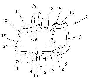
Figure 1 shows a specific embodiment of a bottle-like container 1 of the
invention. Two chambers 2, 3 are arranged side by side, each of which has a
base part 4, 5,
which results in a large, stable support surface for the container 1. A third
chamber 6, which also
has a base part 7, separates the chambers with breakable seams 9, 10. If the
seams 9, 10 break,
for example, by squeezing or pressing the container l, the contents of the
three chambers 2, 3, 6
mix, and the mixed contents can be removed from the container 1 by a, for
example, reclosable
spout 8 in the third chamber 6, which separates the two chambers 2, 3 that are
arranged side by
side.
The three chambers 2, 3, 6, which are arranged side by side here, are each
closed
at the top by a boat-shaped section 9-11 of a molded plastic part. The
reclosable spout 8 can then
also be formed together with them in a simple way. Moreover, the boat-shaped
sections 9-11 can
be provided with openings for filling the three chambers 2, 3, 6. After the
chambers have been
filled -- up to the spout -- the openings are sealed.
The base parts 4, 5, 7 have a pointed-oval shape comparable to the boat-shaped
sections 9-11, and the points of the base parts face each other and are
arranged to make contact
with each other in nodes 16, 17.
The base parts 4, 5, 7 are formed by a single-piece base. Due to the measures
explained above, the unbreakable seam 14 between a film-like front part 15 and
the base parts 4,
5, 7 then also meets the breakable seams 9, 10 at one of the nodes 16, 17. A
similar situation
7
CA 02540642 2006-03-29
exists at the top of the container l, where an unbreakable seam 18 between the
front part 15 and
the boat-shaped sections 11-13 meets the breakable seams 9, 10 in nodes 19,
20.
The same applies to the rear side of the container of the invention.
In the embodiment of a container 24 illustrated in Figure 2, the adjacent
chambers
25, 26 are separated by the breakable seams 27, 28 of a wedge-shaped third
chamber 29. The top
of the chamber 29 has a boat-shaped molded part 30 with a spout 31 that can be
closed by a cap.
The base parts 32, 33 of the chambers 25, 26 are again provided with a pointed-
oval shape and are arranged with the points 34, 35 facing each other. The
seams 27, 28 of the
chamber 29 also form a point 36 that is directed towards these two points 34,
35, so that the
unbreakable seam 38 between a front part 39 and the base parts 32, 33 and the
seams 28, 29 meet
at a node 37.
In the embodiment illustrated in Figure 3, a third chamber 42 arranged between
two adjacent chambers 40, 41 also has a point 43 that is directed towards the
facing points 44, 45
of the pointed-oval base parts 46, 47 of the chambers 40, 41. However, in the
embodiment in
Figure 3, the point 43 continues in another breakable seam 48, which extends
to the points 44, 45
and breakably separates the chambers 40, 41.
The chamber 42 does not have a boat-shaped molded part with a spout, but
rather
a continuous unbreakable seam 49 is provided, which closes the tops of the
chambers 40, 41, 42.
Above the chamber 42, it is formed as a tab SO for an opening. This tab 50 can
be broken open
or broken off, as indicated by the break line 51. Naturally, the force
required to break open the
tab 50 along the break line 51 is greater than the force required to break
open the seams 48, 52,
53 that separate the chambers 40-42.
In the embodiment of the container 60 illustrated in Figure 4, the chamber 61
8
CA 02540642 2006-03-29
again tapers to a point 68 and has breakable seams 62, 63 that separate the
chambers 64, 65,
which are provided with base parts 66, 67.
A fourth chamber 69 with a base part 70 is arranged opposite the chamber 61.
The point 68 of the fourth chamber 69 coincides with the point 68 of the third
chamber 61, so
S that together with the boat-shaped molded part 71, which closes the chamber
61 at the top, the
two chambers 61, 69 with the breakable seams 62, 63 and 72, 73 form a
structure with the shape
of an hourglass. In this container 60 as well, the base parts 66, 67, 70 can
be formed by a
common, single-piece base.
The embodiments of containers illustrated in Figures 1-4 are formed
symmetrically with respect to a center plane. The embodiment of the container
80 illustrated in
Figure 5 does not have symmetry properties of this type.
In the container 80, two adjacent chambers 81, 82 are separated by the seams
85,
86 of a third chamber 83. The seams 85, 86 taper to a point 84, which
continues in another seam
87, which forms a node with the facing points of the two base parts 88, 89 of
the chambers 81,
82.
The chamber 81 is separated from another chamber 90 by a breakable seam 92.
The chamber 90 also has a base part 91, which is formed by a single-piece base
with the other
base parts 88, 89.
A chamber 94, which is separated from chamber 82 by another breakable seam
93, is formed without a base part. The chamber 94 and the chambers 81, 82, 83
are closed at the
top by boat-shaped sections 95-97, and the middle section 96, which closes the
chamber 83, is
provided with a reclosable spout 98.
The container 101 illustrated in Figures 6 and 7 has three adjacent chambers
102,
9
CA 02540642 2006-03-29
103, 104, which are separated from one another by breakable seams 105, 106.
If the container 101 is subjected to a load, e.g., by pressing or squeezing,
the
seams 105, 106 break open, and the contents of the chambers 102, 103, 104 can
be mixed. The
chambers 102, 103, 104 are bounded by a front and a rear plastic film, which
are joined along
their edges by an essentially peripheral seam 107, whose tear strength is
significantly greater
than that of the breakable seams 105, 106, so that there is no danger that
this seam 107 will break
open when a load is applied to the container 101.
Each of the three chambers 102-104 is closed at the bottom by a base part I08-
110. Each base part 108-110 has a filling hole 111-113 for filling the
corresponding chamber
102-104.
The base parts 108-110, which, as an example, are shown here separated from
each other with respect to their peripheral edges, are arranged in a row
supported on a common
stand 114, which is formed here as a base plate 121 with an elongated oval
shape and a suitable
size and thus lends the container 101 a high degree of stability.
Since the base parts 108-110 and the stand 114 are formed as a single piece in
this
embodiment, the filling holes 111-113 also pass through the base plate 121 and
can be sealed by
vibration after the chambers 102-104 have been filled.
Alternatively, if the base parts and stand are formed separately, the filling
holes of
the base parts can also be closed by a continuous base plate 121 after the
chambers 102-104 have
been filled.
A stem 115-117 is additionally arranged between the stand 114 and the base
parts
108-110. The stem 115-117 has a cylindrical cross section, which is recessed
relative to the
corresponding base part 108-110. These stems 115-117 provide a place for fork-
like or tong-like
CA 02540642 2006-03-29
gripping devices to grip and hold the container 101 during a filling
operation. For this reason, it
is advantageous for each stem 115-117 to be free of a film that bounds the
chambers 102-104.
As viewed from above, the base parts 108-110 have a boat-like or wedge-like
shape and thus taper into two opposite points. The points of two adjacent base
parts can be
connected with each other or, as shown in the illustrated embodiment, they can
be separated
from each other. As a consequence, the films that bound the chambers 102-104
can be directly
welded together here over the free space between two adjacent points.
In a side view, as shown, say, in Figure 7, it is apparent that in this
embodiment,
the three chambers 102-104 have an essentially triangular shape. The middle
chamber 103 has a
vertex that points in the direction of the stand 114 and is closed by the base
part 109. The two
outer chambers 102, 104 adjacent to the middle chamber 103 also have an
approximately
triangular shape with their vertices formed above the stand 114 but resting
against the middle
chamber 103 by the seams 105, 106 and the seam 107.
At the top, the triangularly shaped middle chamber 103 has a relatively long
side.
The opposite seams 107 of the front and rear films that form the chamber 103
enclose an insert
118 there, which in a top view is again wedge-shaped or boat-shaped, tapers
into two opposite
points, and is formed as a spout 119 with, for example, a tip 120 that can be
cut off.
Another embodiment of a container 122 is explained in detail with reference to
Figures 8-13
The container 122 is illustrated here, as an example, with two chambers 124,
125
that are separated by a breakable seam 123. Two base parts 126, 127 (cf. also
Figure 4) with
filling holes 128, 129 close the chambers 124, 125 at the bottom.
The base parts 126, 127, which again have a wedge-like shape, are joined by a
11
CA 02540642 2006-03-29
web 130, which is joined to circular stems 131, 132 with recessed cross
sections.
The web 130 is located below a film 133, which bounds the chambers 124, 125
and is joined with the base parts 126, 126 by a seam 134 that cannot be torn
open. The web 130
is thus freely accessible. Consequently, adapters 135, shown here in the form
of recesses with
square cross sections, can be provided on the web 130 for a gripping device,
which grips the
adapters 135 of the web 130 for filling the chambers 124 and 125, holds the
container 122, and
thus allows machine filling through the fillings holes 128 and 129.
The two chambers 124, 125 with the base parts 126, 127, which are formed
separately from each other and are joined by the web 130, are held by a stand
136. The stand
136 has a two-part design with a base plate 137 and a connecting piece 138.
The connecting
piece 138 has two receiving holes 139, 140 for holding the stems 131, 132 of
the base parts 126,
127 fluid-tight. The hole 139 is formed as a blind hole, so that the filling
hole 128 can be closed.
On the other hand, the receiving hole 140 connects the filling hole 129 of the
base
part 127 with a spout 141, cf. Figure 12, so that, for example, liquids mixed
in the chambers 124,
125 can be removed as a mixture from the chambers 124, 125.
The base plate 137 serves as a closure for the spout 141. For this purpose,
the
base plate 137 has a centrally arranged sealing mount or a stopper 142 for the
spout 141.
12