Language selection

Search

Patent 2540717 Summary

Third-party information liability

Some of the information on this Web page has been provided by external sources. The Government of Canada is not responsible for the accuracy, reliability or currency of the information supplied by external sources. Users wishing to rely upon this information should consult directly with the source of the information. Content provided by external sources is not subject to official languages, privacy and accessibility requirements.

Claims and Abstract availability

Any discrepancies in the text and image of the Claims and Abstract are due to differing posting times. Text of the Claims and Abstract are posted:

  • At the time the application is open to public inspection;
  • At the time of issue of the patent (grant).
(12) Patent Application: (11) CA 2540717
(54) English Title: PORTABLE DRILL PRESS
(54) French Title: PERCEUSE A COLONNE PORTATIVE
Status: Deemed Abandoned and Beyond the Period of Reinstatement - Pending Response to Notice of Disregarded Communication
Bibliographic Data
Abstracts

English Abstract


A base which is easily clamped or bolted to work being drilled, attached to
the base a
support column with its longitudinal axis perpendicular the work surface, a
body that can
be adjusted and fixed anywhere along the support column, and a thrust bearing
spindle
assembly offset and parallel to support column that is threadedy engaged with
body. The
thrust bearing is rotated by hand thereby providing a force urging the spindle
towards the
work, the spindle that turns independently of thrust bearing, is easily
engaged by variety
of hand and power tools on one end and has a drill chuck on the opposite end.


Claims

Note: Claims are shown in the official language in which they were submitted.

THE EMBODIMENTS OF THE INVENTION IN WHICH EXCLUSIVE
PROPERTY OR PRIVILEGE IS CLAIMED, ARE DEFINED AS FOLLOWS:
1. Portable drill press apparatus for use with simple hand wrenches and the
like
comprising:
(a) A base that is easily clamped or bolted to the work surface having a
generally flat contacting surface; and
(b) that has a sleeve means slidably engaged on a support column that
extends perpendicular from base, for relative longitudinal and rotative
movements there between; and
(c) having a set screw to secure base to any desired position on support
column.
(d) A cylindrical support column
(e) A Body that has a sleeve means slidably engaged on the support
column for relative longitudinal and rotative movements there between;
and
(f) has a set screw to secure body to any desired position on the support
column; and
(g) has a cylindrical section offset and parallel to support column that is
bored and internally threaded for a portion of it length.
(h) A thrust bearing assembly that is comprised of;
A pressure screw that is generally cylindrical in shape and is externally
threaded for a portion of its length and that threadedly engages with body
(g); and

(i) that has an enlarged flange like portion, to facilitate the rotation of
the
pressure screw-by hand providing a force urging assembly towards the
work; and
(j) is fitted with axial and thrust bearings; and
(k) a spindle which is free spinning within above bearings (i); and
(l) the spindle has hexagonal shape on one end that serves as an interface
for use with simple hand tools (ratchets and sockets, wrenches and the
like), a drill chuck or like means on the other end to engage drill bits; and
(m) has a flange for the engagement of a thrust bearing; and
(n) has a external snap ring to maintain the pressure screw in the correct
longitudinal position on the spindle.
2. Portable drill press apparatus for use with a variety of powered hand tools
(electric and pneumatic drill, ratchets) and the like comprising:
(b) A base that is easily clamped or bolted to the work surface having a
generally flat contacting surface; and
(b) has a sleeve means slidably engaged on a support column that extends
perpendicular from base, for relative longitudinal and rotative movements
there between; and
(c) having a means to secure the base to any desired position on support
column.

(d) A cylindrical support column.
(e) A Body that has a sleeve means slidably engaged on the support
column for relative longitudinal and rotative movements there between;
and
(f) has a means to secure body to any desired position on the support
column; and
(g) has a cylindrical section bored parallel and offset in relation to the
support column, and that is internally threaded for a portion of its length..
(h) A thrust bearing spindle assembly that is comprised of;
A pressure screw that is cylindrical in shape and is externally threaded for
a portion of its length and that it threadedly engages with body (g); and
(i) has an enlarged flange like portion, to facilitate the rotation of the
pressure screw by hand providing a force urging assembly towards the
work; and
(j) is fitted with axial and thrust bearings; and
(k) a spindle which is free spinning within above bearings (i); and
(l) the spindle has means on one end that engages with a variety of power
tools (electric and pneumatic drills, ratchets, and the like), a drill chuck
or
like means on the other end to engage drill bits; and
(m) has a means for the engagement of a thrust bearing; and

(n) a means to maintain the pressure screw in the correct longitudinal
position on the spindle.
3. Portable drill press apparatus for use with a variety of hand and power
tools
comprising:
(a) A base that is easily clamped or bolted to the surface being drilled; and
(b) has a means of mounting a support column perpendicular to the surface
being drilled.
(c) A support column.
(d) A body that has a means of engaging the support column at any desired
position on support column; and
(e) that has section parallel and offset from the support column that is
threadedly engaged with;
(f) a spindle thrust bearing assembly that when rotated by hand has a
means of urging an independently rotating spindle towards work being
drilled.
(g) The spindle with a means of engaging hand tools and a variety of
power tools on one end, a means of retaining a drill bit attached to the
opposite end.

Description

Note: Descriptions are shown in the official language in which they were submitted.


CA 02540717 2006-03-23
Portable Drill Press
In order to be practical, it is necessary that a drill press be quickly and
easily mounted on substantially any surface. In prior art, a large electro-
magnet(s) forms the base of a drill press. Magnetic base drill presses, being
expensive and complex, prove inadequate when the drilling is done on non
ferrous metals. Being large and heavy, accurate placement may prove difficult.
The present invention pertains to a portable drill press apparatus that
includes: a base that is easily clamped or bolted to the surface being drilled
and
a perpendicular column that extends from the base. Said apparatus has a sleeve
means of adjusting and securing the apparatus in relation to material being
drilled. The apparatus has a spindle with a hexagonal shape on one end and a
drill chuck at the other, and further this apparatus has a pressure means
threadedly engaged to force the spindle assembly into the surface being
drilled.
It is the object of the present invention to provide a powerful portable drill
press apparatus that can be clamped or bolted to the work and a hole drilled
manually (utilizing a hand ratchet and socket, or wrench).
It is a further object of this invention to provide a portable drill press
that
can utilize the power of a variety of electric or pneumatic tools (drills, air
ratchets and the like) to assist in the drilling of holes.
It is a further object of this invention to provide a portable drill press
that
can be configured in a variety of ways, so that holes can be drilled in
otherwise
inaccessible positions and locations.
These and other objects of this invention will become apparent to those
skilled in the art upon the consideration of the accompanying specifications,
claims and drawings.
1
~ ~I

CA 02540717 2006-03-23
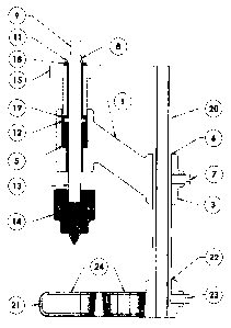
This invention is generally comprised of: (1) Body assembly, (that
includes a (8) Spindle and a (15) Pressure Screw assembly), (20) a Support
Column, (21) Base and (14) Drill Chuck.
Referring to the drawings, wherein like characters indicate like parts
throughout the figures:
Figure 1 is an exploded isometric view;
Figure 2 is an isometric assembly view;
Figure 3 is; an elevation sectional view;
Referring to the figures the numeral (1) generally designates a
parallelogram shaped body with cylindrical sections (2) and (3) on two
opposing sides. Cylinders (2) and (3) have parallel holes bored through their
long axis. Cylinder (2) is bored internally through and threaded for a portion
of
its length (4); the remaining portion is fitted with a bearing (5). Cylinder
(3) is
bored internally (6) and sized to slip fit on support colunm (20) that allows
movement anywhere along column's length, as well as rotating 360 degrees
perpendicular to the support column. Cylinder (3) is bored and fitted with a
set
screw (7) to secure it to support column. It should be understood that the
present
embodiment of this part (1) is simply for illustrative purposes and a variety
of
configurations might be designed by those skilled in the art, all of which
come
within the scope of this invention.
The spindle (8) has a hexagonal section at one end (9), and a groove next
to this section (10) that allows for the placement of an external snap ring
(11).
At the mid-point, the spindle has a circular flange (12). The spindle's other
end
is machined (13) to receive an adjustable drill chuck that holds drill bits
(14).
The hexagonal section (9) provides a means of interface between the spindle
2

CA 02540717 2006-03-23
and a rotational power source (e.g. wrench, socket and (air) ratchet, electric
or
pneumatic drill or other like means) It should be understood that the present
embodiment of spindle (8) is for illustrative purposes and a variety of
configurations might be designed by those skilled in the art, all of which
would
come within the scope of this invention.
The pressure screw (15) is a flanged cylinder that is externally threaded
(16) to mate with (4), and is bored longitudinally (17), and fitted with
internal
axial and thrust bearings at each end (18) and (19) to receive spindle (8) and
allow for free rotation of the spindle. The pressure screw is captured between
(11) and (12) and this thrust bearing assembly is then threadedly engaged with
(4).The flange portion of (15) is knurled to aid with finger grip. When this
thrust
bearing assembly, see figure 2, is threadedly engaged with (4) turning the
flange
clockwise moves this assembly into the work being drilled, when the hole has
been drilled, turning the flange counter clockwise moves this assembly in the
opposite direction and retracts the drill bit from the work.
The support column (20) is a cylindrical shaft.
The base (21) is generally a rectilinear shape with a cylindrical section at
one end bored perpendicular (22) to its top and bottom and sized to slip fit
on
the support column, that allows movement anywhere along the column's length
and allows it to be rotated 360 degrees perpendicular to the support column.
The
base is bored and fitted with a set screw (23) to secure it to the support
column.
Base assembly has slots and holes made perpendicular to its base to allow
bolting to the work being drilled (24). It should be understood that the
present
embodiment of the base (21) is for illustrative purposes and a variety
configurations might be designed by those skilled in the art, all of which
would
come within the scope of this invention.
3
I i .

CA 02540717 2006-03-23
Thus, a new and improved portable drill press apparatus is disclosed
which is convenient to operate and inexpensive to manufacture, further the
drill
press apparatus is constructed so that it can be mounted quickly by means of a
variety of currently available clamping methods, as well as bolted to the work
using existing holes in the material needed to be drilled. Further this drill
press
apparatus can be used with a hand ratchet and socket or a simple hand wrench.
Further this drill press apparatus can utilize a variety of power tools
(electric
hand drills, pneumatic drills and ratchets and the like).
While herein is described a specific embodiment of this invention, further
modifications and improvements may occur to those skilled in the art. It is
desired it to be understood, therefore, that this invention is not limited to
the
particular form shown, and it is intended in the appended claims to cover all
modifications which do not depart from the spirit and scope of this invention.
4
I i

Representative Drawing
A single figure which represents the drawing illustrating the invention.
Administrative Status

2024-08-01:As part of the Next Generation Patents (NGP) transition, the Canadian Patents Database (CPD) now contains a more detailed Event History, which replicates the Event Log of our new back-office solution.

Please note that "Inactive:" events refers to events no longer in use in our new back-office solution.

For a clearer understanding of the status of the application/patent presented on this page, the site Disclaimer , as well as the definitions for Patent , Event History , Maintenance Fee  and Payment History  should be consulted.

Event History

Description Date
Application Not Reinstated by Deadline 2009-03-23
Time Limit for Reversal Expired 2009-03-23
Inactive: Adhoc Request Documented 2008-12-30
Deemed Abandoned - Failure to Respond to Maintenance Fee Notice 2008-03-25
Inactive: Cover page published 2007-09-28
Inactive: IPC assigned 2007-09-27
Inactive: First IPC assigned 2007-09-27
Application Published (Open to Public Inspection) 2007-09-23
Inactive: IPC assigned 2006-07-14
Inactive: Filing certificate - No RFE (English) 2006-04-25
Filing Requirements Determined Compliant 2006-04-25
Inactive: Office letter 2006-04-25
Application Received - Regular National 2006-04-25

Abandonment History

Abandonment Date Reason Reinstatement Date
2008-03-25

Fee History

Fee Type Anniversary Year Due Date Paid Date
Application fee - small 2006-03-23
Owners on Record

Note: Records showing the ownership history in alphabetical order.

Current Owners on Record
ROBERT WILLIAM BUXTON
Past Owners on Record
None
Past Owners that do not appear in the "Owners on Record" listing will appear in other documentation within the application.
Documents

To view selected files, please enter reCAPTCHA code :


To view images, click a link in the Document Description column. To download the documents, select one or more checkboxes in the first column and then click the "Download Selected in PDF format (Zip Archive)" or the "Download Selected as Single PDF" button.

List of published and non-published patent-specific documents on the CPD .

If you have any difficulty accessing content, you can call the Client Service Centre at 1-866-997-1936 or send them an e-mail at CIPO Client Service Centre.


Document
Description 
Date
(yyyy-mm-dd) 
Number of pages   Size of Image (KB) 
Abstract 2006-03-23 1 16
Description 2006-03-23 4 148
Claims 2006-03-23 4 107
Drawings 2006-03-23 1 92
Representative drawing 2007-08-29 1 28
Cover Page 2007-09-28 1 54
Filing Certificate (English) 2006-04-25 1 168
Notice: Maintenance Fee Reminder 2007-12-27 1 121
Courtesy - Abandonment Letter (Maintenance Fee) 2008-05-20 1 178
Second Notice: Maintenance Fee Reminder 2008-09-24 1 118
Notice: Maintenance Fee Reminder 2008-12-24 1 121
Correspondence 2006-04-25 1 14