Note: Descriptions are shown in the official language in which they were submitted.
CA 02541111 2006-03-31
WO 2005/035937 PCT/US2004/031791
MUD FLOW BACK VALVE
FIELD OF THE INVENTION
[0001] The field of the invention is downhole valves and more particularly
valves that can be operated between an open and closed position using the well
fluid
that flows through them.
BACKGROUND OF THE INVENTION
[0002] Downhole valves have been used to provide selective access from
different strata into a well. Typically these valves employ a sliding sleeve
to
selectively align or misalign openings on an inner sliding sleeve mounted
concentrically with a housing. The sliding sleeve can have grooves or recesses
near its
end for engagement by a tool to slide the sleeve in one direction or another.
Typically
the tool to operate the sliding sleeve is delivered on coiled tubing or
wireline,
however, rigid tubing could also be used.
[0003] Many applications in deviated wellbores, particularly those with long
horizontal sections, present unique difficulties to the traditional methods of
operating
sliding sleeve valves with tools delivered on coiled tubing or wireline. Other
applications, such as junctions in multi-lateral systems have such small
inside
diameters so as to malce operation of the sleeve using coiled tubing or
wireline,
virtually impossible.
[0004] One solution to this problem of laclc of access for traditional tools
to
shift the sleeve has been to provide a local source of power, such as a
battery, and use
it to power the sleeve between the open and closed positions. However, there
are still
reliability issues with using battery power and should the valve fail to
close, there is
no backup way to get access to it to get it to close.
[0005] The need to use valves in applications where traditional type of access
is not available, has spurred the need for the present invention. In seeking a
more
reliable way to operate a valve that, in effect, cannot be mechanically
accessed, the
valve of the present invention has been developed. The valve features, in a
preferred
embodiment, an annular passage lined with a material that is sensitive to some
fluids
but not to others. It can remain open until contacted by a fluid that malces
the liner
CA 02541111 2009-06-03
swell. The swelling closes off the flow path through the valve body to allow
subsequent operations to take place. This valve type has particular
application to
screened main bores used in conjunction with open laterals. In such
applications,
high mud flow rates are experienced during completion operations making it
desirable to bypass screens in the main bore completion. However, when
production
of hydrocarbons begins, it is desirable to close the bypass for the screens
and direct
production of hydrocarbons through such screens. The valve of the present
invention
can do this. Exposure to produced hydrocarbons can result in sufficient
swelling to
make the valve close. When this happens, the produced fluid can be directed to
flow
through a screen on the way to the surface. These and other advantages of the
present
invention will become apparent to those skilled in the art from a review of
the
description of the preferred embodiment and the drawings and the claims that
appear
below.
SUMMARY OF THE INVENTION
[0006] A valve for downhole use allows flow of mud or completion
fluids but closes when subjected to produced hydrocarbons. The flow through
the
valve is through an annular passage that features a sleeve preferably made of
rubber.
The passage remains open during completion operations, but when hydrocarbons
are
produced the rubber swells and the passage is closed off. Applications include
completions involving long horizontal runs and small inside diameter laterals
where
access to a sliding sleeve with coiled tubing or a wireline run tool is not
practical.
[0006a] Accordingly, in one aspect of the present invention there is
provided a valve assembly for fluid flow control downhole, comprising:
a valve body having a passage therethrough;
a valve member in said body selectively operable between an
open position and a closed position based on a change in the composition of
the fluid
contacting said valve member; and
a screen having an inner passage and connected to an end
connection such that when said valve member is in said open position, flow in
the
well can pass through said screen inner passage and when said valve member is
in
said closed position, flow in the well must pass through the screen because
said inner
passage is closed off by said valve member.
2
CA 02541111 2009-06-03
[0006b] According to another aspect of the present invention there is
provided a method of well completion and production, comprising:
flowing fluid in a wellbore;
taking flow to the surface through a passage in the interior of a
valve assembly;
closing off said passage in said valve assembly by virtue of a
change in the composition of said fluid;
redirecting said fluid flow due to said closing off;
connecting a screen to said valve assembly;
allowing fluid flow that passes through said valve assembly to
flow through an interior passage in said screen; and
redirecting said fluid flow to go through said screen as a result of
closure of access to said interior passage of said screen by virtue of said
closing of
said passage in said valve assembly.
BRIEF DESCRIPTION OF THE DRAWINGS
[0007] Figure 1 is a section view of a wellbore showing the main bores
completed with screens and the valve of the present invention positioned in
the screen
assemblies adjacent laterals with no production pipe;
[0008] Figure 2 is a detailed view from Figure 1, showing the valve of
the present invention in the open position;
[0009] Figure 3 is the view of Figure 2 with the valve in the closed
position;
2a
CA 02541111 2006-03-31
WO 2005/035937 PCT/US2004/031791
[0010] Figure 4 is a section view through the valve, shown in the open
position;
[0011] Figure 5 is a section through line 5-5 of Figure 4; and
[0012] Figure 6 is a section view through line 6-6 of Figure 4 with the valve
in
the closed position.
DETAILED DESCRIPTION OF THE PREFERRED EMBODIMENT
[0013] Figure 1 illustrates an application of the present invention. Well 10
has
production tubing 12 going to a lateral 14. At lateral 14 the well 10 splits
into
branches 16 and 18, which are respectively cased with casing 20 and 22. The
production tubing 24 and 26 extends respectively through casing 20 and 22 to
respectively terminate in screen assemblies 28 and 30. Branch 16 has several
branches
32 and 34 which are left "barefoot", that is to say there is no production
tubing in
them and this is their condition during completion and in subsequent
production.
Similarly branch 18 has several branches such as 36 and 38 that are likewise
barefoot.
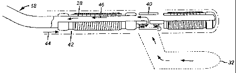
Screen assembly 28 has a valve 40 that allows high flow rates down annulus 42,
represented by arrow 44 shown in Figure 2. These high flow rates of drilling
mud or
other coinpletion fluids can bypass screen assembly 28 from branch 32 by
flowing
through screen assembly 28 after passing through open valve 40. This return
flow is
represented by arrow 46. The same flow pattern exists from branches 36 and 38
into
branch 18 and branch 32 into branch 16. The may be an offset between the start
of a
branch and the valve through which completion fluids or mud will flow. If that
is the
case the flow will go through the annular space around the screen assembly,
such as
28 or 30 until reaching a valve such as 40 or 48.
[0014] As shown in Figure 3, when the valve 40 moves to a closed position
because branch 32 is in production, the flow uphole 50 goes into annulus 42
and
through the screen assembly 28. Essentially the production flow is forced
through the
screen assemblies 28and 30 with the valves 40 and 48 closed due to production
from
the branches below them. This is to be contrasted with the flow pattern
bypassing the
screen assemblies 28 and 30 when valves 40and 48 are open during completion
with
mud or other fluids.
3
CA 02541111 2006-03-31
WO 2005/035937 PCT/US2004/031791
[0015] Figures 4-6 show the operation of one embodiment of the valve 40 or
48. The valve such as 40 has a circular inlet 52 made of a plurality of
smaller
openings 54. Valve 40 has a mandrel 56 with a central passage 58. An annular
path 60
begins near openings 54 and terminates at end wall 62. A series of openings 64
allow
access from annular path 60 into central passage 58. Connection 66 is secured
to the
screen assembly 28 to allow returning mud or other completion fluid to pass
through
the interior of the screen assembly, such as 28. A sleeve 68 is disposed in
annular
passage 60 and when drilling mud or completion fluids are flowing has a small
enough thiclcness to allow high flow rates through annular passage 60 and up
through
the screen assembly 28 to the surface. However, if a branch feeding flow to
valve 40
is allowed to come in and produce hydrocarbons, the sleeve 68 comes in contact
with
the hydrocarbons and proceeds to swell to such an extent so as to bloclc
annular
passage 60 against further flow. The produced stream can no longer short
circuit the
screen assembly 28 by flowing through passage 58. Rather, the produced flow
proceeds outside of coupling 66 until it comes upon a screen section from
screen
assembly 28. At that time, as desired, the produced fluids are forced through
a screen
to limit production of sand or other impurities. Figure 5 shows sleeve 68
before
swelling and Figure 6 shows sleeve 68 after swelling toward the closed
position.
[0016] While the preferred material for sleeve 68 is an elastomer, rubber,
EPDM or Halobutyl which swells dramatically when exposed to hydrocarbons, the
valve of the present invention encompasses other designs that will pass mud
and
completion fluids and can be triggered to close upon commencement of
production
flow. Thus the sleeve 68 can be made of other materials than rubber, such as
elastomers, and does not need to be uniform along its length. It can comprise
of
combinations of materials that exhibit swelling or expand to close a flow path
when
exposed to hydrocarbons. Alternatively, the sleeve material can be sensitive
to
produced or injected water, such as a clay like bentonite. Alternatively, the
material
that will close the valve 40 can be sensitive to any downhole fluid but
isolated from it
during the completion process. Later, when it is desired to put the branches
below
valve 40 into production such that production from those branches will flow
through
the screen the layer 70 that is placed over the sleeve can be defeated, in a
variety of
ways to expose the produced fluids to the sleeve 68 so that it can swell and
close the
annular passage 60. For example the sleeve 68 can be made from clays that
expand
4
CA 02541111 2006-03-31
WO 2005/035937 PCT/US2004/031791
with water such as bentonite or cements or fly ash or other materials that
will swell
and stay rigid enough to redirect flow. The protective cover 70 can be removed
by
being dissolved such as by chemical reaction or other form of attack.
Alternatively,
high flow rates or applied pressure differentials can erode or physically
displace the
protective covering 70. Water can be from produced fluids or deliberately
introduced
from the surface.
[0017] Those skilled in the art can readily see that the various designs
described above allow for a valve to operate reliably in situations where
using coiled
tubing or wireline is not practical. The design removes the uncertainties of
relying on
a downhole battery as the power source to operate the valve. Because of its
simplicity
and reliability of operation, it provides a useful tool when trying to bring
in barefoot
branches that require high flow rates for completion making it imperative to
bypass a
screen assembly while still having the flexibility to later direct produced
flow from
the barefoot branches through a screen assembly, due to the closure of such a
valve.
Other, more common applications of sliding sleeve valves downhole can also
benefit
from the valve of the present invention.
[001$] The foregoing disclosure and description of the invention are
illustrative and explanatory thereof, and various changes in the size, shape
and
materials, as well as in the details of the illustrated construction, may be
made without
departing from the invention.