Note: Descriptions are shown in the official language in which they were submitted.
CA 02541333 2006-04-03
WO 2005/105188 PCT/US2005/013215
BODY PULSATING METHOD AND APPARATUS
FIELD OF THE INVENTION
The invention is directed to a medical device and method to apply repetitive
compression forces to the body of a person to aid blood circulation, loosening
and
elimination of mucus from the lungs of a person and relieve muscular and nerve
tensions.
BACKGROUND OF THE INVENTION
Clearance of mucus from the respiratory tract in healthy individuals is
accomplished
primarily by the body's normal mucociliary action and cough. Under normal
conditions
these mechanisms are very efficient. Impairment of the normal mucociliary
transport
system or hypersecretion of respiratory mucus results in an accumulation of
mucus and
debris in the lungs and can cause severe medical complications such as
hypoxemia,
hypercapnia, chronic bronchitis and pneumonia. These complications can result
in a
diminished quality of life or even become a cause of death. Abnormal
respiratory mucus
clearance is a manifestation of many medical conditions such as ~pertussis,
cystic fibrosis,
atelectasis, bronchiectasis, cavitating lung disease, vitamin A deficiency,
chronic
obstructive pulmonary disease, asthma, and immotile cilia syndrome. Exposure
to cigarette
smoke, air pollutants and viral infections also adversely affect mucociliary
function. Post
surgical patients, paralyzed persons, and newborns with respiratory distress
syndrome also
exhibit reduced mucociliary transport.
2o Chest physiotherapy has had a long history of clinical efficacy and is
typically a part
of standard medical regimens to enhance respiratory mucus transport. Chest
physiotherapy
can include mechanical manipulation of the chest, postural drainage with
vibration, directed
cough, active cycle of breathing and autogenic drainage. External manipulation
of the chest
and respiratory behavioral training are accepted practices as defined by the
American
Association for Respiratory Care Guidelines, 1991. The various methods of
chest
CA 02541333 2006-04-03
WO 2005/105188 PCT/US2005/013215
physiotherapy to enhance mucus clearance are frequently combined for optimal
efficacy and
are prescriptively individualized for each patient by the attending physician.
Cystic fibrosis (CF) is the most common inherited life-threatening genetic
disease
among Caucasians. The genetic defect disrupts chloride transfer in and out of
cells, causing
the normal mucus from the exocrine glands to become very thick and sticky,
eventually
blocking ducts of the glands in the pancreas, lungs and liver. Disruption of
the pancreatic
glands prevents secretion of important digestive enzymes and causes intestinal
problems
that can lead to malnutrition. In addition, the thick mucus accumulates in the
lung's
respiratory tracts, causing chronic infections, scarring, and decreased vital
capacity. Normal
coughing is not sufficient to dislodge these mucus deposits. CF usually
appears during the
first 10 years of life, often in infancy. Until recently, children with CF
were not expected to
live into their teens. However, with advances in digestive enzyme
supplementation, anti-
inflammatory therapy, chest physical therapy, and antibiotics, the median life
expectancy
has increased to 30 years with some patients living into their 50's and
beyond. CF is
inherited through a recessive gene, meaning that if both parents carry the
gene, there is a 25
percent chance that an offspring will have the disease, a SO,percent chance
they will be a
carrier and a 25 percent chance they will be genetically unaffected. Some
individuals who
inherit mutated genes from both parents do not develop the disease. The normal
progression of CF includes gastrointestinal problems, failure to thrive,
repeated and multiple
lung infections, and death due to respiratory insufficiency. While some
patients experience
grave gastrointestinal symptoms, the majority of CF patients (90 percent)
ultimately
succumb to respiratory problems.
A demanding daily regimen is required to maintain the CF patient's health,
even
when the patient is not experiencing acute problems. A CF patient's CF daily
treatments
2s may include:
CA 02541333 2006-04-03
WO 2005/105188 PCT/US2005/013215
3
~ Respiratory therapy to loosen and mobilize mucus;
~ Inhalation therapy with anti-inflammatory drugs, bronchodilators and
antibiotics for
infections;
~ Oral and intravenous antibiotics to control infection;
s ~ Doses of Pulmozyme to thin respiratory mucus;
~ 20 to 30 pancreatic enzyme pills taken with every meal to aid digestion;
~ a low-fat, high-protein diet;
~ Vitamins and nutritional supplements; and
~ Exercise.
1o A lung transplant may be the only hope for patients with end stage cystic
fibrosis.
Virtually all patients with CF require respiratory therapy as a daily part of
their care
regimen. The buildup of thick, sticky mucus in the lungs clogs airways and
traps bacteria,
providing an ideal environment for respiratory infections and chronic
inflammation. This
inflammation causes permanent scarring of the lung tissue, reducing the
capacity of the
15 lungs to absorb oxygen and, ultimately, sustain life. Respiratory therapy
must be
performed, even when the patient is feeling well, to prevent infections and
maintain vital
capacity. Traditionally, care providers perform Chest Physical Therapy (CPT)
one to four
times per day. CPT consists of a patient lying in one of twelve positions
while a caregiver
"claps_" or pounds on the chest and back over each lobe of the lung. To treat
all areas of the
20 lung in all twelve positions requires pounding for half to three-quarters
of an hour along
with inhalation therapy. CPT clears the mucus by shaking loose airway
secretions through
chest percussions and draining the loosened mucus toward the mouth. Active
coughing is
required to ultimately remove the loosened mucus. CPT requires the assistance
of a
caregiver, often a family member but a nurse or respiratory therapist if one
is not available.
25 It is a physically exhausting process for both the CF patient and the
caregiver. Patient and
CA 02541333 2006-04-03
WO 2005/105188 PCT/US2005/013215
caregiver non-compliance with prescribed protocols is a well-recognized
problem that
renders this method ineffective. CPT effectiveness is also highly technique
sensitive and
degrades as the giver becomes tired. The requirement that a second person be
available to
perform the therapy severely limits the independence of the CF patient.
Artificial respiration devices for applying and relieving pressure on the
chest of a
person have been used to assist in lung breathing functions, and loosening and
eliminating
mucus from the lungs of CF persons. Subjecting the person's chest and lungs to
pressure
pulses or vibrations decreases the viscosity of lung and air passage mucus,
thereby
enhancing fluid mobility and removal from the lungs. These devices use vests
having air-
1o accommodating bladders that surround the chests of persons. Mechanical
mechanisms,
such as solenoid or motor-operated air valves, bellows and pistons are
disclosed in the prior
art to supply air under pressure to diaphragms and bladders in regular pattern
or pulses.
Manually operated controls are used to adjust the pressure of the air and air
pulse frequency
for each patient treatment and during the treatment. The bladder worn around
the thorax of
~s the CF person repeatedly compresses and releases the thorax at frequencies
as high as 25
cycles per second. Each compression produces a rush of air through the lobes
of the lungs
that shears the secretions from the sides of the airways and propels them
toward the mouth
where they can be removed by normal coughing. External chest manipulation with
high
frequency chest wall oscillation was reported in 1966. Beck GJ. Chronic
Bnorzchial Asthma
2o and Emphysema. Rehabilitation and Use of Thoracic
Tlibrocomp~°ession, Gee°iatrics (1966);
21: 139-158.
G.A. Williarns in U.S. Patent No. 1,898,652 discloses an air pulsator for
stimulating
blood circulation and treatment of tissues and muscles beneath the skin. A
reciprocating
piston is used to generate air pressure pulses which are transferred through a
hose to an
2s applicator having a flexible diaphragm. The pulsating air generated by the
moving piston
CA 02541333 2006-04-03
WO 2005/105188 PCT/US2005/013215
imparts relatively rapid movement to the diaphragm which subjects the person's
body to
pulsing forces.
J.D. Ackerfna~ et al in U.S. Patent No. 2,588,192 disclose an artificial
respiration
apparatus having a chest vest supplied with air under pressure with an air
pump. Solenoid-
s operated valves control the flow of air into and out of the vest in a
controlled manner to
pulsate the vest, thereby subjecting the person's chest to repeated pressure
pulses.
J.H. Enzerso~ in U.S. Patent No. 2,918,917 discloses an apparatus for
exercising and
massaging the airway and associated organs and loosening and removing mucus
therefrom.
A blower driven with a motor creates air pressure for a device that fits over
a person's nose
to and mouth. A diaphragm reciprocated with an electric motor pulses the air
flowing to the
device and the person's airway. The speed of the motor is controlled to
regulate the number
of vibrations per minute.
R.F. Gray in U.S. Patent No. 3,078,842 discloses a bladder for cyclically
applying
an external pressure to the chest of a person. A pressure alternator applies
air pressure to
1s the bladder. A pulse generator applies air pressure to the bladder to apply
pressure pulses to
the chest of the person.
R.S. Dillio~ in U.S. Patent No. 4,590,925 uses an inflatable enclosure to
cover a
portion of a person's extremity, such as an arm or leg. The enclosure is
connected to a fluid
control and pulse monitor operable to selectively apply and remove pressure on
the person's
20 extremity.
W.J. Warwick and L. G. Hanse~ in U.S. Patent Nos. 4,838,263 and 5,056,505
disclose a chest compression apparatus having a chest vest surrounding a
person's chest. A
motor-driven rotary valve allows air to flow into the vest and vent air
therefrom to apply
pressurized pulses to the person's chest. An alternative pulse pumping system
has a pair of
25 bellows connected to a crankshaft with rods operated with a do electric
motor. The speed of
CA 02541333 2006-04-03
WO 2005/105188 PCT/US2005/013215
6
the motor is regulated with a controller to control the frequency of the
pressure pulses
applied to the vest. The patient controls the pressure of the air in the vest
by opening and
closing the end of an air vent tube.
C.N. Ha~sen in U.S. PatentNos. 5,453,081 and 5,569,170 discloses an air
pulsating
apparatus for supplying pulses of air to an enclosed receiver, such as a vest
located around a
person's chest. The apparatus has a casing with an internal chamber containing
a
diaphragm. An electric operated device connected to the diaphragm is operated
with a pulse
generator to vibrate the diaphragm to pulse the air in the chamber. A hose
connects the
chamber with the vest to transfer air and air pulses to the vest which applies
pressure pulses
1o to the person's chest.
N.P. Yah Bunt and D.J. Gaghe in U.S. Patent Nos. 5,769,797 and 6,036,662
disclose an oscillatory chest compression device having a wall with an air
chamber and a
diaphragm mounted on the wall and exposed to the air chamber. A rod pivotally
connected
to the diaphragm and rotatably connected to a crankshaft transmits force to
the diaphragm
during rotation of the crankshaft. An electric motor drives the crankshaft at
selected
controlled speeds to regulate the frequency of the air pulses generated by the
moving
diaphragm. An air flow generator, shown as a blower, delivers air to the air
chamber to
maintain the pressure of the air in the chamber. Controls for the motors that
move the
diaphragm and rotate the blower are responsive to the air pressure pulses and
pressure of the
2o air in the air chamber. These controls have air pulse and air pressure
responsive feedback
systems that regulate the operating speeds of the motors to control the pulse
frequency and
air pressure in the vest.
C.N. Hanseh in U.S. Patent No. 6,488,641 discloses a pulsator operable to
generate
repetitive air pressure pulses used to apply pressure pulses to a human body.
The pulsator
has a scotch yoke motion transmitting mechanism for reciprocating diaphragms
to generate
CA 02541333 2006-04-03
WO 2005/105188 PCT/US2005/013215
repetitive air pressure pulses. A manually adjusted analog control coupled to
a brush
electric motor is used to control the speed of the motor and reciprocating
frequency of the
diaphragms. The control must be manually adjusted for each use and different
users of the
pulsator according to a prescribed or desired treatment. Manual adjustments of
the speed of
the motor to change the frequency of the pressure pulses can be made during
use of the
pulsator.
C.N. Hahsen in U.S. Patent No. 6,547,749 discloses a pulsator having two
diaphragms connected to scotch yokes which transmits rotary motion of a brush
do electric
motor to reciprocating motions of the diaphragm to generate air pressure and
air pulses.
1o The scotch yokes are subject to surface wear due to prolonged strains and
friction resulting
in vibrations and noise. A first manually operated control is used to select
the frequency of
the air pulses by controlling the speed of the motor. A second manually
operated control is
used to adjust the pressure of the air generated by the pulsator. These
controls must be
manually adjusted for each use and during use of the pulsator according to a
prescribed or
described treatment. The controls have manually turned knobs to adjust the
pulse frequency
and air pressure generated by the pulsator. The user must remember the
frequency and
previous air pressure or have written instructions for these settings for
consistent treatment.
SUMMARY OF THE INVENTION
The invention is a medical device used to deliver high-frequency chest wall
oscillations to promote airway clearance and improve bronchial drainage in
humans. The
primary components of the device include an air-pulse generator, an air
inflatable vest, and
a flexible hose coupling the generator to the vest for transmitting air
pressure and pressure
pulses from the generator to the vest. The vest includes an air core or
bladder connected
with the hose to the generator. Air pressure pulses subjected to the air core
create repetitive
2s high frequency pressure pulses that are transmitted to the thorax of a
person wearing the
CA 02541333 2006-04-03
WO 2005/105188 PCT/US2005/013215
vest whereby high frequency chest wall oscillations enhance mucus clearance in
the
person's respiratory system. The air pressure pulses are established with
movable
diaphragms located between air pumping chambers and an air pulsing chamber.
Scotch
yoke motion transmitting mechanisms change rotatory motion from a brushless do
electric
s motor to reciprocating movements of the diaphragms. The reciprocating
diaphragms pump
air to increase air pressure and pulse the air by increasing and decreasing
air pressure in a
chamber in communication with the hose. Each scotch yoke motion transmitting
mechanism includes a yoke secured directly to a diaphragm, a shuttle slidably
mounted on
the yoke and an eccentric on a shaft rotatably mounted in the shuttle. An anti-
lash assembly
1o has a lash plate biased against the shuttle to compensate for manufacturing
tolerances,
thermal growth, and wear of the shuttle and yoke, to reduce stress and impact
forces and
inhibit vibrations and noise. The anti-lash assembly has a lash plate biased
with springs into
continuous engagement with the shuttle. A guide pin mounted on the yoke
maintains the
lash plate aligned with the shuttle. The power supply for the brushless do
motor includes a
15 digital frequency control component that also controls the time or duration
of operation of
the device. The control component has memory microchips that store time and
frequency
data for ease and reliable use. A control panel has a screen having manual
display coupled
to time and frequency keys which are manually operated to change the time and
frequency
programs or change manual time and frequency operation of the device. The air
pressure in
2o the vest is regulated with an adjustable air flow restrictor that limits
the flow of air into an
air pumping chamber thereby controlling the pressure of the air in the air
pumping chamber,
air pulsating chamber and bladder of the vest.
The preferred embodiment of the body pulsating apparatus has a case with walls
surrounding an air pulsing chamber. An elongated hose carries air and air
pulses to an air
25 core in a vest located about the upper body of a person. The case has an
internal wall that
CA 02541333 2006-04-03
WO 2005/105188 PCT/US2005/013215
separates the air pulsing chamber from an air manifold chamber. One or more
one-way
valves mounted on the internal wall allow air to flow from the air manifold
chamber into the
air pulsing chamber and prevent reverse flow of air back from the air pulsing
chamber into
the air manifold chamber. The case has top and bottom openings covered with
diaphragms
attached with flexible peripheral members to the case to enclose the air
pulsing chamber.
Located within the air pulsing chamber is a pair of linear reciprocating
motion transmitting
mechanisms for linearly moving the diaphragms in straight line opposite
directions to pulse
the air in the air pulsing chamber. The motion transmitting mechanisms are
scotch yokes
which provide the diaphragms with straight line harmonic motions. An electric
brushless do
1o motor rotates a common shaft having a pair of eccentrics that laterally
moves shuttles with
respect to the yolces, and reciprocates yokes with respect to the yoke guides.
The yokes are
fixed directly to the diaphragms. Each scotch yoke includes an anti-lash
assembly to
compensate for wear of the shuttle and yoke, allow for thermal growth and
relaxed
manufacturing tolerances, and prevent movement of the shuttle normal to its
lateral
movements relative to the yoke to reduce stress and impact forces on the
shuttle and inhibits
vibrations and noise. The anti-lash assembly has a flat lash plate located in
surface
engagement with the top surface of the shuttle. A pair of compression coil
springs mounted
on the yoke bias the lash plate against the shuttle. A cylindrical guide pin
fixed to the yoke
extends into a hole in the lash plate to maintain the lash plate aligned with
the shuttle and
2o allow the lash plate to compensate for wear of the shuttle, yoke and lash
plate. The
operating speed of the motor is controlled with a motor controller wired to a
screen and time
and frequency adjusting lceys. The controller is programmable to change the
speed of the
motor which is proportional to air pulse frequency in the air pulsing chamber.
Covers
located over the diaphragms attached to the casing have air pumping chambers
in
communication with the manifold chamber. The inward reciprocating movements of
the
CA 02541333 2006-04-03
WO 2005/105188 PCT/US2005/013215
diaphragms draws air through an air flow control into air manifold chamber and
pumping
chambers and the outward reciprocating movement of the diaphragms then
compresses the
air in the air manifold chamber and pumping chambers. The pressure of the air
in the air
manifold chamber is regulated with a manually adjustable air flow control
valve.
5 Restricting the flow of air into the manifold chamber reduces the pressure
of the air in the
air manifold chamber. When the pressure of the air in the air manifold chamber
exceeds the
air pressure in the air pulsing chamber, the one-way valve opens to allow air
to flow into the
air pulsing chamber. The reciprocating movements of the diaphragms pulse the
pressurized
air at a frequency determined by the speed of the electric brushless do motor
that drives the
l0 scotch yokes.
DESCRIPTION OF THE DRAWINGS
Figure 1 is a diagrammatic view of the air pressure and pulse generator of the
invention coupled to an air core located in a vest located around the thorax
of a person;
Figure 2 is a diagrammatic view, partly sectioned, of the air core, vest, and
person of
Figure 1;
Figure 3 is a top plan view of the time and frequency control panel of the air
pressure and pulse generator of Figure l;
Figure 4 is a top plan view of the air pressure manual control of the air
pressure and
pulse generator of Figure 1;
2o Figure 5 is a diagrammatic view of the air pressure and pulsating apparatus
of Figure
1;
Figure 6 is a cross-sectional diagrammatic view of the air pressure and pulse
generator of Figure 1;
Figure 7 is a pressure time graph of the air pressure and pulse generator of
Figure 1;
Figure 8 is an enlarged sectional view taken along line 8-8 of Figure 5;
CA 02541333 2006-04-03
WO 2005/105188 PCT/US2005/013215
11
Figure 9 is a sectional view taken along line 9-9 of Figure 8;
Figure 10 is a sectional view taken along line 10-10 of Figure 9;
Figure 11 is a sectional view taken along line 11-11 of Figure 8;
Figure 12 is a sectional view taken along line 12-12 of Figure 1 l;
Figure 13 is a sectional view taken along line 13-13 of Figure 11;
Figure 14 is a sectional view similar to Figure 8 showing the diaphragm
assemblies
in the air pumping mode;
Figure 15 is a sectional view similar to Figure 8 showing the diaphragm
assemblies
in the air pulsing mode;
1o Figure 16 is an enlarged sectional view of the scotch yoke mechanism taken
along
line 16-16 of Figure 15;
Figure 17 is a sectional view taken along line 17-17 of Figure 16;
Figure 18 is a sectional view taken along line 18-18 of Figure 16;
Figure 19 is a diagram of the manual sequence of the operation of the time and
15 frequency controls of the generator;
Figure 20 is a diagram of the time count down screen during manual operation
of the
generator;
Figure 21 is a diagram of the screen during paused manual operation of the
generator; and
2o Figure 22 is a diagram of the program sequence of the operation of the time
and
frequency controls of the generator.
DESCRIPTION OF PREFERRED EMBODIMENT
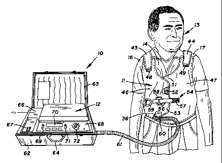
The body pulsating apparatus, indicated generally at 10 in Figure 1, has a
vest 11
and an air pressure and pulse generator 12 operable to apply repetitive
pressure pulses to the
2s vest located about a human body to provide secretion and mucus clearance
therapy.
CA 02541333 2006-04-03
WO 2005/105188 PCT/US2005/013215
12
Respiratory mucus clearance is applicable to many medical conditions, such as
pertussis,
cystic fibrosis, atelectasis, bronchiectasis, cavitating lung disease, vitamin
A deficiency,
chronic obstructive pulmonary disease, asthma, and immobile cilia syndrome.
Post surgical
patients, paralyzed persons, and newborns with respiratory distress syndrome
have reduced
s mucociliary transport. Apparatus 10 provides high frequency chest wall
oscillations or
pulses to enhance mucus and airway clearance in a person 13 with reduced
mucociliary
transport.
Vest 11 located around the person's upper body or thorax 14 is supported on
the
person's shoulders 16 and 17. As shown in Figure 2, vest 11 expanded into
substantial
to surface contact with the exterior of upper body 14 functions to apply
repeated compression
or pressure pulses, shown by arrows 18 to body 14. The reaction of body 14 to
the pressure
pulses causes repetitive expansion of the body when the pressure pulses are in
the low
pressure phase of the pressure cycle. The pressure pulses subjected to lungs
19 and 21 and
trachea 22 provide secretions and mucus clearance therapy. The thoracic cavity
occupies
is only the upper part of the thoracic cage and contains right and left lungs
19 and 21, heart 23,
arteries 24 and 26, and rib cage 27. The repeated pressure pulses applied to
thorax 14
stimulates heart 23 and blood flow in arteries 24 and 26 and veins in the
chest cavity.
Muscular and nerve tensions are also relieved by the repetitive pressure
pulses imparted to
the front, sides, and back portions of thorax 14. The lower part of the
thoracic cage
2o comprises the abdominal cavity 29 which reaches upward as high as the lower
tip of the
sternum so as to afford considerable protection to the large and easily
injured abdominal
organs, such as the liver, spleen, stomach, and kidneys. The two cavities are
separated by a
dome-shaped diaphragm 28. Rib cage 27 has twelve ribs on each side of the
trunk. The
ribs consist of a series of thin, curved, rather elastic bones which
articulate posteriorly with
25 the thoracic vertebrae. The spaces between successive ribs are bridged by
intercostal
CA 02541333 2006-04-03
WO 2005/105188 PCT/US2005/013215
13
muscles. The rib cage 29 aids in the distribution of the pressure pulses to
the lungs 19 and
21 and trachea 22.
Vest 11 has an outside cover 31 comprising a non-elastic material, such as a
nylon
fabric. Other types of materials can be used for cover 31. Cover 31 is secured
to a flexible
inside liner 32 located adjacent and around body 14. Liner 32 is a flexible
fabric, such as a
porous cotton fabric, that allows air to flow through the fabric toward body
14. A closure
device 33, shown as a zipper, secures the bottom of liner 32 to an upwardly
directed end
portion 34 of cover 31. An air core or bladder 36 having internal chamber 37
and a
manifold passage 38 is located between cover 31 and liner 32. A plurality of
air passages
l0 39 between passage 38 and chamber 37 allow air to flow upwardly into
chamber 37. An
elongated coil spring 41 in the lower portion of air core 36 inside manifold
passage 38
maintains the manifold passage 38 open. Other types of structures that
maintain manifold
passage 38 open and allow air to flow through passage 38 can be used in the
lower portion
of air core 36. The end portion 33 of non-elastic cover 31 and coil spring 41
substantially
1s reduces the inward pressure of the vest on the abdominal cavity 29 and
organs therein and
reduces stress on the digestive system. Air core 36 has a plurality of
vertically aligned air
flow control apertures 42 that restrict the flow of air from air core chamber
37 into the space
between cover 31 and liner 32. The air flowing through porous liner 32
ventilates and cools
body 14 surrounded by vest 11.
2o Returning to Figure l, vest 11 has a pair of upright shoulder straps 43 and
44
laterally separated with a concave upper back edge. Upright front chest
portions 46 and 47
are separated from straps 43 and 44 with concave curved upper edges which
allow vest 11
to fit under the person's arms. Releasable fasteners, such as loop pads 48 and
49, secured to
the outer surfaces of chest portions 46 and 47 cooperate with hook pads (not
shown) secured
25 to the insides of shoulder straps 43 and 44 to releasably connect shoulder
straps 43 and 44 to
CA 02541333 2006-04-03
WO 2005/105188 PCT/US2005/013215
14
chest portions 46 and 47. Shoulder straps 43 and 44 extend forwardly over
shoulders 16
and 17 and downwardly over chest portions 46 and 47. The hook and loop pads
are
releasable VELCRO fasteners that connect shoulder straps 43 and 44 to chest
portions 46
and 47 and hold chest portions 46 and 47 adjacent the front of body 14.
Vest 11 has a first lateral end flap 51 extended outwardly at the left side of
the vest.
A rectangular loop pad 52 secured to the outside of the end flap 51 cooperates
with hook
pads on a second lateral end flap 53 on the right side of vest 11 to hold vest
11 around body
14. The hook and loop pads are VELCRO fasteners that allow vest 11 to be
tightly wrapped
around body 14.
1o As shown in Figure 1, a releasable retainer 54 connected to the vest end
flaps hold
the flaps 51 and 53 in over lapped positions and prevents the releasable hook
and loop
fasteners 52 from disengaging during the application of repetitive pulse to
the body 14 on
the person 13. Retainer 54 comprises an elongated strap 56 secured at one end
thereof to
chest portion 53. Opposite ends of strap 56 have hook and loop releasable
fasteners 57 that
is allow strap 56 to be fastened into a D-ring. A pair of D-rings 58 and 59
attached to chest
portion 46 are aligned with strap 56. Strap 56 is looped through D-ring 58 and
connected
with fasteners 57 to hold the vest end flaps 51 and 53 and vest 11 around the
body 14 of the
person. The free end of strap 56 can be quickly pulled to release fasteners 57
and disengage
retainer 54. C.N. Ha~sen and L.J. Helgesore in U.S. Patent No. 6,676,614
disclose a vest
20 operable to subject a person's thorax to pressure pulses.
In use, vest 11 is placed about the person's body 14, as shown in Figure 1,
and held
in place with shoulder straps 43 and 44. Releasable fasteners 48 and 49 secure
straps 43
and 44 to chest portions 46 and 47. The vertical location of vest 11 on body
14 is adjusted
by changing the connection relationship of straps 43 and 44 on releasable
fasteners 48 and
25 49. The circumferential location of vest 11 is maintained in a light fit
around the person's
CA 02541333 2006-04-03
WO 2005/105188 PCT/US2005/013215
body 13 with releasable fasteners 52. Retainer 54 maintains fasteners 52 in
engagement
with each other and prevents disengagement during the pulsating of vest 11.
Strap 56 of
retainer 54 is looped through one of the D-rings 58, 59 and attached together
with hook and
loop fasteners 57. Air pulsator 12 is then connected with hose 61 to tube 62
at and end of to
5 apply repetitive pressure pulses to body 14 of person 13.
Air pressure and pulse generator 12 is mounted in a case 62 having an open top
and
a cover 63 hinged to case 62 operable to close case 62. A handle 64 pivotally
mounted on
case 62 is used as a hand grip to facilitate transport of generator 12. Case
62 and cover 63
have overall dimensions that allow the case to be an aircraft carryon item.
1o Air pressure and pulse generator 12 has a top member 66 mounted on case 62
enclosing the operating elements of the generator. Top member 66 is not
readily removable
from case 62 to prohibit unauthorized adjustments and repairs of the operating
components
of the air pressure and pulse generator 12. Top member 67 supports a main
electric power
switch 67 and a front panel 68 having time control keys 69, an information
display screen
15 70, frequency control keys 71 and an air pressure manual control Irnob 72.
Time control
keys 69 are electronic switches comprising an upper + key and a lower - key to
selectively
program an increase or decrease of a treatment cycle between 0 to 30 minutes.
The selected
time period is registered on screen 70. Screen 70 is an electronic viewing
display device,
such as a liquid crystal display or a light-emitting organic material display.
Frequency
2o control keys 71 are electronic switches comprising an upper + key and a
lower - lcey to
selectively program an increase or decrease of the pulse frequency between 5
and 25 cycles
per second or Hz. As shown in Figure 1, time control key 69, information
display screen
70, frequency control key 71 and air pressure control knob 72 are located on
front panel 68
for user friendly convenience and use. The adjustment of the air pressure in
air core 36 is
controlled by manually turning knob 72. The average air pressure in air core
36 is
CA 02541333 2006-04-03
WO 2005/105188 PCT/US2005/013215
16
controlled between atmosphere pressure and one psi, as shown in Figure 4 by
pressure scale
73 with numbers 10 to 100. The oscillating pressure pulses cycle above and
below the
selected average pressure.
As shown in Figures 5, 6, 7 and 11, air pressure and air pulse generator 12
has a
combined air pulsator and pump unit 78 operable to create air pressure pulses,
shown by
arrows 79, which are transported by hose 61 to air core 36. Unit 78 has a
rectangular case
81 having upright side walls 82 and 83 joined to end walls 84 and 85. An
internal wall 86
extended between and joined to side walls 82 and 83 separates an air pulsing
chamber 87
from a manifold or vestibule chamber 88. Manifold chamber 88 is between end
wall 85 and
1o inside wall 86. The top and bottom of casing 81 is open. A pair of
diaphragms 89 and 91
mounted on casing 81 close the casing openings to enclose the air pulsing
chamber 87
located between diaphragms 89 and 91. A first pan-shaped cover 92 secured to
the top of
case 81 with fasteners 93 is located outwardly of diaphragm 89. The space
between cover
92 and diaphragm 89 is a first pumping chamber 94 in fluid communication with
manifold
chamber 88 to allow air to flow into and out of chamber 94. A second pan-
shaped cover 96
secured to the bottom of case 81 with fasteners 97 is located outwardly from
diaphragm 91.
The space between cover 96 and diaphragm 91 is a second air pumping chamber 98
in fluid
communication with the manifold chamber 88 to allow air to flow between
chambers 88
and 98. Air flows from pumping chambers 94 and 98 into manifold chamber 88 and
from
2o manifold chamber 88 into pulsing chamber 87 through a one-way valve or
check valve 99,
shown by arrow 100 in Figure 14. Valve 99 when closed, as shown in Figure 8,
prevents
the flow of air from pulsing chamber 87 back to manifold chamber 88. Valve 99,
shown in
Figure 8, has a cylindrical housing 101 mounted on wall 86. Housing 101 has a
passage
102 open to chambers 87 and 88 accommodating a valuing member or disk 103
movable
2s between open and closed positions. A transverse pin 104 mounted on housing
101 retains
CA 02541333 2006-04-03
WO 2005/105188 PCT/US2005/013215
17
disk 103 in passage 102 and provides a fulcrum for disk 103 to allow disk 103
to pivot to its
open position. One or more one-way valves mounted on wall 86 can be used to
permit air
to flow from manifold chamber into pulsating chamber 87 and block reverse flow
of air
from pulsating chamber 87 back to manifold chamber 88.
Diaphragm 89 has a rectangular rigid metal plate 106 joined to a peripheral
flexible
flange 107 of rubber or plastic. The inner portion of flange 107 is bifurcated
and bonded to
opposite sides of plate 106. The outer portion of flange 107 is clamped with
fasteners 93
between cover 92 and casing 81. As shown in Figures 8, 9, 14 and 15, flange
107 has an
opening 108 allowing air to flow between first pumping chamber 94 and manifold
chamber
to 88. Flexible flange 107 has a flexible convolution fold section 109
comprising upward and
downward directed ribs that allow linear lateral movement of plate 106 without
stretching
and stressing the flexible material of flange 107. Diaphragm 91 has a rigid
metal plate 11
located on the bottom side of chamber 87 and parallel to plate 106. A flexible
flange 112
joined to plate 106 is clamped with fasteners 97 between casing 81 and cover
96. Flange
15 112 has an opening 113 allowing air to flow between manifold chamber 88 and
second
pumping chamber 98. A middle section of flange 112 around plate 111 has a
flexible
convolution fold section that allows linear lateral movement of plate 111
without stretching
and stressing the flexible material of flange 112.
Diaphragms 89 and 91 are linearly moved in opposite lateral directions with
linear
2o motion transmission assemblies indicated generally at 116 and 117 driven
with a variable
speed brushless do electric motor 118. A belt and pulley power transmission
119 driveably
connects motor 118 to motion transmission assemblies 116 and 117. As shown in
Figures
11 and 13, motion transmission assembly 116 has a cross member 121 secured
with
fasteners 122 and 123 to casing side walls 82 and 83. Member 121 has a pair of
parallel
2s upright guide surfaces 124 and 126. A yolee 127 having opposite sides
located in sliding
CA 02541333 2006-04-03
WO 2005/105188 PCT/US2005/013215
18
engagement with guide surfaces 124 and 126 is secured to plate 106 with a pair
of bolts 128
and 129. Bolts 128 and 129 extended through holes 131 and 132 in plate 107
prevent
relative movement, including pivotal movement, between yoke 127 and plate 106.
Yoke
127 has only linear reciprocating movement which prevents rocking and angular
movement
of diaphragm 89 during reciprocation thereof. As seen in Figure 13, yoke 127
has a lateral
opening or window 133 accommodating a slide bloclc or shuttle 134. Shuttle 134
has a bore
accommodating an eccentric 136 mounted on a shaft 137. Eccentric 136 is
surrounded with
a roller bearing 138 located in the bore of shuttle 134. Yoke 127, shuttle
134, eccentric 136
and shaft 137 are known as a scotch yoke power transmission assembly.
to As shown in Figures 16 to 18, bolts 128 and 129 secure the top of yoke 127
to
diaphragm plate 106. An anti-lash assembly 200 bears against the flat top
surface 209 of
shuttle 134 to maintain the bottom surface 205 of shuttle 134 in sliding
surface contact with
flat surface 210 of yoke 127. Anti-lash assembly 200 compensates for
manufacturing
tolerances, thermal growth, and wear of shuttle surfaces 205 and 209 and
adjacent yoke
surfaces and maintains surfaces 205, 210 and 208, 209 in sliding contact to
reduce stress
and impact forces and inhibits vibrations and noise. A lash plate 201 has flat
surface 208
located in sliding contact with shuttle flat surface 209. Plate 201 is a steel
member having a
central cylindrical hole 202 accommodating a cylindrical guide pin 203. Hole
202 can
extend through plate 201. Pin 203 is press fitted or secured into a
cylindrical bore 204 in
2o the top of yoke 127. The lower end of pin 203 has a slip fit in hole 202 to
allow lash plate
201 to move down to maintain surface engagement with the top surface 209 of
shuttle 134.
Opposite ends 206 and 207 of lash plate 201 are maintained spaced from
adjacent inside
walls of yoke 127 with pin 203. A pair of coil compression springs 211 and 212
bias lash
plate 201 into continuous surface contact with the surface 209 of shuttle 134.
Springs 211
and 212 located in cylindrical bores 213 and 214 in the top of yoke 127 extend
downwardly
CA 02541333 2006-04-03
WO 2005/105188 PCT/US2005/013215
19
into cylindrical recess 216 and 217 in lash plate 201. Other types of biasing
members, such
as elastic rubber or plastic cores, can be used for continuously biasing lash
plate 201 down
against shuttle 134.
A second scotch yoke power transmission assembly operatively connected to
plate
111 of diaphragm 91 comprises a yoke 139 secured with a pair of bolts 140 and
141 to plate
111. Bolts 140 and 141 prevent relative movement, including pivotal movement,
of yoke
139 relative to plate 111 whereby diaphragm 91 has only linear reciprocating
movements.
Yoke 139 has outside upright sides located in sliding engagement with upright
guide
surfaces 142 and 143 of a second cross member 144 which restricts movement of
yoke 139
to to reciprocating linear movement. Returning to Figure 11, fasteners 146 and
147 secure
cross member 144 to casing side walls 82 and 83. Second cross member 144 is
located
adjacent first cross member 121 and rotatably accommodates the outer end of
shaft 137, as
shown in Figures 8, 14 and 15. Yolce 139 has an opening or window 148 slidably
accommodating a slide block or shuttle 149 having a cylindrical bore for a
roller bearing
152 and eccentric 151 secured to shaft 137. Eccentric 151 is located
diametrically opposite
eccentric 136, as shown in Figure 14, so as to provide rotational balance to
the scotch yoke
power transmission assemblies.
An anti-lash assembly 218, shown in Figures 8, 12, 14 and 15, biases a lash
plate
into continuous surface engagement with shuttle 149 of the scotch yoke secured
to
2o diaphragm plate 111 with bolts 140 and 141. Anti-lash assembly 218 has the
same
structures and functions as anti-lash assembly shown in Figures 16 to 18.
Returning to Figure 11, belt and pulley power transmission 119 has a small
drive
pulley 153 connected to drive shaft 154 of motor 118. A first endless belt 156
located about
pulley 153 and a large pulley 157 secured to a jack shaft 158 transmits power
to shaft 137
with a small pulley 162 on jack shaft 158 and an endless belt 163 coupling
pulley 162 to a
CA 02541333 2006-04-03
WO 2005/105188 PCT/US2005/013215
large pulley 164 secured to shaft 137. The small and large pulleys 153, 157
and 162, 164
provide power transmission 119 with speed reduction operation of shaft 137. As
shown in
Figures 6, 8 and 11, motion transmission assemblies 116 and 117, and belt and
pulley power
transmission 119 are located in pulsing chamber 87 and are surrounded by
casing 81 and
5 diaphragms 89 and 91. The isolation of the motion transmission assemblies
116 and 117 in
chamber 87 reduces noise and protects these assemblies and belt and pulley
power
transmission 119 from external environmental contaminates.
As shown in Figure 5, a brushless electric do motor 118 mounted on a side of
air
pulsator and pump unit 78 is wired to a programmable power supply 165 for
controlling the
1o time of operation of the unit and the frequency of the generated air
pulses. Power supply
166 is adapted to be connected to either 110 volt 60 cycle or 220 volt 50
cycle power
sources. A manually operated switch 67 connects the power source to a circuit
board 166
operable to supply do power to a digital controller 170 wired to motor 118 and
control panel
keys 69, 71, 74, 75 and 76 and screen 70. Controller 170 has programmable
electronics
15 including dynamic random access memory micro chips for controlling the
operating time
and speed of motor 118. Plus and minus time keys 69 are used to set the
operation time of
pulsator 12 between 0 and 30 minutes in 30 second intervals. Plus and minus
frequency
keys 71 are used to set the frequency of the air pulses by regulating the
operating speed of
motor 118 to adjust the pulse frequency between 5 and 25 pulses per second or
Hz intervals.
2o Manual and programmable data is displayed on screen 70 as hereinafter
described.
The pressure of the air in manifold chamber 88 is controlled with a variable
orifice
proportional free-flow valve 167 operable to restrict or choke the flow of air
into and out of
manifold chamber 88. Valve 167 has a body 168 having a passage 169. An air
flow
restrictor 171, shown as a threaded member, mounted on body 168 and extended
into
passage 169 regulates the flow of air through passage 169 into a tube 172.
Other types of
CA 02541333 2006-04-03
WO 2005/105188 PCT/US2005/013215
21
air flow restrictors, such as a rotatable grooved ball or a movable disk, can
be used to
regulate air flow through valve 167. The remote end of tube 172 is connected
to an elbow
173 mounted on casing wall 85. Elbow 173 has a passage 174 open to manifold
chamber
88 to allow air to flow into manifold chamber 88. A passage 175 in body 168
allows a
limited amount of air to flow into passage 174 into manifold 88. Passage 175
is a fixed air
flow passage in body 168 that allows air to by-pass air flow restrictor 171 in
user controlled
variable air flow passage 169 so that the minimum treatment will not go down
to zero. A
cylindrical porous member 176 mounted on body 168 filters and allows air to
flow into and
out of passage 169 and attenuates noise of air flowing through passage 169.
Knob 72 is
1o mechanically connected to restrictor 171 whereby rotation of knob 72
changes the
restriction size of the air flow passage 169 and the rate of flow of air
through passage 169.
The rate of air flow through passage 169 controls the volume of air that flows
into and out
of manifold chamber 88. The volume of air in manifold chamber 88 and pumping
chambers
94 and 98 is proportional to the pressure of the air in manifold chamber 88
generated by
linear lateral movements of diaphragms 89 and 91, shown by arrows 177 and 178
in Figure
6. The adjustment of valve 167 regulates the pressure of the air in manifold
chamber 88,
shown at 183 in Figure 7. The air pressure in manifold chamber 88 follows a
sine wave due
to the harmonic linear reciprocating motion of diaphragms 89 and 91. The
pressure of the
air in pulsing chamber 87, shown at 184, has a sine wave opposite the sine
wave of air
2o pressure 183. When the air pressure in manifold chamber 88 exceeds the air
pressure in
pulsing chamber 87, air flows from manifold chamber 88, through one-way valve
99 into
pulsing chamber 87 and from pulsing chamber into the air chamber 37 of air
core 36.
As shown in Figures 5 and 6, an air flow control member 181 having a
longitudinal
passage 182 is mounted on the air inlet side of elbow 173. Member 181
modulates the air
CA 02541333 2006-04-03
WO 2005/105188 PCT/US2005/013215
22
flow into and out of manifold chamber 88 to compensate for variations in air
flow in tube
172, valve 167 and porous member 176.
In use, vest 11 is placed about the person's upper body or chest 14, as shown
in
Figures 1 and 2. Shoulder straps 43 and 44 connected to loop pads 48 and 49
vertically
s support vest 11 on person 13. The circumferential portion of vest 11 around
body 14 is
maintained in a comfortable snug fit with releasable connectors 52 and 54. Air
pressure and
pulse generator 12 is connected to the air core 36 within vest 11 with
flexible tube 61. The
remote end of tube 61 is connected to the air inlet end 60 of air manifold
passage 38 of air
core 36. Person 13 or the care person sets knob 72 to select the air pressure
within air core
36. Manual operation of the air pressure and pulse generator 12 is selectively
controlled by
the user or another person. Power switch 67 is turned ON to power up the
generator. As
shown in Figure 19, the WELCOME screen 70 will display WELCOME for 5 seconds
and
then automatically advance to HOME screen 70 displaying PROGRAMS 1-3 and
MANUAL modes of operation. If no inputs are received the screen falls to the
MANUAL
~s screen which displays 10 minutes and 10 Hz. The user may press the switch
associated with
the word "MANUAL" on the display to advance to the MANUAL screen without
waiting.
Time operation can be reset in 30 second increments through a range from 30
seconds to 30
minutes with the use of the plus or minus keys 69. Frequency is set in 1 Hz
increments
through the range from 5 to 20 Hz with the use of plus or minus keys 71.
Increment rate of
2o time and frequency changes begin at a slow scroll rate of 0.5 seconds per
increment for the
first 5 increments and then a fast scroll rate of 0.25 seconds per increment.
Actuation of the
START lcey 74 begins running the generator and stores the time and frequency
settings for
later reset uses. Actuation of the HOME lcey 76 returns to HOME screen.
During the running of generator 12 the MANUAL screen displays the count down
25 time in one second increments as shown in Figure 20. Time cannot be reset
while the
CA 02541333 2006-04-03
WO 2005/105188 PCT/US2005/013215
23
generator 12 is running. Frequency can be reset in 1 Hz increments through the
range from
to 20 Hz whether running or paused. The MANUAL screen 70 also displays the
message
TO STOP PRESS PAUSE while the generator is running. Pressing PAUSE key stops
running the generator 12 and freezes the time display with the time remaining
shown. The
5 MANUAL screen displays PAUSED and remaining time and set Hz as shown in
Figure 21.
Actuation of the START key 74 resumes running the generator 12 at the
displayed time and
frequency settings. After timing out to 00:00, generator 12 shuts off, sounds
two beeps, and
displays 00:00 for 5 seconds before re-displaying the last settings that were
utilized and
stored as described herein.
1o The program mode of air pressure and pulse generator 12 allows a user or
caregiver
to set three separate protocols, PROGRAMS l, 2 or 3, that can be used each
time a
treatment is performed. This allows multiple users to save individual
prescriptions or one
user to set three different treatment protocols. Presetting treatment
protocols prescribed by
a physician into generator 12 permanently saves treatment settings which
allows simple
one-touch user control of treatments. Young children will not be able to skip
portions of
treatment. Older persons will not need to be attentive to the protocol thereby
allowing other
tasks, such as reading or computer work. Referring to Figure 22, there is
shown the
sequence to set PROGRAM 1. When switch 67 is turned ON screen 70 will display
WELCOME for 5 seconds and then change to HOME screen for 10 seconds. If no
input is
2o received or MANUAL display lower right key 71 is touched, screen 70 falls
to MANUAL
screen. Pressing the time or frequency key next to PROGRAM 1, PROGRAM 2, or
PROGRAM 3 during the 10 second input period flows control to INITIAL PROGRAM
screen. Upon arriving at this screen, the top line will display the selected
program number,
shown as PROGRAM 1. This program number, for example PROGRAM 1, will remain
2s until the user has chosen whether to execute or reset the program. SET lcey
75 is then
CA 02541333 2006-04-03
WO 2005/105188 PCT/US2005/013215
24
pressed to begin presetting the prescribed protocol. START key 74 is pressed
to execute a
previously existing program. HOME key 76 is actuated to return to the HOME
screen.
The time and frequency data can be changed when SET key 75 is actuated. The
program for treatment sequences begins with line A which is highlighted
reverse video
s across the entire line A. Time keys 69 are used to reset in 30 second
increments through the
range from 00:00 to 30:00 minutes. Frequency keys 76 are used to set the
frequency in 1
Hz increments through the range from 5 to 25 Hz. Pressing SET key 69 stores
the displayed
values for time and frequency for line A and scrolls to line B. If the user
does not want to
change time or frequency of line B, pressing SET key 75 will scroll to line C.
The time and
1o frequency values for lines B, C, D, E. or F can be changed with the use of
time key 69 and
frequency key 71. Pressing SET key 75 from the last line reverts to line A and
looping
through all the lines until START key 74 or HOME key 76 is pressed. Pressing
START
key 74 at any time begins running generator 12. PROGRAM 2 and PROGRAM 3 are
changed according to the method described with respect to PROGRAM 1.
15 Figures 23 to 26 diagram the user interface for a different program,
identified as
PROGRAM 3. The HOME screen is used to activate PROGRAM 3. The HOME screen is
used to activate PROGRAM 3. The SET control 75 is used to program the
treatment
sequences, beginning with line A. The line that is active for changing values
is displayed
with highlighting reverse video across the entire line as shown in Figure 23.
Time can be
2o re-set in 30 second increments through the range from 00:00 to 30:00
minutes with time
control keys 69. Frequency is set in 1 Hz increments through the range from 5
to 20 Hz
with frequency control keys 71. The increment rate of time and frequency
changes begins
at a slow scroll rate of 0.5 seconds per increment for the first five
increments and then a fast
scroll rate of 0.25 seconds per increment. Pressing START at any time begins
running
25 generator 12. Pressing SET stores the displayed values for time and
frequency for the
CA 02541333 2006-04-03
WO 2005/105188 PCT/US2005/013215
displayed line and scrolls to the next line. If the user does not want to
change time or
frequency, pressing SET will scroll to the next line. Pressing SET from the
last line reverts
to line A and loops A through F until START or HOME is pressed. Pressing HOME
at any
time returns to HOME screen shown in Figure 19. Pressing START begins to
execute the
5 displayed program. The execution of the program will immediately scroll past
any lines
whose time entry is 00:00. Time and frequency values cannot be changed at any
time in the
execution mode whether running or paused. The remaining time value is
displayed while
running and continuously counting down. The user can press PAUSE any time that
generator 12 is running, causing generator 12 to stop and display the word
PAUSED, as
1o shown in Figure 26, in place of the line letter. The remaining time is
displayed while
paused. When generator 12 is running, HOME is an inactive button. Generator 12
stops
and beeps twice when the timer runs down to 00:00. When generator 12 stops the
message
TREATMENT COMPLETE displays on screen 70. The display then scrolls up to the
WELCOME screen shown in Figure 22. Generator 12 is ready for new START, SET or
15 HOME instructions.
The user or caregiver can test the operations of generator 12 regarding
accumulated
run time, test with vest, test without vest and motor temperature limits. The
accumulated
run time is displayed on screen 70 by pressing and hold SET key 75 during any
display of
the HOME screen. The accumulated run time is displayed in 4-digit hours as
long as SET
2o key 75 is pressed. Pressing and holding HOME key 76 before and during power-
up causes
the system to wake-up in the test operations mode, initially in the test with
vest screen.
START key 74 is pressed to begin the test. Air pressure knob 72 is set on 50.
If the
specified air pressure is achieved the system has passed the test. When the
specified air
pressure is not reached the second test without the vest is conducted. The
vest end of hose
2s 61 is plugged and the pressure adjusted to 10. The test begins by pushing
START key 75.
CA 02541333 2006-04-03
WO 2005/105188 PCT/US2005/013215
26
If the specified pressure is reached the vest needs service. In the event that
the specified
pressure is not reached, the system needs service. HOME key 76 is pressed to
skip the test.
Motor 118 is prevented from starting while any motor operating temperature
limit is outside
the allowable limits of motor too hot or motor too cold. The motor operating
temperature
limits are factory set with the low temperature limit of 50 degrees F and the
high
temperature limit of 200 degrees F. The motor operating temperature limits can
be factory
adjusted to other low and high temperatures.
An alternative mode of operation of generator 12 has a random program in
addition
to the manual and programmed modes of operation described herein. The random
program
1o has a frequency between 5 and 25 Hz without a definite pattern during a set
time period.
The controller 170 has memory electronic components that randomly alter the
speed of
motor 118 thereby changing the frequency of the air pulses and pressure pulses
subjected to
a person's body. The changes in pressure pulses mitigate wearisome uniformity
and
monotony.
As shown in Figures 6, 8, 11, 14 and 15, motor 118 through power transmission
119
rotates shaft 137 and turns eccentrics 136 and 151 about the axis of shaft
137. Eccentrics
136 and 151 laterally move slide blocks or shuttles 134 and 149 relative to
yokes 127 and
139 and linearly reciprocate yokes 127 and 139. Diaphragms 89 and 91 directed
secured
with bolts 128, 129, 140 and 141 to yokes 127 and 139 are linearly moved
outwardly,
2o shown by arrows 186 and 187 in Figures 12, 13 and 15, and inwardly, shown
by arrows 117
and 178 in Figures 6 and 15. The anti-lash assemblies 200 and 218 associated
with the
scotch yoke motion transmission mechanisms eliminate vertical movements of
shuttles 134,
149 relative to yokes 127, 139 to inhibit vibrations and noise. As shown in
Figure 15, when
diaphragms 89 and 91 are linearly moved inwardly toward each other air flows
from
manifold chamber 88 into pumping chamber 94 and 98. A restricted amount of air
flows
CA 02541333 2006-04-03
WO 2005/105188 PCT/US2005/013215
27
through valve 167 and air flow control member 181 into manifold chamber 88.
Knob 72 is
adjusted to control air flow through valve 167 thereby control the amount and
pressure of
air in manifold chamber 88. Inward movement of diaphragms 89 and 91 increase
the
pressure of air in pulsing chamber 87 closing one-way valve 99 and
transferring air under
s pressure through hose 61 to air core 36. Air core 36 expands inwardly to
retain flexible
liner 32 of vest 11 in firm engagement with the chest and back of person 13.
Linear inward
and outward movements of diaphragms 89 and 91 generate air pressure pulses in
chamber
87 and air core 36 which applies repetitive forces, shown by arrows 18, to the
chest and
back of person 13 to simultaneously apply high frequency oscillation therapy
to all lobes of
1o the lungs and airway passages to enhance removal of mucus, secretions, and
like materials
therefrom.
As shown in Figures 12 to 14, outward linear movements of diaphragms 89 and 91
force air out of pumping chambers into manifold chamber 88 thereby increasing
the
pressure of the air in manifold chamber 88. When the pressure of the air in
manifold
15 chamber 88 exceeds the pressure of the air in pumping chamber 87, one-way
valve 99 opens
to allow air to flow from manifold chamber 88 into pulsing chamber 87, shown
by arrow
100 in Figure 14, thereby increasing the pressure of the air in pulsing
chamber 87 and air
core 36. One-way valve 99 closes in response to a drop in air pressure in
manifold chamber
88 and prevents back flow of air from pulsing chamber 87 into manifold chamber
88. The
20 size of passage 182 limits the amount of air that can flow into manifold
chamber 88 thereby
preventing excess pressure of air in manifold chamber 88 in the event that
valve 167
becomes inoperative. Hole 175 in valve body 168 allows a limited amount of air
to flow
into and out of manifold chamber 88 to maintain a minimum pressure of air in
pulsing
chamber 87 and air core 36 in the event that valve 167 is closed.
CA 02541333 2006-04-03
WO 2005/105188 PCT/US2005/013215
28
Diaphragms 89 and 91 when linearly moved in opposite directions by the linear
motion transmission assemblies 116 and 117 repetitively perform the dual
functions of
establishing air pressure and pulsing the air in pulsing chamber 87 and air
core 36. The
frequency of air pulses is controlled between 5 and 25 cycles per second by
varying the
s speed of brushless do motor 118. Control panel keys 71 used by person 13 or
the caregiver
to program the speed of motor 118 to change the pulse frequency of the air
pulses in pulsing
chamber 87 and air core 36. Duration of operation of pulsator 12 is programmed
with time
keys 69. The valve 167 restricts the flow of air into and out of manifold
chamber 88 to
regulate the pressure of the air in manifold chamber 88 which is transferred
through check
1o valve 99 to pulsing chamber 87 responsive to the linear movements of
diaphragms 89 and
91.
Hose 61 directs air under pressure and air pulses to air manifold passage 38
in the
bottom of air core 36. An elongated coiled spring 41 within air core 36
maintains passage
38 open to allow air to flow through openings 39 upwardly into air chamber 37.
The air
15 pulsing in chamber 37 applies inwardly and upwardly directed pulsing forces
to the person's
rib cage 27 which transfers the pulsing forces to the lungs and airway
passages. The outer
cover 31 of vest 11 being non-elastic material limits outward expansion of air
core 36.
Outer cover 31 extended around the lower portion of air core 36 containing
coil spring 36
limits inward pressure of air core 36 on the person's abdomen. The frequency
of the pulses
2o range from 5 to 25 cycles per second. The pulse forces loosen mucus and
secretions from
the lungs and airway passages toward the mouth where they can be removed by
normal
coughing. Air core 36 has a plurality of small openings or holes 42 which
allow limited
amounts of air to flow out of chamber 37 into vest 11. The air ventilates and
cools the
upper body 14 surrounded by vest 11 and deflates air core 36 when air pressure
and pulse
25 generator 12 is turned OFF.
CA 02541333 2006-04-03
WO 2005/105188 PCT/US2005/013215
29
The body pulsating apparatus and method has been described as applicable to
persons having cystic fibrosis. The body pulsating apparatus and method is
applicable to
bronchiectasis persons, post-surgical atelectasis, and stage neuromuscular
disease, ventilator
dependent patients experiencing frequent pneumonias, and persons with reduced
mobility or
poor tolerance of Trendelenburg positioning. Person with secretion clearance
problems
arising from a broad range of diseases and conditions are candidates for
therapy using the
body pulsating apparatus and method of the invention.
[0053] The present disclosure is a preferred embodiment of the body pulsating
apparatus
and method. It is understood that the body pulsating apparatus is not to be
limited to the
specific materials, constructions, arrangements and method of operation shown
and
described. It is understood that changes in parts, materials, arrangement and
locations of
structures may be made without departing from the invention.