Note: Descriptions are shown in the official language in which they were submitted.
CA 02541427 2006-04-04
P03&25&/WO/1
DaimlerChrysler AG
Device for forming a peripherally closed hollow
rofiled element by means of fluidic internal high
pressure
The invention relates to a device for forming a
peripherally closed hollow profiled element by means of
fluidic internal high pressure according to the
preamble of patent claim 1.
A generic device is known from DE 199 05 849 C1. The
device described there comprises an internal high
pressure forming die, in the forming space of which a
hollow profiled element can be laid, while the
peripherally closed hollow profiled element is to be
expanded into a final form by means of fluidic internal
high pressure during the closing of the internal high
pressure forming die. The device comprises,
furthermore, an axial plug, by means of which the
hollow profiled element is to be sealed off on the end
face and which possesses an axial passage duct, via
which a pressure fluid can be introduced into the
hollow profiled element interior for expansion. The
plug head of the axial plug, said plug head penetrating
into the hollow profiled element according to figure 5
and figure 7, is designed as an elastic sealing body
and consists of polyurethane. The elastic sealing body
has, on its end face, a trough-like depression, of
which the peripheral wall projecting into the hollow
profiled element can be spread radially elastically,
during the expansion process, by means of a pressure
fluid, until it comes to bear sealingly against the
inner wall of the hollow profiled element. If, then, an
axial plug designed in this way is pushed into the
hollow profiled element, the sealing body of the axial
plug comes unavoidably into contact with the sharp
inner edge, often having metal chips, of the hollow
profiled element end, so that the sealing body is
' CA 02541427 2006-04-04
P036256/t~TO/1
- 2 -
damaged simply even when being pushed into the hollow
profiled element. Further damage to the sealing body
occurs when the axial plug is drawn out after the
expansion of the hollow profiled element has taken
place. Admittedly, this problem is to some extent
remedied; on the one hand, in that the sealing body has
integrated into it beforehand a wearing strip which
comes into contact essentially with the inner edge of
the hollow profiled element end or, on the other hand,
by the arrangement of a steel attachment which carries
the sealing body, only its outside coming in contact
with the inner edge of the hollow profiled element end.
However, these measures, on the one hand, are
relatively complicated in terms of production and, on
the other hand, do not afford sufficient sealing off of
the hollow profiled element with respect to the
pressure fluid flowing into the hollow profiled element
for expansion. Furthermore, the wearing strip and that
part of the steel attachment which comes in contact
with the hollow profiled element are likewise subjected
to wear, thus leading to a failure of sealability after
multiple use of the axial plug.
The object on which the invention is based is to
develop a generic device to the effect that its
sealability is maintained permanently.
'the object is achieved, according to the invention, by
means of the features of patent claim 1.
By the plug, on the one hand, and the sealing body, on
the other hand, being designed according to the
invention, the latter is sufficiently protected from
contact with the inner edge of the hollow profiled
element end by that projection of the plug head which
is formed by the annular collar of the latter, when the
plug head is being pushed into the hollow profiled
element. In the pushed-in position of the axial plug,
CA 02541427 2006-04-04
P036256/WO/1
- 3 -
the annular collar lies with only slight play within
the hollow profiled element, so that it is possible
that the annular collar comes briefly into contact with
the hollow profiled element end when the axial plug is
pushed in. Since the annular collar does not
necessarily have to implement the provisional
sealability of the axial plug, but, instead, this is
fulfilled by a radially projecting stop, adjoining the
annular collar, of the axial plug, the wear on the
annular collar which may occur due to contact with the
hollow profiled element end is only marginal. Thus, in
the position of use of the axial plug, the annular
collar lies within the hollow profiled element, without
a press fit, which is known from the prior art, being
formed between said annular collar and the hollow
profiled element end. By the sealing body being
designed as a sealing ring, the latter can be mounted
in a simple way on the plug head. Moreover, it can
easily be exchanged when this is considered necessary
in the case of different hollow profiled elements. It
is therefore not necessary to employ a different axial
plug in each case for each intended use, that is to say
for different hollow profiled elements having a
different diameter or cross section. The outlay in
terms of apparatus for the device according to the
invention is therefore simplified considerably. Owing
to the protection afforded to the sealing ring by the
annular collar, the sealability of the axial plug and
consequently of the device is maintained permanently.
In a preferred development of the invention as claimed
in claim 2, the margin of the annular collar narrows
conically toward the end face of the plug head. This
gives rise within the hollow profiled element, behind
the sealing ring, to an annular chamber into which the
pressure fluid entering the hollow profiled element via
the axial passage duct of the axial plug can partially
flow past the sealing ring. This gives rise to a
CA 02541427 2006-04-04
P036256/WO/1
_ g -
suction action on the sealing ring, with the result
that the peripheral wall of the latter is spread open
more quickly.
In a particularly preferred embodiment of the invention
as claimed in claim 3, the sealing ring is supported on
the end face of the annular collar. As a result, the
sealing ring acquires particularly reliable large-area
bearing contact and is fixed on the plug head on one
side in the axial direction against slipping out of
place. The end face at the same time forms a stop for
the sealing ring, so that the sealing ring acted upon
by the flow can spread open.
In a further preferred development of the invention as
claimed in claim 4, the sealing ring is supported on
its depression bottom, in the direction of the end face
of the plug head, by means of a positioning ring which
is embedded in a groove of the extension. As a result
of the arrangement of the positioning ring, the sealing
ring is fixed axially with respect to the end face of
the plug head.
In a further preferred development as claimed in claim
5, a spacer ring is arranged between the positioning
ring and the depression bottom of the sealing ring. By
virtue of the arrangement of a spacer ring, not only
can the positioning ring and consequently the sealing
ring be mounted more simply in its fixing, but it is
then also possible, during mounting, to press the
sealing ring against the annular collar via the spacer
ring and, after the positioning ring has been embedded
in the groove of the extension, to Leave the sealing
ring in its prestressed position. What is achieved by
the sealing ring being pressed against the annular
collar is that the pressure fluid, which, when it flows
into the hollow profiled element, flows for a short
time around the sealing ring, cannot penetrate into the
CA 02541427 2006-04-04
P036256/WO/1
- 5 -
gap between the sealing ring and the annular collar of
the plug head and consequently undermine the
sealability of the sealing ring.
In a further advantageous embodiment of the invention
as claimed in claim 6 an annular bead, which projects
radially beyond the entire annular collar of the plug,
is formed on the outside of the sealing ring. By means
of the annular bead, which has a slight oversize with
ZO respect to the inside diameter of the hollow profiled
element, provisional sealing off is achieved even when
the axial plug is being pushed into the hollow profiled
element, since the annular bead can bear elastically
against the inner wall of the hollow profiled element .
Although the annular bead undergoes specific wear when
it penetrates into the hollow profiled element since it
comes into contact with the inner edge of the hollow
profiled element, the sealabilty of the sealing ring as
a whole is not adversely affected, since the wear does
not encroach upon the actual sealing ring. Owing to
this provisional sealing off, when the pressure fluid
flows into the hollow profiled element interior there
is no leakage which could escape from the gap occurring
during bearing contact between the stop of the plug
body and the hollow profiled element.
In a further preferred embodiment of the invention, on
the outside of the sealing ring has incorporated in it,
near its end face facing away from the annular collar,
a peripheral groove, which receives a retaining ring
possessing an elasticity identical to or deviating from
that of the sealing ring. The retaining ring, which may
consist of a hard material, such as, for example,
polytetrafluoroethylene or the like, and is so thin
that it does not come into contact with the inner edge
of the hollow profiled element when the plug head
penetrates into the latter and therefore does not
undergo any wear, has the effect that the sealing ring
CA 02541427 2006-04-04
P036256/WO/1
- 6 -
is best protected against being folded round and
extruded into the gap occurring during bearing contact
between the stop of the plug body and the end of the
hollow profiled element. Within the scope of the
invention, however, it is also conceivable that the
retaining ring, which to some extent holds the sealing
ring together when the latter is spread open, is
actually configured such that it can assume the
function of the abovementioned annular bead.
In a further preferred development of the invention as
claimed in claim 8, a circular centering plate provided
with eccentric passage bores and projecting
peripherally beyond the sealing ring radially is
arranged, with a central leadthrough, on the extension,
so as to precede the sealing ring toward the end face
of the plug head. The arrangement of the centering
plate has an advantageous effect in the case of
nonround tubes, in that it is introduced into the
hollow profiled element virtually as a protective
shield in front of the sealing ring and at the same
time centers the axial plug within the nonround tube.
The sealing ring consequently cannot come into wearing
contact with the hollow profiled element. The eccentric
passage bores are intended to allow the introduced
pressure fluid to flow onto the sealing ring, so that
the latter can exercise its spreading-open movement and
therefore its sealability.
The invention is explained in more detail below by
means of several exemplary embodiments illustrated in
the drawings in which:
fig. 1 shows a lateral longitudinal section through a
detail of an axial plug of a device according to the
invention, in the position of use within the hollow
profiled element,
CA 02541427 2006-04-04
P036256/WO/1
fig. 2 shows a lateral longitudinal section through
the axial plug from figure 1, with an annular bead
formed on a sealing ring of the axial plug,
fig. 3 shows a lateral longitudinal section through
the axial plug from figure 1, with a retaining ring
embedded on the outside on a sealing ring of the axial
plug,
fig. 4 shows a lateral longitudinal section through
the axial plug from figure 1, with a centering plate
preceding a sealing ring of the axial plug on the end
face.
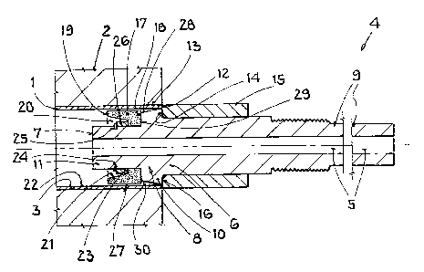
Figure 1 illustrates a device for forming a
peripherally closed hollow profiled element 1 by means
of fluidic internal high pressure, said device
containing an internal high pressure forming die 2, in
the forming space 3 of which the hollow profiled
element 1 is laid. The device contains, furthermore, at
least one axial plug 4 for sealing off the hollow
profiled element 1 on the end face. The axial plug 4
possesses a centrally running axial passage duct 5
which supplies pressure fluid to the hollow profiled
element 1 and which is connected at an end 6 facing
away from a hollow profiled element to a fluid high
pressure generation system conveying the pressure fluid
and which issues on the end face 7 of its plug head 8
penetrating into the hollow profiled element 1 in the
position of use. The plug head 8 capable of being
pushed into the hollow profiled element 1 is rigidly
connected to the remaining plug body 9 of the axial
plug 4 and is formed by an annular collar 10 shaped out
on the axial plug 4 and by a narrowed extension 11
adjoining said annular collar toward the end face 7 of
the head 8. The extension 11 is arranged centrally and
has the passage duct 5 passing through it. The axial
plug 4 has, furthermore, on its plug body 9, a radially
CA 02541427 2006-04-04
P036256/WO/1
g
peripheral stop which, in the position of use of the
axial plug 4, bears against the closing edge 12 of the
hollow profiled element end 13. The stop is formed here
by the end face 14 of a sleeve 15 screwed onto the plug
body 9 or fastened to the plug body 9 in another way.
For positioning the sleeve 15 during mounting on the
plug body 9, the end face 14 of said sleeve butts
against the rear side 16 of the annular collar 10.
The axial plug 4 carries a sealing body which is
designed as a sealing ring 17 pushed or slipped onto
the extension 11 of the plug head 8. In this case, the
sealing ring 17 is supported on the end face 18 of the
annular collar 10, said end face facing the hollow
profiled element 1. The sealing ring 17, spreadable in
a radially elastic manner, consists, for example, of an
elastomer or polyurethane. It has, on its end face 19
facing the hollow profiled element 1, a trough-like
depression 20, the peripheral wall 21 of which, by
means of the inflowing pressure fluid, undergoes the
spread within the hollow profiled element 1 until it
comes to bear sealingly against the inner wall 22 of
the hollow profiled element 1. The sealing ring 17,
furthermore, is supported on its depression bottom 23,
in the direction of the end face 7 of the plug head 8,
by means of a positioning ring 24 which is embedded in
a groove 25 of the extension 11. Moreover, a spacer
ring 26 is arranged between the positioning ring 24 and
the depression bottom 23 of the sealing ring 17. By
support by means of the positioning ring 24 and the
spacer ring 26, on the one hand, and by support on the
end face 18 of the annular collar 10, the sealing ring
17 is fixed axially to the plug head 8. The outside
diameter of the sealing ring 17 is selected such that
it lies with some play within the hollow profiled
element 1 in the position of use of the axial plug 4.
Furthermore, the outside diameters of the outside 27 of
the sealing ring 17 and of the margin 28 of the annular
CA 02541427 2006-04-04
P036256/WO/1
- 9 -
collar 10 are coordinated with one another such that
the latter projects peripherally beyond the sealing
ring 17 at at least one point in the radial direction.
That is to say, on the annular collar 10, there is at
least one point which is peripherally larger radially
than the entire outside 27 of the sealing ring 17. The
margin 28 of the annular collar 10, moreover, narrows
conically toward the end face 7 of the plug head 8,
thus forming, between the margin 28 of the inner wall
22 of the hollow profiled element I and the rear side
29, supported on the annular collar 10, of the sealing
ring 17, a small annular chamber 30 into which a part
quantity of the pressure fluid can briefly flow during
filling.
If, then, the hollow profiled element 1 is filled via
the passage duct 5 of the axial plug 7 with the
pressure fluid conveyed by the fluid high pressure
generation system, said pressure fluid flows in back
stroke into the depression 20 of the sealing ring 17,
with the result that, on account of the flow pressure
on the peripheral wall 21 of the elastic sealing ring
17, the latter spreads open until said wall is pressed
against the inner wall 22 of the hollow profiled
element 1. At the same time, as already mentioned, a
part quantity of pressure fluid flows past the sealing
ring 17 into the chamber 30, with the result that a
suction action occurs which assists the spreading of
the sealing ring 17 and consequently accelerates
sealing off during filling. The trough shape of the
depression 20 serves in this case for a better
conversion of the flow force of the inflowing pressure
fluid into a radial spreading movement of the
peripheral wall 21 of the sealing ring 17. If, then,
the hollow profiled element 1 is formed, the pressure
fluid is put under high pressure, with the result that
the peripheral wall 21 of the sealing ring 17 is
pressed to an extreme extent against the inner wall 22
CA 02541427 2006-04-04
P036256/WO/1
- 10 -
of the hollow profiled element 1, so that a sealing off
of the hollow profiled element 1 which is tight to
fluid high pressure is ensured outwardly.
A variant of the invention is shown in figure 2. In
this case, on the outside 27 of the sealing ring 17, an
annular bead 31 is formed, which projects radially
beyond the entire annular collar 10 of the plug 4 and
which is located near the end face 19 of the sealing
ring 17. The annular bead 31 may be injection-molded
onto the sealing ring 17 at a later stage or else be
shaped at the same time as the production of the
latter. On account of the annular bead 31, sealing off
is afforded even during the penetration of the axial
plug 4 into the hollow profiled element 1 before the
filling operation.
In a further variant of the invention according to
f figure 3 , contrary to the variants of f figures 1 and 2 ,
the outside 27 of the sealing ring 17 has incorporated
in it, near its end face 19 facing away from the
annular collar, a peripheral groove 32 which receives a
retaining ring 33 possessing a lower elasticity than
the sealing ring 17. If there is an oversize of the
retaining ring 33 with respect to the diameter of the
inner wall 22 of the hollow profiled element 1, the
retaining ring 33, preferably designed as a quad ring
or O-ring, assumes the provisional sealing function at
the commencement of the filling process. By virtue of
its contracting action on the sealing ring 17, the
retaining ring 33 gives the sealing ring 17 better
protection against being folded round and extruded into
the interspace between the plug head 8 and the inner
wall 22 of the hollow profiled element 1.
In contrast to the preceding exemplary embodiments, in
a variant of the invention according to figure 4, the
extension 11 has arranged on it a centering plate 34
CA 02541427 2006-04-04
P036256/WO/1
- 11 -
which peripherally projects radially beyond the sealing
ring 17 and the annular collar 10. The centering plate
34 precedes the sealing ring 17 toward the end face 7
of the plug head 8 and is fastened to the extension 11
by means of a central leadthrough 35, and, for
mounting, it is advantageous if, as here, the centering
plate 34 can be screwed onto the extension 11. So that
the introduced pressure fluid can flow onto the sealing
ring 17 in spite of the preceding centering plate 34,
with the result that the spreading movement can take
place, eccentric passage bores 36 are formed in the
circular centering plate 34.
In all the abovementioned variants, it is additionally
conceivable that one or more radial ducts, which issue
into the depression 20 of the sealing ring 17, branch
off from the passage duct 5 of the axial plug 4 at the
location of the depression 20. The peripheral wall 21
of the sealing ring 17 can thereby be acted upon, even
in an early phase of the filling operation, by pressure
fluid via the radial ducts as a result of a branch-off
and at the same time be spread open. Very early sealing
off is provided in this case.
By means of the device according to the invention,
which makes it possible for the hollow profiled element
1 to be sealed off outwardly without any axial force,
it is possible, as compared with seals not free of
axial force, to expand hollow profiled elements 1 by
means of internal high pressure and to calibrate them,
without shortening the component length, since the
axial force, which, when the hollow profiled element 1
is being sealed off, leads to a component-shortening
thickening of the hollow profiled element end, is
dispensed with. At the same time, creases are also
avoided, which normally arise due to the sealing force
fraction of the axial plugs in the case of seals not
free of axial force. Moreover, via the sleeve 15, an
CA 02541427 2006-04-04
P036256/WO/1
- 12 -
axial secondary push during forming may take place at
any time, as required, during the forming process.