Note: Descriptions are shown in the official language in which they were submitted.
CA 02541435 2006-04-04
WO 2005/038488 PCT/US2004/032247
MULTIPLE RADAR COMBINING FOR INCREASED RANGE, RADAR
SENSITIVITY AND ANGLE ACCURACY
BACKGROUND
s The invention relates generally to radar, and more particularly, to radar
systems
having multiple antennas.
In the field of radar systems technology, there continues to be a need for
improved
capability to handle potential lower cross section as well as longer range
targets. In the
past, this need has been met by developing larger, more sensitive (and thus
more costly)
o radars.
SUMMARY
The present invention features a technique for combining multiple radars for
increased sensitivity and range.
~ 5 In one aspect, therefore, a method of radar processing includes: radiating
a first
signal beam from an antenna of a first radar in the direction of a target;
radiating a second
signal beam from an antenna of a second radar in the direction of the target;
receiving
echo signals from the first signal beam at the first and second radars;
receiving echo
signals from the second signal beam at the first and second radars; processing
the echo
2o signals received at the first radar to produce first radar processed echo
signals; processing
the echo signals received at the second radar to produce second radar
processed echo
signals; and combining the first and second radar processed echo signals to
form an
aggregate value.
Particular implementations of the invention may provide one or more of the
25 following advantages. The present invention addresses a need for increased
range and
sensitivity to handle lower cross section and longer range targets as they
appear in the
future without having to build larger radars for them in the near term. The
increased
CA 02541435 2006-04-04
WO 2005/038488 PCT/US2004/032247
sensitivity is achieved by combining low sensitivity, lower cost radars with
minor
modification to achieve the higher sensitivity and increased range.
Other features and advantages of the invention will be apparent from the
following
detailed description and from the claims.
BRIEF DESCRIPTION OF THE DRAWINGS
FIG. 1 is a block diagram of a mufti-radar combining system.
FIG. 2 is a conceptual depiction of the mufti-radar combining system showing
the
paths of the transmit signal beams and corresponding echo signals for two
radars.
FIG. 3 is a block diagram of a portion of the system modified to combine
coherently the echo signals for the same carrier frequency and combine the
results
(different carrier frequencies) using video integration.
FIG. 4 is a block diagram of an exemplary digital implementation of the multi-
radar combining system.
~ 5 FIG. 5 is a table that shows sensitivity improvement for search and
tracking modes
based on different techniques of combining two radars.
Like reference numerals will be used to represent like elements.
DETAILED DESCRIPTION
2o Referring to FIG. 1, a mufti-radar combining system 10 that combines radars
to
achieve enhanced capability, in particular, increased range and sensitivity,
is shown. The
system 10 includes multiple radars 12, shown in the illustrated embodiment as
two radars
12a and 12b. Here radar 12b is the "master", although the roles could be
reversed. The
radars 12a and 12b each include a transmitter, shown as transmitter 14a and
transmitter
25 14b, respectively. The outputs of the transmitters 14a and 14b are
delivered to respective
2
CA 02541435 2006-04-04
WO 2005/038488 PCT/US2004/032247
antennas 16a, 16b for radiation in the form of a transmit beam directed at a
target
(indicated by reference numeral 18). In the illustrated embodiment, the
antennas 16a, 16b
are rotating antennas; however, a stationary antenna could also be used. The
antennas 16a,
16b collect echo signals received from the target, and the echo signals (which
may be
combined into monopulse receive signals) are processed by respective receivers
20a, 20b
to detect the presence of the target and determine its location in range and
in angle. In
radar 12a, a duplexer 22a coupled to the transmitter 14a, receiver 20a and
antenna 16a
allows the antenna 16a to be used on a time-shared basis for both transmitting
and
receiving. A duplexer 22b, coupled to the transmitter 14b, receiver 20b and
antenna 16b,
o provides the same functionality (as duplexer 22a) in radar 12b.
Still referring to FIG. 1, the receivers 20a and 20b include a low-noise
amplifier
("LNA") 23a and a LNA 23b, respectively. The LNA 23a (of receiver 20a) is
coupled to
down converters 24a-1 and 24a-2, and the LNA 23b (of receiver 20b) is coupled
to down
converters 24b-1 and 24b-2. The down converters 24a-1, 24a-2, 24b-1 and 24b-2
(more
s generally, down converters 24) perform RF-to-IF conversion. Each of the
receivers
includes a receiver exciter ("REX"), a REX 25a in receiver 20a and a REX 25b
in receiver
20b. The REX 25b of the master radar 12b (master REX) provides both transmit
carrier
frequencies f, and f2, with their modulations, and local oscillator signals
LO1 and LOZ
(indicated collectively by reference numeral 26), to radars 12a and 12b. In
the example
2o shown, with radar 12b serving as the master radar, REX 25a of radar 12a is
in "by-pass"
mode, that is, it does not operate as a REX but merely distributes within
radar 12a the
signals generated by REX 25b. In receiver 20a, the down converter 24a-1 and
the down
converter 24a-2 are connected to a signal processor 27a-l and a signal
processor 27a-2,
respectively. In receiver 20b, the down converter 24b-1 and the down converter
24b-2 are
3
CA 02541435 2006-04-04
WO 2005/038488 PCT/US2004/032247
connected to a signal processor 27b-1 and a signal processor 27b-2,
respectively. The
signal processors 27a-1, 27a-2, 27b-1 and 27b-2 (generally, signal processors
27) perform
filtering, possibly including pulse compression filtering. The signal
processors 27 are
further connected to envelope detectors, more specifically, signal processor
27a-l and
s signal processor 27a-2 are connected to envelope detector 28a-1 and envelope
detector
28a-2, respectively, while signal processor 27b-1 and signal processor 27b-2
are connected
to envelope detector 28b-l and envelope detector 28b-2, respectively. The four
envelope
detected signals are added (video integrated) by a combiner 30 and passed to a
threshold
detector 32 for detection. The threshold detector 32 is coupled to and
provides detection
information to other conventional radar system elements, e.g., a tracker 34
and a display
36, as shown.
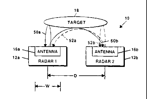
As indicated above, system 10 combines receive signals of radars 12a, 12b in a
manner that achieves greater sensitivity gain and increased range. Referring
now to FIG.
2 in conjunction with FIG. l, the radars 12a, 12b to be combined are
positioned in fairly
~ 5 close proximity to each other. The phase centers of the antenna 16a and
the antenna 16b
(in radar 12a and radar 12b, respectively), are spaced by a distance "D". The
distance D
is a flexible parameter. A small value for D may be selected to simplify the
processing of
the echo signals. If a larger distance is chosen, delays may be needed so that
the echo
signals can be added correctly (to within a fraction of a pulse width) during
processing.
2o Also, if coherent integration is used (f,=f2), the effects of
interferometric lobing become a
concern when there is too much spacing between the radars. If the distance D
is
somewhat larger than the width "W" of the antenna 16, then a large
interferometer
baseline is formed when coherent combining on receive is used (as discussed
shortly),
with the result that the angle accuracy will be improved, in some cases by an
order of
4
CA 02541435 2006-04-04
WO 2005/038488 PCT/US2004/032247
magnitude.
Referring again to FIG. 1, the rotation of the antennas of the multiple radars
are
synchronized by a synchronization signal provided by an azimuth servo 37b (in
radar 12b)
to an azimuth servo 37a (in radar 12a) so that the beams of the radars look in
the same
s direction, to within a fraction of a beamwidth. The radars nominally radiate
identical
transmit signal beams (e.g., beams 40 and 42 for radars 12a and 12b,
respectively) at the
same time. The beams could, however, be different. The carrier frequencies fl
and f2 are
different where incoherent transmit operation and incoherent receiver
combining is used.
The carrier frequencies f~ and fz will be the same if coherent transmit
operation and
o coherent receiver combining for all signals is desired, as discussed later.
When the carrier
frequencies f, and f2 are different, they may differ sufficiently so that they
do not interfere
with each other and can be separated from each other in the radar receivers,
yet are close
enough to allow the same phase shift commands for a phased array antenna.
Also, they
may differ sufficiently to provide frequency diversity, i.e., the echo
amplitudes are then
15 independent at the two frequencies. In addition, the use of different
carrier frequencies
helps to avoid interferometric lobing, which is not desirable during search
(and may not be
desirable for tracking, either, if the radars are too far apart). The echoes
of the transmitted
signals from both radars are received by both radars.
FIG. 2 shows the path of the echo signals for both radars. Still referring to
FIGS. 1
2o and 2, echoes from a transmit beam radiated by the antenna of radar 12a
towards the target
18 are received at radar 12a, as indicated by reference numeral SOa (echo
signals "el~"),
and are received at radar 12b, as indicated by reference numeral SOb (echo
signals "e12")
Similarly, the echoes of the transmitted signal from radar 12b are received at
radar 12a, as
indicated by reference numeral 52a (echo signals "e2~"), and are received at
radar 12b, as
CA 02541435 2006-04-04
WO 2005/038488 PCT/US2004/032247
indicated by reference number 52b (echo signals "e22"). These four echoes SOa,
SOb, 52a,
52b, are pulse compressed and pulse Doppler processed (if appropriate) in the
appropriate
signal processors 27 to produce processed echo signals s, ~ 54a, s~2 54b,
s2156a, s2z 56b,
respectively, as shown in FIG. 1. The four processed echoes are then envelope
detected
and video integrated to produce video integrated signals v~ l 57a, v12 57b,
v2, 58a and vZz
58b, respectively. These four signals are combined to produce an aggregate
value 59. It
will be understood from the figure that the receiver of radar 12a handles the
processing of
signals e> > SOa and e2, 52a to produce vi 1 57a and v2158a, respectively,
while the receiver
of radar 12b handles the processing of signals e12 SOb and e22 52b to produce
v,2 57b and
v22 58b, respectively.
In the embodiment illustrated in FIG. 1, the four echoes are combined
incoherently
in the radar receiver. Other techniques may be used to combine the echo
signals as well.
One example is shown in FIG. 3. Referring to FIG. 3, the combiner 30 of the
receiver is
suitably adapted to allow the processed signals having the same carrier
frequency, e.g., s"
~5 and s12, to be added coherently. Thus, s" and slz can be added coherently
by a first adder
60a, and sz, and sz2 can be added coherently by a second adder 60b. The
resulting sum
signals s~ i+s,z ("S~") and s21+s22 ("S2") each are envelope detected by
respective envelope
detectors 62a, 62b. The envelope detected values v~ and vZ are combined by a
third adder
60c to form the final, aggregate value 59.
2o Generally, for the search mode, it is found that coherent addition of the
type
described with reference to FIG. 3 does not provide any significant
improvement in
detectability over video integration (incoherent addition). This is the case
because the
phases of processed echo signals s" and sl2 (and s2~ and s22) are not known,
and so the
signals have to be added with a bank of adders having different relative phase
shifts, as
6
CA 02541435 2006-04-04
WO 2005/038488 PCT/US2004/032247
will be described shortly. For the track mode, coherent addition can provide
better SNR.
The processed echo signals may be combined using different techniques when the
carrier frequencies f~ and fz are equal as well. For example, the four
processed echo
signals may be combined coherently (track mode), or using a combination of
coherent and
incoherent integration (for track or search mode also). When fl = f2, it is
only necessary to
have one mixer per radar. In the illustrated embodiment of FIG. 1, for the
case of f,= f2,
only one pair of mixers, for example, 24a-1 and 24b-1 (or, alternatively, 24a-
2 and 24b-2),
need be used. As discussed later, f~ would be set equal to f2 generally for a
track mode
only.
The potential advantage of using coherent integration is that of providing
improved
sensitivity (about another 3 dB to about 9 dB) for the track mode. This
improved
sensitivity is realized because of the coherent addition that can result in
beams from radars
12a and 12b at the target for f,=f2 when the signals from radars 12a and 12b
are
transmitted simultaneously. An interferometric pattern is produced on
transmit. If the
15 phase centers of the two radars are not known to a fraction of a
wavelength, then more
than one simultaneous transmission of the signals from radaxs 12a and 12b will
be needed
with different relative phase shifts between the signals for each transmission
to ensure
coherent addition at the target (or worded differently, to ensure that the
target is near the
peak of transmit interferometric peak). First a 0° relative phase shift
would be tried. If
2o the target is not detected (or the SNR is not as large as expected), then a
180° relative
phase shift would be used. If the target is still not detected (or the SNR not
large enough),
a 90° relative phase shift could be used, followed finally by a
270° relative phase shift.
On receive, because the phases of the signals out of the radars 12a and 12b
will not
generally be known, the coherent combining will be performed using a bank of
parallel
CA 02541435 2006-04-04
WO 2005/038488 PCT/US2004/032247
channels each adding the two signals with a different relative phase shift.
For example,
eight phase shifts from 0° to 315° in steps of 45° could
be used. After the best relative
phase shift for receive was determined out of the eight possible phase shifts,
the signals
could be reprocessed with smaller phase steps to determine which gives the
best SNR, so
as to eventually achieve 9 dB improvement in SNR over that obtained with one
radar in
the track mode.
If the phase centers of the two radars were known to a fraction of a
wavelength, it
would not be necessary to use multiple transmissions with different phase
shifts to get the
signals from the two radars to add coherently at the target, i.e., to put a
transmit
interferometric lobe on the target. Instead, the phase shift needed to put a
transmit and
receive interferometric lobe on the target would be determined from knowledge
of the
location of the target to a fraction of a beamwidth. The target angle
determination is
obtained from the normal monopulse channel signals from the radars operated
with f~~f2.
In this case, the standard monopulse outputs of radars 12a and 12b would be
processed in
~ 5 the same way as described above (with reference to FIG. 3) for the sum
signal outputs, but
now to estimate the target angle. The coherent addition on transmit and
receive can be
further improved if defined by using the initial phase shifts for transmit and
receive
obtained from the monopulse measurements and then searching for better phase
shifts for
transmit and receive.
2o With fl=f2 it is possible to avoid having an interferometric pattern on
transmit by
transmitting the signals from radars 12 and 12b sequentially in time so as not
to overlap in
time on transmit or receive. The echo signals can then be added incoherently
when
appropriately delayed on receive. The sequential transmissions eliminate the
need for two
receivers in each radar. The improvement in sensitivity achieved with this
technique is
CA 02541435 2006-04-04
WO 2005/038488 PCT/US2004/032247
about 6 dB.
Once the target is detected, it is possible to estimate that target's azimuth
(or
elevation) angle very accurately. For f~~fz, it is possible to determine the
target's location
in angle to a fraction of a receive interferometric lobe width. This
determination can be
made by measuring the phase of s, ~ relative to sIZ and, likewise, szl
relative to szz.
Knowing these phases provides a very accurate estimate of the target angle,
specifically to
a fraction of a receive interferometric lobe width, which is much narrower
than the width
of the beams of each radar. The ambiguity as to which lobe the target is on is
eliminated
by using a normal monopulse measurement obtained with f~~fz as described
above.
o For fl=fz, the target angle is estimated accurately by measuring the phase
between
the signals out of receivers 22a and 22b independent of whether the signals
are transmitted
from radars 12a and 12b simultaneously or sequentially.
Other implementations of the radars 12a, 12b are possible. While the block
diagram of FIG. 1 is intended to be conceptual in nature, it depicts an all
analog
~ 5 implementation for the radars 12a, 12b. It will be understood, however,
that the radar
receiver can be designed for digital signal processing, as shown in FIG. 4.
Referring now to FIG. 4, the system 10 includes a digital signal processor 70
that
receives echo signals from each of the down converters 24. In the exemplary
digital
processing implementation of FIG. 4, the signals correspond to in-phase ("I")
and
2o quadrature ("Q") channels. The digital signal processor 70 performs
digitally those
functions performed by units 27, 28 and 30 of system 10 as depicted in FIG. 1.
The output
of the digital signal processor 70, that is, the aggregate value, can be
provided to threshold
detector 32, as before.
Although the digital signal processor 70, like the units 27, 28 and 30, can be
CA 02541435 2006-04-04
WO 2005/038488 PCT/US2004/032247
separate from the radars 12a, 12b, this circuitry could reside in one or both
of the radars.
If included in both radars, only the digital signal processor 70 in one radar
operating as the
master would be used during operation. The same can be said of the threshold
detect 32,
tracker 34 and display 36. In FIG. 4, as in FIG. 1, radar 12b is represented
as the master.
s Any digital signal processing, threshold detect, tracking and display
capability in radar
12a, to the extent that it may exist, has been omitted from the figure for
simplification.
While only two radars are shown in the system examples of FIGS. 1 and 4, it
will
be appreciated that the multi-radar combining concept embodied therein can be
extended
to more than two radars. Also, although the radars 12a, 12b are described as
rotating
antennas, the technique described herein also applies to radars that use non-
rotating phased
arrays.
FIG. 5 shows a table that provides the Signal-to-Noise Ratio (SNR) sensitivity
improvement (in dB) for different techniques of combining two radars. For a
non-
fluctuating target, the sensitivity gain of the combined radars (relative to a
single radar) is
~ s approximately 6dB for searches regardless of whether coherent or
incoherent integration is
used (on transmit and/or receive). For track mode, when coherent integration
is used on
transmit and the frequency is the same for both radars (that is, f~= f2), the
strength of the
signal on the target is greater by 3 dB so that the SNR is now 3 dB higher for
a total gain
of 9 dB over that for a single target.
2o For the case of a fluctuating target (Swerling-II type), it is assumed that
the two
radars being combined as described above use carrier frequencies that differ
sufficiently to
provide frequency diversity. For a single look Pd of 90%, therefore, the
resultant increase
in sensitivity is 8.7 dB better than that of a single radar that does not use
frequency
diversity.
CA 02541435 2006-04-04
WO 2005/038488 PCT/US2004/032247
Other embodiments are within the scope of the following claims.
What is claimed is:
11