Note: Descriptions are shown in the official language in which they were submitted.
CA 02542470 2006-04-12
DESCRIPTION
DISC-SHAPED TOOL
TECHNICAL FIELD
The present invention relates to a disc-shaped tool such as a
circular saw blade used for processing whose material is not limited to
any particular one, but applicable for wood, woody material, plastic,
iron/steel material, nonferrous metal or the like, more particularly to
a disc-shaped tool in which a vibration accompanying cutting or a buckling
is unlikely to occur.
BACKGROUND ART
Conventionally, a variety of forms of slits, which are an
elongated hole formed in a base metal of a circular saw blade, have been
proposed as this kind of the disc-shaped tool. For example, Japanese
Patent Application Publication No.46-21356, Japanese Utility Model
Application Publication No.5-18010, European Patent No.0640422A1, West
Germany Patent No. 19648129A1 have disclosed this kind of the circular saw
blades. It has been well known that providing with such a slit increases
the critical revolution number of the circular saw blade and further
filling the slit with resin makes noise and vibration which affects the
quality of a cut face adversely, unlikely to occur. The critical
revolution number is a revolution number which generates buckling in a
circular saw blade and generally the circular saw blade is used at a
revolution number below the critical one. However, how the arrangement
and the entire shape of the slit are related to the stiffness and the
critical revolution number of the circular saw blade and how they affect
1
CA 02542470 2006-04-12
the durability and suppression of vibration have not been clarified and
therefore, it is not clear whether or not a slit having an appropriate
shape is formed at an appropriate position.
The inventors analyzed in detail about how the arrangement and the
entire shape of the slit formed in the disc-shaped tool affect the
stiffness of the disc-shaped tool, the critical revolution number and
vibration, confirmed its analysis result based on specific experiment
results so as to investigate those results and then reached the present
invention based on those results.
The present invention intends to solve the above-described
problem and provide a disc-shaped tool which has a high stiffness and high
critical revolution number and ensuring a high durability and is unlikely
to generate a vibration accompanying a cutting work by specifying the
arrangement position and condition of the slits.
DISCLOSURE OF THE INVENTION
The feature of the configuration of the present invention to
achieve the above-described object exists in a disc-shaped tool in which
a plurality of virtual regions formed such that it is surrounded by two
radius lines extending from a rotation center of a base metal and two
concentric circles on the base metal disposed around the rotation center
is disposed continuously in a circumferential direction on the
disc-shaped base metal while a single slit is provided in each virtual
region so that it makes contact with all of the two radius lines and two
concentric circles, wherein a central angle formed by the two radius lines
is equal to or less than 900, the number of the virtual regions is 4 to
2
CA 02542470 2010-07-20
76996-7
24, the concentric circle located in a center of an interval of two concentric
circles
forming the virtual region is in a range of 0.6r to 0.8r with respect to the
rotation
center of the base metal when a maximum gullet bottom radius of the base metal
is r, an overlapping of the virtual regions continuously adjoining each other
is in a
range of 0 to 12 in terms of the central angle around the rotation center, a
minimum neighborhood distance between the adjoining slits is equal to or more
than 0.05r, and a ratio of a length of an arc of the central concentric circle
in each
virtual region with respect to the interval of the two concentric circles in
the virtual
region is 3 to 6, and each of the plurality of virtual regions has the same
shape.
According to one embodiment of the present invention, if the
maximum gullet bottom radius of the base metal is assumed to be r when a
circular saw blade having the slit 14 is taken as a disk-shaped tool, the
relation
between the stiffness R (kgf/mm) and the critical revolution number min-Ncr
(rpm)
of the disc-shaped tool about the position in the radius direction of the
central
concentric circle located in the center of the two concentric circles forming
the
virtual region was obtained by finite element model (FEM) analysis using a
computer. As the FEM analysis software, ANSYS (manufactured by ANSYS
Japan) was used. As reference values of the stiffness R and the critical
revolution
number, the stiffness R of 0.59 kgf/mm or more and critical revolution number
of
4,430 rpm or more, which are values of a circular saw blade having no slit in
a
conventional base metal as shown in FIG. 8 (having four slits on the outer
periphery) were employed. As a result, in the case where the position of the
central concentric circle was over 0.6r, the stiffness R was higher than the
reference value.
3
CA 02542470 2010-07-20
76996-7
In the case where the position of the central concentric circle was below
0.8r, the critical revolution number was higher than the reference value.
Therefore, the position of the central concentric circle was specified
to be in a range of 0.6r to 0.8r.
Next, the ratio of the length of an arc in the virtual region of
the central concentric circle with respect to the interval of the two
concentric circles in the virtual region was obtained in the case where
the position of the central concentric circle was 0.8r and 0.6r. When
the position of the central concentric circle is 0.8r, the ratio of the
critical revolution number needs to be over 3 although there is no problem
in the stiffness R. In the case where the position of
the central concentric circle is 0.6r, the ratio of the stiffness R needs
to be below 6 and there is no problem in the critical
revolution number. As a result, the ratio of the length of the arc with
respect to the interval of the concentric circles was specified to be in
a range of 3 to 6.
Next, an overlapping range of continuously adjoining virtual
regions was obtained. In case where the position of the central concentric
circle is 0.7r, the stiffness R has no problem if the overlapping angle
is equal to or less than 12 and the critical revolution number is equal
to or more than -1 . Further, considering- an analysis
result in the case where the position of the central concentric circle
is 0.6r and 0.8r, the overlapping angle was specified to be in a range
of 00 to 12 .
In the meantime, if the central angle formed by the two radius
lines exceeds 90 , the stiffness of the circular saw blade drops so that
4
CA 02542470 2006-04-12
four or more virtual regions are required. Even if the quantity of the
virtual regions exceeds 24, the characteristic does not change so much,
thereby increasing cost for forming the slit. Further if the minimum
neighborhood distance of adjoining slits is smaller than 0.05r or smaller
than 0.08r under a specific severe condition, an interval between the
slits is likely to be short-circuited, so that there is a fear that the
circular saw blade may be damaged easily.
Further, according to one embodiment of the present invention, the
plurality of virtual regions can be formed into the same shape. By forming
the plurality of virtual regions into the same shape, the symmetrical
property in the rotation direction of the circular saw blade is secured,
thereby raising productivity and improving visual aesthetic sense.
Further, not only the plurality of virtual regions can be formed
into the same shape but also the slits formed in the plurality of virtual
regions can be formed into the same shape. Because the plurality of virtual
regions is formed into the same shape and the slits formed in the plurality
of virtual regions are formed into the same shape, the symmetrical
property in the rotation direction of the circular saw blade is secured,
thereby further raising productivity and improving visual aesthetic
sense.
According to one embodiment of the resent invention, because the
arrangement position and condition of the slits to be provided in the
disk-shaped tool such as the circular saw blade are specified concretely,
the present invention can suppress generation of noise and vibration which
affects the quality of a cut face adversely while maintaining stiffness
and critical revolution number equal to or higher than a conventional
CA 02542470 2006-04-12
circular saw blade and securing a high durability. Further, because the
plurality of virtual regions is formed into the same shape and the slits
in the respective virtual regions are formed into the same shape, the
symmetrical property in the rotation direction of the disk-shaped tool
is secured, thereby raising productivity and improving a visual aesthetic
sense.
BRIEF DESCRIPTION OF THE DRAWINGS
FIG. 1 is a side view showing a circular saw blade according to
an embodiment of the present invention;
FIG. 2 is partially enlarged side view showing a major portion of
the circular saw blade in enlargement;
FIG. 3 is a graph showing a relation between a position in a radius
direction of a center concentric circle located in a center of an interval
between two concentric circles forming a virtual region of the circular
saw blade, a stiffness value R (kgf/mm) and critical revolution number
min-Ncr(rpm) of the circular saw blade;
FIG. 4 is a graph showing a relation between a ratio of an arc
length (the position of the central concentric circle is 0.8r) within the
virtual region of the central concentric circle with respect to the
interval of the two concentric circles of each virtual region, the
stiffness R and the critical revolution number min-Ncr of the circular
saw blade;
FIG. 5 is a graph showing a relation between the ratio of an arc
length (the position of the central concentric circle is 0.6r) within the
virtual region of the central concentric circle with respect to the
6
CA 02542470 2006-04-12
interval of the two concentric circles of each virtual region, the
stiffness R and the critical revolution number min-Ncr of the circular
saw blade;
FIG. 6 is a graph showing a relation between an overlapping angle
of the continuously adjoining virtual regions, the stiffness R and the
critical revolution number min-Ncr of the circular saw blade;
FIG. 7 is a side view showing a circular saw blade according to
a modification; and
FIG. 8 is a side view showing a conventional circular saw blade.
BEST MODE FOR CARRYING OUT THE INVENTION
Hereinafter, an embodiment of the present invention will be
described with reference to the accompanying drawings. FIG. 1 is a side
view showing a circular saw blade for cutting aluminum according to the
embodiment of the present invention. FIG. 2 is a partially enlarged side
view showing a major portion of the circular saw blade. The circular saw
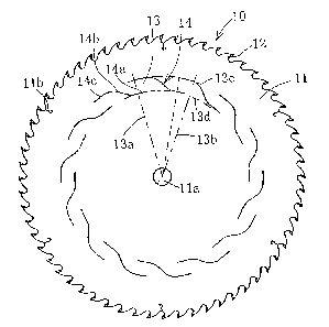
blade 10 is provided with a disc-shaped base metal 11 and teeth 12. The
teeth 12 are protruded outwardly from plural positions continuously
disposed at an equal interval on an outer periphery of the base metal 11.
The base metal 11 has a central shaft hole ila and outer periphery slits
lib which extend slightly from the outer periphery of each gullet bottom
at six positions disposed at an equal interval in a circumferential
direction while rounded in the shape of an arc internally. The base metal
11 contains fourteen virtual regions 13 which are formed by two radius
lines 13a, 13b extending from a rotation center thereof and two concentric
circles 13c, 13d on the base metal formed around the rotation center, the
7
CA 02542470 2006-04-12
virtual regions 13 being provided continuously around the rotation center.
Each of the virtual regions 13 contains a single slit 14 which makes
contact with the two radius lines 13a and 13b and the two concentric
circles 13c and 13d, the single slit 14 being formed by laser processing
or the like.
As for the slit 14, a central angle formed by the two radius lines
around the rotation center is substantially 34 and is divided in terms
of the central angle into three sections, forward small-diameter portion
14a, central inclined portion 14b and rearward large-diameter portion 14c,
which are formed continuously as viewed from the forward side in the
rotation direction. A radius of the forward small-diameter portion 14a
is substantially 0. 64r and a radius of the rearward large diameter portion
14c is substantially 0.76r. Here, "r" indicates a radius of a maximum
gullet bottom radius of the base metal 11, that is, a radius from the center
of the base metal to a root of the tooth 12. The central inclined portion
14b is disposed obliquely between the forward small-diameter portion 14a
and the rearward large-diameter portion 14c and a joint portion which is
a boundary between the forward small-diameter portion 14a and the rearward
large-diameter portion 14c is formed into an arc shape. As a consequence,
the position of the central concentric circle 13e in the radius direction
(position in the radius direction) located in the center of an interval
between the two concentric circles 13c and 13d forming the virtual region
13 is 0.7r.
Overlapping of the continuously adjoining virtual regions 13 has
a central angle Os of about 8.29 which is an angle around the rotation
center. The minimum neighborhood distance between the adjoining slits 14
8
CA 02542470 2006-04-12
is about 0. 1r. I The ratio (slit horizontal to vertical ratio) of the length
of an arc of 0. ~415r within the virtual region 13 of the central concentric
circle 13e with respect to an interval between the two concentric circles
in each one of the virtual regions 13 of 0.104r is about 3.99.
According to the embodiment having the above-described structure,
the arrangement position and condition of the slit 14 to be provided in
the circular saw blade 10 are specified within the above-described numeric
range. As a result, the embodiment can raise the durability and suppress
generation of noise and vibration affecting the quality of a cut face
adversely while holding a stiffness and critical revolution number
characteristic which are equivalent to or higher than a conventional
circular saw blade having no slit in its base metal. Further, because
the slit 14 formed within each one of the virtual regions 13 is formed
into the same shape as well as the shape of each of the plurality of virtual
regions 13 is formed into the same shape, a symmetrical property in the
rotation direction of the circular saw blade 10 is secured and
productivity and visual aesthetic sense are intensified. However, the
plurality of virtual regions does not always need to have the same shape
or the shape of the slit does not always need to be identical.
Next, a modification of the above embodiment will be described.
A circular saw blade 20 of the modification is so constructed that
as shown in FIG. 7, four teeth 22 arranged at an equal interval of one
pitch continuously and a tooth 23 shifted by a 1.5 pitch from this are
projected as a combination outwardly in the diameter direction from a
plurality of positions of the outer periphery of a disc-shaped base metal
21. The quantity of the teeth 22 arranged at the equal interval may be
9
CA 02542470 2006-04-12
three or five although it is most preferred to be four. The configuration
of the slit 24 formed on the base metal 21 and the virtual region (not
shown) are the same as the slit 14 and the virtual region 13 of the above
embodiment.
The circular saw blade 20 of the modification secures the same
effect as the above embodiment by providing with the predetermined slits
24 and it has been made evident that including one tooth 23 shifted in
pitch in the plurality of teeth 22 arranged at the equal pitch is very
effective for cutting a metal pipe such as steel and iron.
Next, specific experiments of the above-described embodiment and
the modification will be described.
As the test piece, test pieces 1 for cutting aluminum material of
the embodiment and test pieces 2 for cutting steel/iron of the
modification were prepared. The test pieces 1 are circular saw blades
based on three kinds of specifications (outside diameter X tooth
thickness X base metal thickness X central hole diameter X number of
teeth) to (3 having the above-described slit structure as shown in Table
1 below, these circular saw blades having six outer periphery slits
extending by 10 mm from the outer periphery to the rotation center. The
cutting condition is a revolution number N and a feeding speed F, which
is different for each one of the circular saw blades. An object material
to be cut is aluminum extruded material A6063.
The test pieces 2 are circular saw blades based on two kinds of
specifications (1), (2 having the above described slit structure (outside
diameter X tooth thickness X base metal thickness X central hole diameter
X number of teeth) and have no slits on the outer periphery. The cutting
CA 02542470 2006-04-12
condition is a revolution number N and a feeding speed F, which are common.
The object materials to be cut are respective kinds of steel pipes, STKM13C,
15A, and 15B.
[Table 1]
Test pieces l(for aluminum) Test pieces 2(for the pipe)
Position in radius 0.7 times of 0.7 times of
direction 0.6^-0.8 gullet bottom radius gullet bottom radius
Overlapping angle 6.29 6.29
0 ^-12
Slit horizontal to
vertical ratio 3 ^-6 times 3.76 times 3.76 times
~D 405 X T2. 0 X t 1. 5 X (D 25. 4 X 144Z (D l 285 X T2. 0 X t 1. 75 X (D 40 X
80Z
Specifications of (q) 6 10 X T3. 3 X t2. 7 X (D 40X138Z (2 )285XT1.6Xt1.3X (P
40X80Z
the circular saw blades
(I q) 650 X T3. 5 X t3. 0 X (D 40X138Z * No outer periphery slits
* Outer periphery slits 10mmX6
N=4, 500rpm, F=5m/min Both (1),
Cutting condition N=3,000rpm, F=5m/min N=130rpm, F=0.52m/min
03 N=2, 830rpm, F=5m/min
Durability
(compared with a conventional About 1.5 times About 1.5 times
circular saw blade)
Respective kinds of shapes made of STKM13C c 20.38 X t3
aluminum extruded materials A6063
Object materials to be cut STKMI5A D 22.38 X t2
STKMI5B(D 51.2Xt3.1
The result of the experiment shows the durability of both the test
pieces 1 and 2 is raised by about 1.5 times as compared with a conventional
circular saw blade shown in FIG. 8. That is, this is a result produced
because the stiffness and the critical revolution number of the test
11
CA 02542470 2006-04-12
pieces are raised as compared with those of a conventional product.
Because the critical revolution number is raised, vibration accompanying
a cutting work is suppressed more as compared with the conventional
product, thereby suppressing generation of noise and raising the
processing accuracy on a cutting face.
Although in the above embodiment, the gullet bottom of the
circular saw blade is formed uniformly, the gullet bottom may be ununiform
and in that case, as the value of r, the maximum gullet bottom radius is
used. In the above-described embodiment, generation of vibration is
intended to be suppressed while maintaining the stiffness and critical
revolution number appropriately by specifying the slit to be provided in
the circular saw blade. Such a slit specifying condition is not restricted
to the circular saw blade but applied to other disc-shaped rotation
cutting tool, for example, disc cutting grinding stone, circular slitter
knife and the like.
INDUSTRIAL APPLICABILITY
The present invention is very advantageous for design or the like
of a disk-shaped tool in that the arrangement position and the entire shape
of the slit formed in the disc-shaped tool is defined, thereby raising
the stiffness and the critical revolution number of the disc-shaped tool,
such that generation of vibration can be suppressed.
12