Note: Descriptions are shown in the official language in which they were submitted.
CA 02542480 2006-04-13
WO 2005/037517 PCT/US2004/034238
APPARATUS AND METHOD FOR HOLDING MATERIALS
FOR THE FORMING AND JOINING THEREOF
Field of the Invention
[0001] The present invention relates to systems for holding and aligning a
first
sheet material and a second sheet material for the joining thereof. More
particularly,
the present invention relates to a method and apparatus for holding a first
sheet
material and a second sheet material that utilizes a vacuum arrangement for
holding
the first sheet material in place during the alignment of the second sheet
material
thereto and during the joining of the first sheet material to the second sheet
material.
Description of the Relevant Art
[0002] One of the earliest operations required in the history of automobile
assembly was the joining of an inner panel to an outer panel to form any of a
variety of
body parts, including doors, engine hoods, fuel. tank doors and trunk lids,
all referred to
as "swing panels" which encase the vehicle frame. Known machines for the
forming
and joining of sheet materials include the press-and-die set, the tabletop and
the roller-
forming tool, the latter being the most-recently introduced device.
[0003] An unfortunate feature of joining materials is that the sheets tend to
become
misaligned with each other before or during the joining operation. Certain
efforts have
been undertaken to overcome this problem.
[0004] One known effort employed to prevent the skidding of one sheet relative
to
the other has been to apply an upper pressure ring from above the sheet
materials,
CA 02542480 2011-06-10
thereby pinching the upper and lower sheets between the upper pressure ring
and the lower nest
member. This practice leads to the consumption of much of the workspace above
the sheet
materials. In addition, the use of the upper pressure ring requires a high-
powered overhead
device to effect operation. All considered, the use of the upper pressure ring
is costly and
inconvenient.
[0005] An additional known practice to prevent skidding of two sheets during
joining is to align
the two sheets relative to one another from the side using side gauges. This
operation, while
offering certain advantages over the use of the upper pressure ring in terms
of cost, space and
equipment, does a poor job of controlling movement of the sheet materials. The
use of gauges
also leads to defacing of the sheet material through scratching during loading
and unloading of
the sheet material.
Importantly, during operation, the gauges interfere with the travel of the
forming tool.
In some instances, if the gauges are spring-loaded, the rolling tool may be
shocked and may
suffer a pressure bounce when struck.
[0006] An additional practice has been to simply position one sheet above the
other without
holding, this latter approach clearly being the least desirable.
[0007] Accordingly, prior approaches to solving the problem of providing a
method and
apparatus for forming and joining two sheet materials together while
restricting movement of the
sheets relative to one another have failed to overcome the problem.
SUMMARY OF THE PRESENT INVENTION
According to an aspect of the present invention, there is provided a sheet
metal forming machine
cell for press hemming and roller hemming of a first sheet metal material to a
second sheet metal
material, the first sheet metal material having a surface contour, the sheet
metal forming machine
cell comprising: a) a lower nest for holding the first sheet metal material,
the lower nest
including a frame and an upper surface, the upper surface including a vacuum
pad and a
material-contacting portion, the material-contacting portion being defined to
substantially
2
CA 02542480 2011-06-10
cooperate with the surface contour of the first sheet metal material, the
vacuum pad having an
elongated channel formed therein and being composed of an elastic or semi-
elastic polymerized
material, its upper surface being located adjacent the material-contacting
portion and defined to
cooperate with the surface contour of the first sheet metal material; and b) a
vacuum system in
fluid connection with the elongated channel of the vacuum pad of the upper
surface of the lower
nest for selectively evacuating the elongated channel and holding the first
sheet metal material
during the joining of the first sheet metal material to the second sheet metal
material.
According to another aspect of the present invention, there is provided a
sheet metal forming
machine cell for press hemming and roller hemming a first sheet metal material
to a second sheet
metal material, the machine cell comprising: a) a lower nest for holding the
first sheet metal
material, the lower nest including a vacuum pad for receiving the first sheet
metal material, the
vacuum pad having an elongated channel formed therein and being composed of an
elastic or
semi-elastic polymerized material, its upper surface being located adjacent a
material-contacting
portion of the lower nest and defined to cooperate with a surface contour of
the first sheet metal
material; and b) a vacuum system in fluid connection with the elongated
channel of the vacuum
pad of the lower nest for selectively evacuating the elongated channel and
holding the first sheet
metal material during the joining of the first sheet metal material to the
second sheet metal
material.
According to yet another aspect of the present invention, there is provided a
sheet metal forming
machine cell for press hemming and roller hemming of a first sheet metal
material to a second
sheet metal material, the first sheet metal material having a surface contour,
the machine cell
comprising: a) a lower nest for holding the first sheet metal material, the
lower nest including a
frame, a material contacting portion defined to substantially cooperate with
the surface contour
of the first sheet metal material and a vacuum pad, the vacuum pad being
composed on an elastic
or semi-elastic polymerized material and including at least one elongated
channel, its upper
surface being located adjacent the material-contacting portion and defined to
substantially
cooperate with the surface contour of the first sheet metal material; b) an
upper gate for holding
2a
CA 02542480 2011-06-10
the second sheet metal material; and c) a vacuum system in fluid connection
with the at least one
elongated channel of the vacuum pad for selectively evacuating the elongated
channel and
holding the first sheet metal material during the joining of the first sheet
metal material to the
second sheet metal material, the vacuum system including a plenum and at least
one fluid line
connecting the plenum to the at least one elongated channel, the vacuum system
further
including a fluid line for fluidly connecting the plenum to a vacuum source.
According to a further aspect of the present invention, there is provided a
sheet metal forming
machine cell for press hemming and roller hemming a first sheet metal material
to a second sheet
metal material, the first sheet metal material having a surface contour, the
machine cell
comprising: a) a frame having a plurality of sidewalls, the frame having a
first material
contacting surface; b) a vacuum pad supported by the frame adjacent the first
material contacting
surface, the vacuum pad having at least one elongated channel defined therein
and a second
material contacting surface; and c) a vacuum source; d) a fluid line coupling
the at least one
elongated channel to the vacuum source; and e) a forming tool being operative
to effect forming
of the first sheet metal material.
According to yet a further aspect of the present invention, there is provided
a method for press
hemming and roller hemming a first sheet metal material to a second sheet
metal material, the
method comprising: a) forming a frame having a material contacting portion and
an elongated
vacuum chamber adjacent the material contacting portion and having a vacuum
source in
communication with the elongated vacuum chamber; b) locating the first sheet
metal material on
the frame; c) locating the second sheet metal material adjacent the first
sheet metal material; d)
clamping the first sheet metal material to the frame by operating the vacuum
source to
selectively evacuate the elongated vacuum chamber and hold the first sheet
metal material; and
e) operating a forming tool on at least one of the first sheet metal material
or the second sheet
metal material.
2b
CA 02542480 2011-06-10
[0008] It is thus the general object of the present invention to provide a
method and apparatus
that overcomes the problems of known techniques for forming and
2c
CA 02542480 2006-04-13
WO 2005/037517 PCT/US2004/034238
joining a first sheet material to a second sheet material to create a swing
panel for an
automobile.
[0009] It is a particular object of the present invention to provide a machine
cell for
forming and joining a first sheet material to a second sheet material which
provides a
definite method for aligning and securing a first panel to the lower nest and
for aligning
and securing the second panel to the first panel.
[0010] A further object of the present invention is to provide such a machine
cell
which utilizes an array of crowders to align the first panel on the lower
nest.
[0011] Yet another object of the present invention is to provide such a
machine cell
which utilizes a vacuum system to securely hold the first panel to the lower
nest.
[0012] Still a further object of the present invention is to provide such a
machine
cell which utilizes an upper gate for aligning and holding the second panel
relative to
the first panel.
[0013] Another object of the present invention is to provide such a machine
cell
which is efficient, cost-effective, and flexible enough to accommodate panels
of
various sizes, shapes, and contours.
[0014] These and other objectives are achieved by the provision of a machine
cell
which includes an upper gate and a lower nest. The lower nest includes an
upper
surface which has at least one channel defined in the upper surface. A vacuum
source is fluidly connected to the channel(s).
[0015] A pair of married sheet materials A, B are approximated onto the lower
nest. The first sheet material A is then precision positioned by means of
crowders.
The upper gate thereafter aligns the second sheet material B with respect to
the first
3
CA 02542480 2006-04-13
WO 2005/037517 PCT/US2004/034238
sheet material A by alignment pins. The first sheet material A is held in
place by a
vacuum applied to its under side by way of the channel. Thus held in place, a
forming
operation may be effected for joining the first sheet material A to the second
sheet
material B.
[0016] These and other objectives are accomplished by the provision of a
machine
cell for forming and aligning a first sheet material to a second sheet
material as set
forth hereinafter.
BRIEF DESCRIPTION OF THE DRAWINGS
[0017] The present invention will be more fully understood by reference to the
following detailed description of the preferred embodiments when read in
conjunction
with the accompanying drawings, in which like reference characters refer to
like parts
throughout the views, and in which:
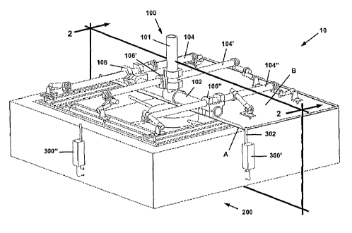
[0018] Figure 1 is a perspective view of the preferred embodiment of the
present
invention;
[0019] Figure 2 is a sectional view taken along lines 2-2 of Figure 1;
[0020] Figure 3 is a perspective view of the upper gate of the present
invention;
[0021] Figure 4 is a sectional view of a spring plunger according to the
present
invention;
[0022] Figure 5 is a top plan view substantially illustrating a sample inner
sheet
material or the support structure that forms the inner part of the resulting
joined
component; and
[0023] Figure 6 is a perspective view substantially illustrating the top of
the lower
nest member.
4
CA 02542480 2006-04-13
WO 2005/037517 PCT/US2004/034238
DETAILED DESCRIPTION OF A PREFERRED
EMBODIMENT OF THE PRESENT INVENTION
[0024] The drawings disclose the preferred embodiment of the present
invention.
While the configurations according to the illustrated embodiment are
preferred, it is
envisioned that alternate configurations of the present invention may be
adopted
without deviating from the invention as portrayed. The preferred embodiment is
discussed hereafter.
[0025] With reference first to Figure 1, the preferred embodiment of a machine
cell,
generally referred to as 10, is illustrated in a perspective view. The machine
cell 10
includes an upper gate 100 and a lower nest 200. It should be understood that
the
configuration of the machine cell 10 as illustrated is preferred, but is not
to be
interpreted as limiting as other configurations conceivable to those skilled
in the art
may also be suitable.
[0026] The present invention serves to hold two portions of sheet material so
that a
joining process may be undertaken without the sheet material portions being
caused to
shift or otherwise move out of position. The two portions of sheet material
include a
first sheet material A and a second sheet material B. The two sheets A and B,
in a
combination resulting from joining and forming becomes an integrated
component, of
which the first sheet material A is the outer part or the skin and the second
sheet
material B is the inner part or the support structure. (This latter material
is illustrated,
by way of example, in Figure 5, discussed below.) As illustrated, the first
sheet
material A and the second sheet material B have a generally square
configuration
CA 02542480 2006-04-13
WO 2005/037517 PCT/US2004/034238
resulting in a generally square-shaped integrated component. However, it is to
be
understood that other shapes may be suitable for use in the present invention.
[0027] In brief, the married sheet materials A, B are approximated onto the
lower
nest 200. The first sheet material A is then precision positioned by means of
crowders, which will be discussed below primarily in relation to Figure 1.
Thereafter
the upper gate 100 aligns the second sheet material B with respect to the
first sheet
material A by alignment pins as will be discussed below primarily in relation
to Figure
3. The first sheet material A is held in place by a vacuum applied to its
under side.
Thus held in place, a forming and joining operation may be effected for
clinching the
first sheet material A to the second sheet material B.
[0028] The upper gate 100 is shown in perspective view in relation to the
entire
machine cell 10 in Figure 1, in sectional view in Figure 2, and by itself in
perspective
view in Figure 3. As illustrated in these figures, the upper gate 100 includes
a main
shaft 102 that is attached to a robotic arm or linear slide attachment shaft
101. The
main shaft 102 is fixed in a substantially perpendicular position with respect
to the
robotic arm attachment shaft 101.
[0029] Pivotally attached to the main shaft 102 are three substantially
parallel
contact plunger support shafts 104, 104', 104". Each of the plunger support
shafts
104, 104', 104" is attached to the main shaft 102 by a lockable swivel joint
illustrated
as lockable swivel joints 106, 106', 106". The lockable swivel joints 106,
106', 106"
allow the support shafts 104, 104', 104" to be rotated with respect to the
main shaft
102 thereby accommodating a variety of panels of different sizes and shapes.
The
6
CA 02542480 2006-04-13
WO 2005/037517 PCT/US2004/034238
composition of the shafts 102, 104, 104', 104" may be from a range of
materials,
including steel or aluminum.
[0030] Each of the plunger support shafts 104, 104', 104" preferably includes
at
least two contact plunger assemblies for firmly urging the second sheet
material B
against the first sheet material A. Specifically, contact plunger assemblies
108, 108',
108" are rotatably attached to the plunger support shaft 104, plunger
assemblies 110,
110' are rotatably attached to the plunger support shaft 104', and plunger
assemblies
112, 112', 112" are rotatably attached to the plunger support shaft 104".
[0031] Each of the contact plunger assemblies 108 ... 108", 110, 110', 112 ...
112"
includes a plunger body and an attachment shaft. Using plunger assembly 108'
as an
example and as illustrated in Figure 4, a plunger body 114 is pivotally
attached to a
plunger attachment shaft 116, with the shaft 116 being rigidly fitted to the
rotatable
plunger support shaft 104. It should be noted that while in operation the
rotatable
plunger support shaft 104 is locked to the swivel joint 106. However, prior to
operation, the swivel joint 106 may be loosened and the rotatable shaft 104
may be
rotatably adjusted as needed to provide precise support for the second sheet
material
B.
[0032] Referring to Figure 4, in addition to the plunger body 114, the plunger
assembly 108' includes a plunger unit 118 which is preferably thread-fitted
into the
plunger body 114 thus allowing adjustability with respect to the plunger body
114. To
safely yet firmly urge the second sheet material B against the first sheet
material A,
each plunger unit 118 includes a spring-loaded nose 119. The nose 119 may be
made of a variety of materials, but is preferably made from a hard, non-
marring
7
CA 02542480 2006-04-13
WO 2005/037517 PCT/US2004/034238
material such as nylon. The plunger unit 118 could be of the type available
from the
Vlier Company of Brighton, MA.
[0033] In addition to the function of applying pressure to urge the second
sheet
material B against the first sheet material A, the upper gate 100 also
preferably
provides an alignment function to align the second sheet material B with
respect to the
first sheet material A. The alignment function is accomplished by alignment
pins
acting in conjunction with circular and elongated alignment holes defined in
the sheet
material (in this case, sheet material B), which defines the inner part or the
support
structure of the resulting joined component. As illustrated in Figure 3,
certain ones of
the plunger assemblies include alignment pins for engagement with the circular
and
elongated alignment holes of sheet material B. According to the preferred
embodiment, the plunger assemblies 108 and 110' each include alignment pins
120,
120' respectively. The alignment pins 120, 120' include generally conical or
pointed
ends and function to engage alignment holes a and b shown in the sample second
sheet material B illustrated in Figure 5. It should be understood to one
skilled in the
art that the placement and number of alignment holes may be varied according
to
need.
[0034] The lower nest 200 is partially illustrated in perspective view in
Figure 1 in
conjunction with the upper gate 100, is illustrated in sectional view in
Figure 2 as taken
along lines 2-2 of Figure 1, and is shown in perspective view in Figure 6
without the
upper gate 100, or sheet materials A and B.
[0035] Referring then to Figures 1, 2 and 6, the lower nest 200 generally
includes
a frame 202 and a vacuum assembly 204. The frame 202, also known as an anvil,
is
8
CA 02542480 2006-04-13
WO 2005/037517 PCT/US2004/034238
configured so as to provide maximum support to the vacuum assembly 204, thus
any
one of a variety of configurations suitable for providing needed support may
be
adapted as known to one skilled in the art. The configuration shown is for
illustrative
purposes only. The frame 202 may be made from a variety of rigid materials,
ranging
from hard polymers to steel. The frame 202 includes an upper surface area 206
which
provides support during the forming operation of the first sheet material A
with the
second sheet material B as is known in the art and as discussed further below
with
respect to the operation of the machine cell 10.
[0036] The vacuum assembly 204 includes one or more vacuum pads 208. Each
of the vacuum pads 208 includes a series of vacuum channels 210, 210', 210",
210"'.
This preferred arrangement allows for the appropriate degree of vacuum to be
applied
to the first sheet material A when positioned on the vacuum pads 208. While it
is
possible that other arrangements may be applied, such as a series of vacuum
holes
formed in a substantially solid nest surface or a series of vacuum cups, the
illustrated
arrangement of the vacuum channels 210, 210', 210", 210"' is preferred. Each
of the
vacuum pads 208 has an upper surface that is shaped to the contour of the
first sheet
material A.
[0037] Each vacuum pad 208 has a dual purpose - first, to provide a
substantially
air-tight seal with respect to the first sheet material A and, second, to
provide a
cushioned surface support for carefully supporting the first sheet material A
while
preventing its deformation. Accordingly, it is preferred that the vacuum pads
208 be
composed of an elastic or semi-elastic polymerized material suitable for these
purposes.
9
CA 02542480 2006-04-13
WO 2005/037517 PCT/US2004/034238
[0038] In addition to the vacuum pads 208, the vacuum assembly 204 includes
necessary elements appropriate to the creation of a working vacuum within the
channels 210, 210', 210", 210"'. Figure 2 illustrates the preferred
arrangement of
vacuum lines for operation of the machine cell 10. A vacuum source, generally
illustrated as 212, is provided and can be any one of such known sources. The
source
212 is fluidly connected to a centrally located plenum 214. A series of vacuum
lines
216, 216', 216", 216"', respectively fluidly connect the plenum 214 with the
vacuum
channels 210, 210', 210", 210"'.
[0039] Alignment of the second sheet material B with respect to the upper gate
100 is discussed above and is accomplished by use of alignment pins and
alignment
holes. Alignment of the first sheet material A with respect to the lower nest
200 may
also be accomplished. To make the preferred alignment, two or more crowder
assemblies 300, 300', 300", 300"' are provided on the lower nest 200 to
correctly align
the sheet material A. Each of the crowder assemblies 300, 300', 300", 300"'
includes a
movable alignment finger to effect alignment. Using the crowder assembly 300'
as an
example, a finger 302 is pivotally provided and is movable between a
substantially
vertical aligning position, as shown in Figures 1 and 4 and a substantially
horizontal
disengaged position, as shown in Figure 2.
[0040] The crowder assemblies 300, 300', 300", 300are pneumatically operated
and are each fluidly connected to two pressure sources, one for moving the
finger into
its substantially vertical aligning position and one for moving the finger
into its
disengaged position. By way of example, the crowder assembly 300 is fluidly
connected to a first air pressure source 304 by a fluid line 306 which
operates to hold
CA 02542480 2006-04-13
WO 2005/037517 PCT/US2004/034238
the finger in its disengaged position. A second air pressure source 308 is
connected
to the crowder assembly 300 by a fluid line 310 which operates to hold the
finger in its
aligning position.
[0041] Forming and joining of the first sheet material A with the second sheet
material B is accomplished by a known forming unit. As illustrated in Figure
2, a
die/tabletop steel-type-forming unit 400 may be used. Alternatively, or in
addition, a
roller-tool type of forming unit 402 may accomplish the operation of forming
and
joining. Detail as to the configurations of the forming units 400, 402 will be
omitted as
such is well known to those skilled in the art.
Operation
[0042] The operation of the machine cell 10 will now be generally described.
As
the operation begins the upper gate 100 should already be in its elevated
position,
assuming that a joining operation has already been completed and the joined
part has
been removed, thus leaving the lower nest 200 empty.
[0043] Initially a known quantity of mastic is applied to the approximate
surface
areas at which the first sheet material A will be joined to the second sheet
material B.
The mastic is utilized to provide a more complete joining of the sheet
materials. The
mastic may be joined to one of the sheets or to both as may be desired. Known
mastics may include glass bead-filled compositions as are known in the art.
[0044] The machine cell 10 may then be operated by a human operator or by a
programmable logic controller as is known in the art. Regardless of the form
of the
operator, reference shall be made hereafter generically to "the operator."
11
CA 02542480 2006-04-13
WO 2005/037517 PCT/US2004/034238
[0045] Once the mastic has been selectively applied to the sheets A and B, the
operator marries the first sheet material A to the second sheet material B
then places
the combined sheets on the vacuum pads 208 with the first sheet material A
face
down (that is, the outer surface of the sheet material A is placed onto the
vacuum pads
208). The crowder assemblies 300, 300', 300", 300"' are then activated by
operation
of the second air pressure source 308 to advance the alignment fingers to
their
engaged and aligning positions. So engaged, the first sheet metal A is in
alignment
relative to the lower nest 200. This arrangement facilitates positive micro
positioning
of the first sheet material A.
[0046] The operator then engages the robotic arm or linear slide (neither
shown) to
lower the upper gate 100 into an engaged position. The robotic control
provides that
movement of the upper gate 100 with a precise attitude. As the upper gate 100
is
lowered, the alignment pins 120, 120' having generally conical or pointed tips
as
illustrated in Figure 3 engage the circular and elongated alignment holes a
and b of the
sheet material B. The pointed configurations of the alignment pins allow for
some
degree of initial play with the fit becoming tighter as the upper gate 100 is
lowered.
Accordingly, as the upper gate 100 is lowered, the pins 120, 120' effect
alignment by
their engagement with the alignment holes a and b.
[0047] As the upper gate 100 is lowered and the alignment pins 120, 120'
engage
the alignment holes a and b, the second sheet material B is moved into
alignment with
the first sheet material A. The polymerized noses of the contact plunger
assemblies
108 ... 108", 110, 110', 112 ... 112" apply a light pressure about the
periphery of the
12
CA 02542480 2006-04-13
WO 2005/037517 PCT/US2004/034238
second sheet material B, thus ensuring that the first sheet material A is
nested onto
the vacuum pads 208.
[0048] After the first sheet material A and the second sheet material B are in
position, the vacuum source 212 is activated to provide a vacuum between the
surface
of the first sheet material A and the vacuum channels 210, 210', 210", 210"'.
The first
sheet material A is thus immobilized. With the combined assembly of the first
sheet
material A and the second sheet material B secured within the machine cell 10,
the
first air pressure source 304 is activated and the fingers of the crowder
assemblies
300, 300', 300", 300"', 300"' are drawn away from their aligning positions to
the
substantially horizontal positions illustrated in Figure 2. Thus positioned,
the fingers
will not interfere with the subsequent forming operation.
[0049] The joining operation then occurs, by which the upstanding flanges of
material A are formed over onto material B resulting in clinched formation c.
Formation c thus resides around part of or the entire periphery of the joined
first sheet
material A and the second sheet material B. As noted above, joining of the
first sheet
material A with the second sheet material B is accomplished by either the
die/tabletop
steel-type-forming unit 400 or the roller-tool-type-forming unit 402.
Regardless of the
chosen forming unit, the surface 206 of the frame 202 provides a rigid surface
upon
which forming operations may take place.
[0050] Once forming and joining of the first sheet material A to the second
sheet
material B is complete, the upper gate 100 is removed from the second sheet
material
B and the vacuum source 212 is de-energized causing the first sheet material A
to be
re-mobilized from the vacuum pads 208. The joined sheet materials A and B are
13
CA 02542480 2006-04-13
WO 2005/037517 PCT/US2004/034238
unloaded from the top of the vacuum pads 208 and the next pair of married
sheet
materials A and B. is loaded. The forming and joining operation is thus
repeated.
[0051] Those skilled in the art can now appreciate from the foregoing
description
that the broad teachings of the present invention can be implemented in a
variety of
forms. Therefore, while this invention has been described in connection with
the
particular examples thereof, the true scope of the invention should not be so
limited
since other modifications will become apparent to the skilled practitioner
upon a study
of the drawings, specification and following claims.
14