Note: Descriptions are shown in the official language in which they were submitted.
CA 02542912 2011-01-05
1
Method and forming machine for deforming a workpiece
The invention relates to a method for deforming a
workpiece, such as a metal cylinder or plate, by means of a
tool, in particular one or more forming rollers, wherein the
workpiece and/or the tool are rotated about an axis relative to
each other, the tool moves through one or more deforming curves
and at least part of the workpiece is deformed. The invention
furthermore relates to a forming machine for deforming a
workpiece, which forming machine comprises a control unit.
Such a method and forming machine are known from
European patent application No. 0 125 720. Said publication
describes a forming machine comprising a control unit for
controlling the movement of the forming roller. The control unit
is connected to a detector for measuring the force exerted on
the forming roller (by the workpiece) and to a detector for
determining the position of the forming roller, whilst a memory
is connected to the control unit for storing associated
force/position values, and the control unit is adapted for
controlling the movement of the forming roller in dependence on
the force/position values that are stored in said memory.
Another example is described in WO 02/07907. Said
publication relates to a method and a forming machine for de-
forming a hollow workpiece having at least one open end, wherein
a first forming tool is placed into contact with the outer side
of the workpiece and a second forming tool is placed in the
cavity defined by the workpiece, into contact with the inner
side of the workpiece, and the workpiece is deformed by means
of tools.
In many cases, the length of the deformed portion of
semi-manufactured products obtained by means of this type of
methods and forming machines will be different from the
CA 02542912 2006-04-11
WO 2005/042180 PCT/NL2004/000776
2
length that is required or desirable in connection with fur-
ther operations to which the semi-manufactured product is to
be subjected. To obtain the required or desired length, an
additional operation must be carried out in that case, for
example cutting the edge (or edges) of said semi-manufactured
products to size.
The object of the invention is to improve the
method and the forming machine described in the introductory
paragraph.
To that end, the method is characterized in that
values of one or more coordinates, for example a coordinate
along the aforesaid axis of rotation, of the position of the
extreme edge of the workpiece are measured during the deform-
ing process, and that one or more parameters of the deforming
process is/are changed on the basis of the measured values.
During the deforming process, the workpiece will be
plastically elongated (in the direction of the edge) to a
greater or lesser extent. The extent of the elongation de-
pends on the thickness and the hardness of the workpiece,
among other things. Local differences in the thickness or the
hardness may have an unpredictable effect on said elongation.
Thus, a locally increased hardness may result in a reduced
elongation.
The length of the deformed portion of the workpiece
can be corrected by measuring the position of the edge during
the deforming process and adapting the feeding rate, i.e. the
speed with which the tool moves along the workpiece, the ro-
tational speed with which the tool and the workpiece are
rotated relative to each other, and/or the position of the
deforming curves being passed through during the deforming
process, on the basis of said measurement. Although these
three parameters are preferred, it is also possible to adapt
the shape of the deforming curves over their entire length,
or at least such that no locally reduced portions will be im-
posed on the deformed portion.
By using a lower feeding rate and/or a higher rota-
tional speed and/or by shifting the position of one or more
CA 02542912 2011-01-05
3
of the deforming curves in the direction of the axis of rotation
and/or by changing the shape of said curves, for example gradually
making them more concave, the elongation can be increased, and vice
versa. By using a higher feeding rate
and/or a lower rotational speed and/or by shifting the position of
one or more of the deforming curves in a direction away from the axis
of rotation and/or by changing the shape of said curves, for example
gradually making them more convex, the elongation can be
decreased.
Preferably, the values of one or more coordinates of the
position of the extreme edge of the workpiece are measured at least
at the end of each pass, more preferably during the entire deforming
process. Thus, the deforming process can be adjusted continuously,
without complicated calculations being required, and the intended
length can be achieved quickly, i.e. preferably without additional
deforming curves or other operations.
The invention furthermore relates to a forming machine for
deforming a workpiece, such as a metal cylinder or plate, comprising
a tool, in particular a forming roller, one or more driving means for
moving said tool, a control unit comprising a memory, which unit is
arranged for controlling the tool during the deforming process at
least on the basis of deforming curves, the feed rate and/or the
rotational speed with which the workpiece and the tool are rotated
relative to each other, which parameters are stored in the
memory. The forming machine is furthermore provided with at least one
detector for measuring values of one or more coordinates of the
position of the extreme edge of the workpiece.
In accordance with an aspect of the present invention, there is
provided an method for deforming a workpiece by means of a tool,
wherein the workpiece and/or the tool are rotated about an
axis relative to each other, the tool moves through one or
more deforming curves and at least part of the workpiece is
deformed, wherein values of one or more coordinates of the
position of the extreme edge of the workpiece are measured
during the deforming process, and that the position and/or the
shape of one or more of the deforming curves being passed
through during the deforming process, the feeding rate and/or
= CA 02542912 2011-01-05
3a
the rotational speed with which the tool and the workpiece are
rotated relative to each other is/are changed on the basis of
said measurement or measurements, with the proviso that, if
the shape of one or more of the deforming curves is changed,
no locally reduced portions will be imposed on the deformed
portion.
In accordance with a final aspect of the present
invention, there is provided a forming machine for deforming a
workpiece, comprising a tool, one or more driving means for
moving said tool, a control unit comprising a memory, which
unit is arranged for controlling the tool during the deforming
process at least on the basis of deforming curves, the feed
rate and/or the rotational speed with which the workpiece and
the tool are rotate relative to each other, which parameters
are stored in the memory, wherein the forming machine is
furthermore provided with at least one detector for measuring
values of one or more coordinates of the position of the
extreme edge of the workpiece and in that the control unit is
arranged for changing the position and/or the shape of one or
more of the deforming curves being passed through during he
deforming process, the feeding rate and/or the rotational
speed with the tool and the workpiece are rotated relative to
each other on the basis of the measurement or measurements
obtained by means of the detector or detectors, with the
proviso that, if the shape of one or more of the deforming
curves is changed, no locally reduced portions will be imposed
on the deformed portion.
The invention will now be explained in more detail with
reference to the figures, which show various embodiments of the
invention.
Fig. 1 is a top plan view of a first forming machine
according to the present invention, which is provided with a
detector.
Fig. 2 shows a detail of the top plan view of Fig. 1.
CA 02542912 2011-01-05
4
Figs. 3-5 show the same detail of Fig. 1, each with a
different detector, however.
Fig. 6 is a top plan view of a second forming machine
according to the present invention, which is provided with a
detector.
Fig. 7 shows a detail of the top plan view of Fig.
1.
Identical parts and parts that perform the same or
substantially the same function are indicated by the same nu-
merals in the figures.
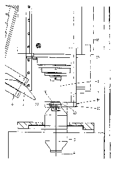
Figs. 1 and 2 show in schematic top plan viewa first
embodiment of a forming machine 1 for deforming metal cylinders,
which machine 1 comprises a rotatably drivable clamping device 2,
in which one end of a metal workpiece 3 is clamped down in a known
manner and by means of which said workpiece 3 can be rotated about
an axis of rotation 4. In this figure, the workpiece 3 is shown in
its original form of a circular cylinder (dotted lines), and in
the intended form (full line).
The workpiece 3 can be deformed by means of a forming
roller 5, which is rotatably mounted in a holder 6. To that end,
the forming roller 5 must follow a specific path of movement
comprising one or more deforming curves, the holder 6 being
attached to a slide group 7, which may be configured as
described in the aforesaid European application No. 0 125 720.
The slide group 7 comprises an upper slide 8, on which the
holder 6 is mounted, which upper slide is mounted on an upper bed
in such a manner as to be capable of reciprocating movement in a
first direction. Said upper bed is connected to a lower slide 9,
which is mounted on a lower bed in such a manner as to be capable
of reciprocating movement in a second direction perpendicular (in
this example) to said first direction. The upper slide 8 and the
lower slide 9 are each provided with driving means 10, 11, such as
a pneumatic or hydraulic cylinder, a servo motor or the like.
CA 02542912 2006-04-11
WO 2005/042180 PCT/NL2004/000776
Positioned opposite the workpiece 3 is a tailstock
12, which is known per se, which head is mounted on the same
machine bed 14 as the clamping device 2 and the slide group
7, capable of reciprocating movement on rails 13. The tail-
stock 12 is provided with a mandrel 15, whose (imaginary)
central axis coincides with the axis of rotation 4 of the
clamping device, which mandrel is provided with a annular
stop shoulder 16 positioned a few centimetres from the end of
said mandrel. Furthermore, a detector 19 is connected to the
tailstock 12 via a rod 17 and driving means 18, such as a
pneumatic or hydraulic cylinder, a servo motor or the like
(note: the detector 19 is the only part that is shown in side
elevation) . In this embodiment, the detector 19 comprises a
U-shaped element 20 at the end of the rod 17, the spacing be-
tween the legs thereof preferably being larger than the
external diameter of the workpiece 3 that is to be deformed.
A laser diode 22 and a laser sensor 23 may be connected to
respective ends of said legs. In the activated condition of
the laser 22, the laser beam will be positioned to the right
or to the left of the mandrel 15, in such a manner that said
beam is not interrupted by the mandrel 15. The detector 19
can be reciprocated by the driving means 18 in a direction
parallel to the axis of rotation 4 of the clamping device 2.
The rod 17 is furthermore connected to a known linear posi-
tion sensor 24, for example a linear encoder, which is
fixedly connected to the tailstock 12.
The clamping device 2, the driving means 10, 11,
18, the detector 19 and the linear position sensor 24 are
connected to a control unit 25 (schematically indicated) in a
known manner. Stored in said unit 25 are inter alia the de-
forming curves to be followed by the forming roller 5, the
feed rates and the rotational speed of the clamping device 2.
In this example, a cylindrical workpiece 3 is de-
formed into a housing, e.g. for a catalytic converter
substrate for use in an exhaust system for an internal com-
bustion engine. The deforming curves to be followed by the
forming roller 5, the feed rates and the rotational speed of
CA 02542912 2006-04-11
WO 2005/042180 PCT/NL2004/000776
6
the clamping device 2 have preferably been obtained during a
teach-in phase as described in the aforesaid EP 0 125 720, in
order that said parameters are precisely geared to a specific
workpiece and a specific product.
The method according to the invention can be car-
ried out as follows by means of the forming machine as
described herein and as shown in the figures:
The values as determined for a specific combination
of a workpiece 3 and a product (deforming curves, feed rates
and rotational speed, among other things) are loaded into the
control unit 25. The workpiece 3 is clamped down in the
clamping device 2. The detector 19 is moved in the direction
of the workpiece 3, until the laser beam is interrupted by
said workpiece 3. The detector is then moved back to a posi-
tion just before the interrupting position. The position of
the extreme edge of the workpiece 3 is thus determined, in
this case as a function of a coordinate on the axis of rota-
tion 4 of the clamping device 2, and input into the control
unit 25. Subsequently, the rotating workpiece 3 is deformed
according to a first deforming curve during a first pass.
During the deforming process, the detector 19 continues to
follow the extreme edge and communicate the position of said
edge to the control unit 25. The control unit 25 then deter-
mines whether the position of said edge corresponds to the
stored (expected) position or whether it is leading in ad-
vance of or lagging behind said position.
As long as the actual position falls within the
tolerance of the stored position, the programmed values are
not interfered with.
If the actual position is leading by too much, and
there is a risk of the deformed part of the workpiece becom-
ing too long, the feed rate is increased and/or the
rotational speed is decreased, or one or more of the deform-
ing curves is/are shifted inwardly, i.e. in the direction of
the axis of rotation 4, or their shape is changed without lo-
cally reduced portions being created. It stands to reason
that it is also possible to use combinations of said magni-
CA 02542912 2006-04-11
WO 2005/042180 PCT/NL2004/000776
7
tudes, and the control unit may be so arranged that the feed
rate is changed first, for example, and that one or more de-
forming curves is/are subsequently shifted inwardly if a
specific threshold value is exceeded.
If there is a risk of the deformed portion becoming
too short, the feed rate is decreased and/or the rotational
speed is increased, or one or more of the deforming curves
is/are shifted outwardly, i.e. in a direction away from the
axis of rotation 4.
In cases in which not only the diameter of the ex-
treme edge and the length of the deformed portion of the
finished product are specified, but also the changes in the
shape of the wall of the deformed portion, for example, the
feed rate, the rotational speed and the force exerted on the
workpiece by the forming roller (for parts present on a form-
ing tool) can be successively adapted, for example, whilst
leaving the deforming curves unchanged.
During the final pass, the end of the workpiece is
deformed on the mandrel and against the annular stop shoul-
der, so that the internal diameter and the length of the
obtained extreme edge of the semi-manufactured product are
precisely defined
Figs. 3-5 show variants of the detector 19. In Fig.
3, the forming machine is equipped with a detector that is
provided with a series of a laser diodes and a series of cor-
responding laser sensors positioned opposite thereto. In that
case the position of the extreme edge of the workpiece can be
determined on the basis of the number of laser beams that are
interrupted by said edge. This enables a simplification of
the control loop according to which the detector 19 scans the
extreme edge of the workpiece or, if the series is suffi-
ciently long, said control loop may even be left out
altogether (Fig. 4). In that case sufficient sensors will be
present for following the position of the extreme edge with-
out moving the detector.
Besides carrying out contactless measurements, it
is also possible to scan the extreme edge of the workpiece by
CA 02542912 2006-04-11
WO 2005/042180 PCT/NL2004/000776
8
means of a detector, one or more parts of which, e.g. a bear-
ing 26 which is urged into contact with said edge with a
suitable force by means of a spring 27 (Fig. 5).
Figs. 6 and 7 are schematic top plan views of a
second embodiment of the forming machine 1, in this case used
for deforming a metal, disc-shaped plate 3. The machine 1
largely corresponds to the machine that is shown in Fig. 1,
but in this case the machine comprises a spindle 28, which is
clamped down in the rotatably drivable clamping device and
which determines the shape of the inner wall of the final
product. The plate 3 is clamped against the spindle 28 by
means of a tailstock 12 in a known manner, and can be de-
formed into a desired product, such as a lamp a reflector,
and the expansion vessel or the like, by means of a forming
roller 5 in a number of passes (the result of a number of
said passes is illustrated in full lines).
A detector 19 is connected to the tailstock 12 via
a rod 17. In this embodiment, the detector 19 comprises two
series of laser diodes 22 and sensors 23 disposed opposite
each other. The laser beams extend parallel to the axis of
rotation 4, in such a manner that the spacing between said
beams and said axis 4 increases in radial direction. The sen-
sors 23 measure which laser beams are interrupted by the edge
of the workpiece 3. The position of the extreme edge of the
workpiece 3 can then be determined on the basis of the number
of laser beams that are interrupted by said edge.
It is also possible to use other detectors than the
lasers and sensors that have been described above, of course,
such as one or more fibre electrical sensors, cameras (e.g.
CCD or CMOS), or other optical measuring systems. Preferably,
said systems are adjustable, so that the detector can be
adapted to a specific workpiece and/or product.
It stands to reason that the invention is not lim-
ited to the embodiment as described above, which can be
varied in many ways within the scope of the invention as de-
fined in the claims. Thus, the invention can also be carried
out by using a static workpiece and a rotating tool, or a ro-
CA 02542912 2006-04-11
WO 2005/042180 PCT/NL2004/000776
9
tating workpiece and a rotating tool, as described in Inter-
national application WO 02/062500, for example. Furthermore
it is for example possible to use the invention for eccentri-
cally or obliquely deforming workpieces.