Note: Descriptions are shown in the official language in which they were submitted.
CA 02543354 2006-04-20
WO 2005/043740 PCT/GB2004/004512
Maanetia Gearing of Permanent Magnet Brushless Motors
This invention relates to the magnetic gearing of
permanent magnet brushless motors.
Permanent magnet brushless motors are known which are
capable of providing variable speed outputs. The motor
characteristics are linear, generating high torque at low
speeds and high speed at low torque levels.
In certain applications, the range of speed and torque
characteristics of a particular motor may not be sufficient to
cover the desired range, even though the output power of the
motor may be sufficient. In such circumstances two options are
available. Firstly, a more powerful motor could be used to
cover the entire range or secondly, mechanical gears could be
provided for the motor. Both of these methods add cost and
weight to the system.
Canadian Patent Application No. 2341095 discloses an
alternative to the above-mentioned methods which uses a
technique in which the speed and torque can be varied inside
the motor and the only additional item required is a switching
circuit. A prerequisite of this technique is that the stator
coils of the motor must be segmented into at least two or more
sections, which are evenly or perhaps unevenly distributed
throughout the stator slots. The switching circuit can then be
used to change the number of coil segments which are connected
to the supply. Such an arrangement utilises the control of the
induced back electromotive force (back emf) to control the
speed by selectively altering the number of conductors which
are connected to the supply. This in effect also alters the
torque with changing speed of the motor.
In the main embodiment of Canadian Patent Application
No. 2341095, each of the motor windings comprises a plurality
of series-connected sections provided by tappings in the
winding, which can be selectively connected across the supply.
With just one of the coil segments connected across the supply,
the motor will produce a high speed but a low torque. However,
CA 02543354 2006-04-20
WO 2005/043740 PCT/GB2004/004512
2
with a higher proportion of coils connected in series across
the supply, the motor will produce a lower speed at the same
torque . In this manner, the speed but not the torque of the
mot or can be varied by selectively connecting the windings in
series .
In an alternative embodiment, each of the motor
windings comprises a plurality of parallel-connected sections,
which sections can be selectively connected in parallel across
the supply. With just one of the coil segments connected across
the supply, the motor will produce a high speed but a low
torque as previously described. However, with a higher
proportion of coils connected in parallel across the supply,
the motor will produce high torque at the same speed. In this
manner, the torque but not the speed of the motor can be varied
by selectively connecting the windings in parallel.
A disadvantage of either arrangement is that sections
are redundant when running the motor during some configurations
and thus copper (I~R) losses will be higher because the
cross-sectional area of copper utilised decreases as the number
of active sections decreases. Also, the presence of redundant
sections means that the net resistance of the coils is not
opt imised in all configurations and hence the supply current
or voltage has to be controlled to avoid damaging the connected
coils. Since speed and torque are functions of the current, any
limitation of the current affects the performance of the motor.
In most situations, the supply current to the motor is
limited (for example in domestic mains to 13 amps), and thus
the attainable speed and torque will not be optimised when some
coi is are out of circuit.
We have now devised a permanent magnet brushless motor
which alleviates the above-mentioned problem.
In accordance with this invention, there is provided a
permanent magnet brushless motor comprising a winding divided
int o a plurality of sections and switch means for selectively
connecting the sections of the winding in one of a plurality
CA 02543354 2006-04-20
WO 2005/043740 PCT/GB2004/004512
3
of different configurations, wherein each section is connected
in series and/or parallel with all other sections of the
winding.
The switch means can then be used to change magnetic
gears, by changing the configuration of the coil segments in
series, parallel or a combination of both, which are connected
to the supply. Vale call such an arrangement magnetic gearing
because it utilises the control of the induced back
electromagnetic force (back emf) to control the speed by
selectively altering the winding configuration which are
connected to the supply. This alters the torque with changing
speed of the motor.
In contrast to known methods of varying the speed or
torque by coil manipulation, the present invention is
1 5 distinguished in that all of the winding segments contribute
towards the motor operation no matter which section
configuration is being employed. In this manner, all of the
available copper is utilised at all times, thereby keeping the
copper loss of the motor to a minimum.
The advantage of utilising all of the winding sections
is the reduction of the motor's copper loss. Normally the
stator slots are packed with as much copper wire as possible,
either by maximising the number of turns, or by maximising the
wire diameter (if the number of turns have been predetermined
2 5 for the design). In this manner the cross-section area of
copper is maximised for the slot, so that the resistance of the
coils is kept to a minimum. Hence the copper loss for the motor
will always be kept to a minimum.
In a first configuration, the switch means is
preferably arranged to connect all of the winding sections in
parallel. In this configuration at a given current I, the motor
is able to reach high speeds at relatively low torque levels.
In a second configuration, the switch means is
preferably arranged to connect all of the winding sections in
3 5 series. In this configuration at the same current I, the motor
CA 02543354 2006-04-20
WO 2005/043740 PCT/GB2004/004512
4
is only able to deliver high levels of torque at relatively low
speeds.
In a third configuration, the switch means is
preferably arranged to connect some of the winding sections in
parallel, with at least one other section being connected in
series with the parallel-connected sections. In this
configuration at the same current, the motor is able to reach
speeds between that of the first and second configurations and
deliver a torque between the first and second configurations.
In order to further vary the speed v torque
characteristic of the motor, the voltage applied to the winding
may be pulse-width modulated, for example using said switch
means .
The speed v torque characteristic of the motor may also
be varied by rapidly switching the winding sections between
different configurations to obtain a characteristic
intermediate that of the configurations between which the
windings are switched.
Preferably the switch means is able to vary the
configuration of the winding connections whilst the motor is
running, in accordance with predetermined operating parameters.
Preferably, the switch means is able to vary the
configuration of the winding connections whilst the motor is
running, in accordance with the output of means for sensing an
operating parameter of the motor such as the current, voltage,
speed or torque, or in accordance with the output of means for
sensing an operating parameter of the article being driven by
the motor such as velocity. In the case of a multi-phase motor
having a plurality of windings, the switch means may vary the
configuration of the winding connections of a conducting phase
whilst the motor is running, in accordance with the back emf
measured across the winding of non-conducting phase or a
section thereof .
Alternatively, the switch means is able to vary the
configuration of the winding connections in accordance with
CA 02543354 2006-04-20
WO 2005/043740 PCT/GB2004/004512
time or an operating cycle or program.
Alternatively, means may be provided for manually
changing the configuration of the winding connections.
Preferably all of the sections of the winding are wound
5 in parallel during assembly, with the current preferably
flowing through each section in the same direction.
One of the sections of the winding may comprise a
different number of turns from another section. Also, one of
the sections of the winding may comprise a conductor having a
different cross-sectional area than the conductor of another
section.
An embodiment of this invention will now be described
by way of an example only and with reference to the
accompanying drawings, in which:
Figure 1 is a schematic diagram of one phase of a 3-
phase permanent magnet brushless motor in accordance with the
present invention;
Figures 2 to 6 are schematic diagrams showing various
connections of sections of the motor of Figure 1;
Figure 7 is a table showing the switch states of the
motor of Figure 1 with reference to the connections of Figures
2 to 6~
Figure 8 is a graph of speed v torque for the
connections of Figures 2 to 6: and
Figure 9 is graph of speed v torque to illustrate how
the ideal motor characteristics for a washing machine can be
achieved using the motor of Figure 1.
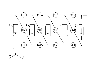
Referring to Figure 1 of the drawings, there is shown
a 3-phase permanent magnet brushless DC motor comprising three
star-connected phases R, Y, B 18 slots, 12 poles and a slot pitch
of 1. The stator outer diameter, inner diameter and length are
110mm, 55mm and 75mm, respectively. The air gap is 0.5mm, the
magnet width and thickness are l0mm and 4 mm, respectively.
Each phase comprises a winding having, for example, five
conductors or so-called sections 1-5 of 0. 63mm enamelled copper
CA 02543354 2006-04-20
WO 2005/043740 PCT/GB2004/004512
6
which are co-wound in parallel through the relevant stator
slots of the motor. The supply voltage to the motor is 180
volts DC.
The first end of the first section 1 of one phase R is
connected to the first ends of the first sections of the other
two phases Y, B. The first end of the first section of the
phase R is also connected to the first end of the second
section 2 of that phase R via a switch Sl. Likewise, the first
ends of the other sections 3,4,5 are connected to adjacent
sections via respective switches S2, S3, S4.
Similarly, the second end of the first section 1 of the
phase R is connected to the second end of the second section
2 of that phase R via a switch S9. Likewise, the second ends
of the other sections 3,4,5 are connected to adjacent sections
via respective switches 510, 511, 512. The second end of the
fifth section 5 is also connected to the supply.
The second end of the first section 1 of the phase R is
connected to the first end of the second section 2 of that
phase R via a switch S5. Likewise, the second ends of the other
sections 2,3,4 are connected to the first ends of adjacent
sections via respective switches S6, S7, S8.
Referring to Figures 2, 7 and 8 of the drawings, when
the motor is initially started, only the switches S5 to S8 are
energised such that the sections 1-5 are connected in series.
In this manner the supply current flows through each series-
connected section 1-5 in the same direction with respect to
each section's polar orientation (as indicated by the arrows
in Figure 1): it is imperative that this is always the case.
Had one of the sections (e.g. section 4) been oriented in the
opposite direction, the flux produced by section 4 would oppose
the flux produced by sections 1, 2, 3 and 5.
The torque of the motor is directly proportional to the
current and, as long as the starting torque is high enough to
overcome the load attached to the motor, the rotor begins to
turn. This is accompanied by the generation of a back emf in
CA 02543354 2006-04-20
WO 2005/043740 PCT/GB2004/004512
7
the coils, which begins to cancel out the supply voltage, so
that the current available for the phase coils begins to
reduce, as does the torque produced by the motor.
The back emf, is directly proportional to the number of
turns in the phase coils, the magnetic flux produced by the
permanent magnets, the number of permanent magnet pole pairs
and the angular speed of the rotor. Other factors, such as the
interconnection between the coils and the phases and the number
of phases also affects the back emf generated.
The consequence of this behaviour is that, the motor
will continue to accelerate until the torque produced by it,
equals the load. From this point on, the motor will continue
to rotate at a constant speed. If at any instance the load is
altered, the motor will automatically adjust its torque (and
consequently, its speed) in order to balance the load.
The maximum speed that can be attained by a motor,
occurs when there is no load attached to the motor. Ideally,
this occurs when the back emf generated in the phase coils is
equal to the supply voltage, at which instance there is no
current flowing through the coils to produce any torque; this
situation is referred to as the no load speed.
In reality, the back emf will always remain marginally
lower than the supply voltage (even at no load speed). This is
because a small portion of power supply is used up in
overcoming frictional forces due to windage and the bearings,
as well as iron losses of the motor.
It is evident from the graph of Figure 8 that the motor
is limited to performance criteria within the speed v torque
line for Figure 2. The graph indicates that the motor can
manage a maximum speed of 584 rpm and a maximum torque of 28.1
Nm. As a further example, it can also provide torque of 8 Nm
up to a maximum speed of approximately 400 rpm, or conversely,
the motor running at 400 rpm, can provide up to a maximum
torque of approximately 8 Nm.
If the desired motor performance falls beyond the 10
CA 02543354 2006-04-20
WO 2005/043740 PCT/GB2004/004512
8
amp line, for instance 14 Nm at 600 rpm, the motor parameters
need to be altered in order to cater for the additional power
requirements.
Referring to Figures 3, 7 and 8 of the drawings, the
motor's performance can be changed by altering the
configuration in which all of the motor's windings are
connected. By energising the switches in accordance with Figure
7, sections 1 and 2 can be connected in parallel and this
parallel set is then connected in series with section 3, 4 and
5 (which are connected in series with one another).
It is evident from the graph of Figure 8 that the motor
is now limited to performance criteria within the speed v
torque line for Figure 3. The graph indicates the motor will
now generate a no load speed of 725 rpm and a stall torque of
34.6 Nm.
Referring to Figures 4, 7 and 8 of the drawings, the
motor's performance can be changed again by energising the
switches in accordance with Figure 7, so that sections 1, 2 and
3 are connected in parallel and this parallel set is then
connected in series with sections 4 and 5 (which are connected
in series with one another).
It is evident from the graph of Figure 8 that the motor
is now limited to performance criteria within the speed v
torque line for Figure 4. The graph indicates the motor will
now generate a no load speed of 966 rpm and a stall torque of
46.1 Nm.
Referring to Figures 5, 7 and 8 of the drawings, the
motor's performance can be changed again by energising the
switches in accordance with Figure 7, so that sections 1, 2,
3 and 4 are connected in parallel and this parallel set is then
connected in series with section 5.
It is evident from the graph of Figure 8 that the motor
is now limited to performance criteria within the speed v
torque line for Figure 5. The graph indicates the motor will
now generate a no load speed of 1449 rpm and a stall torque of
CA 02543354 2006-04-20
WO 2005/043740 PCT/GB2004/004512
9
69.0 Nm.
Referring to Figures 6, 7 and 8 of the drawings, the
motor's performance can finally be changed by energising the
switches in accordance with Figure 7, so that sections 1, 2,
3, 4 and 5 are connected in parallel.
It is evident from the graph of Figure 8 that the motor
is now limited to performance within the speed v torque line
for Figure 6. The graph indicates the motor will now generate
a no load speed of 2898 rpm and a stall torque of 136.7 Nm.
At first sight, one may consider that the best option
would be to implement the configuration of Figure 6 (i.e. all
sections in parallel), since this choice yields the greatest
range in terms of both speed and torque. However, although the
voltage supplied to all of the configurations is the same (180
volts DC), the current varies from one configuration to the
next. In practical applications there will always be a current
limit, for example most household appliances are limited to 13
amps. Referring to Figure 8, if a notional 10 amp limit is
applied to each configuration, it will be seen that the maximum
torque achievable by the configuration of Figures 2 to 6 are
29.7, 23.7, 17.8, 11.9 and 5.9 Nm respectively. Thus, by
operating the switches to change between the various
configurations, whilst keeping the motor within the confines
of the 10 amp limit, a performance can be achieved as shown in
the shaded area of the graph. Accordingly, it will be
appreciated that a gearing system for the motor can be provided
by operating the switches, thereby allowing the motor to
generate higher torque (at low speed) and higher speed (with
low torque) than would be possible with any single
configuration (with limited current supply). Thus, when the
motor is initially energised, all sections can be connected in
series as shown in Figure 2, such that a high starting torque
is achieved well within the confines of the 10 amp limit.
The switches Sl to S12 can be relays or semiconductor
devices. In the case of semiconductor devices, a plurality of
CA 02543354 2006-04-20
WO 2005/043740 PCT/GB2004/004512
devices could be included in a single package. Individual
switches for example S1, S5 and S9 can be configured into a
single mechanical or electronic switch. In this case when 1 and
9 are ON, then 5 is OFF. When 5 is ON, then 1 and 9 are OFF.
5 This way only 4 switches will be required per phase instead of
12 switches.
Referring to Figure 9 of the drawings, there is shown
a graph of the required speed v torque curve 20 for a domestic
washing machine superimposed onto the graph of Figure 8. At
10 present the required speed and torque are normally achieved by
using induction motors running at high speeds with appropriate
mechanical gearing and drive belts, or by using a large DC
direct drive motor. However, it. can be seen that the required
range of speed and torque can easily be achieved within the
current confines using a reasonably sized direct drive
brushless DC motor in accordance with this invention.
It will be seen that the configurations of Figures 3
and 4 are not necessary to provide the required speed v torque
curve for a domestic washing machine and thus some cost savings
can be achieved by omitting some of the switches.
It should be noted that the mufti-segmented coils
within a single phase need not be wound using the same wire
diameter or the same number of turns, however, all the phases
must be wound in an identical manner. For instance, section 1
of every phase must be wound with the same wire and have the
same number of turns. Coil section 2 can have a different
number of turns and it can be wound using a different wire
diameter to that of section 1, but coil segment 2 of every
phase must be identical and the same applies to all other
segments.
It will be appreciated that whilst the embodiment
hereinbefore described utilises 3-phases, the invention applies
to a motor having any number of phases. Furthermore, the
invention also applies to permanent magnet brushless
synchronous motors, which have similar speed torque
CA 02543354 2006-04-20
WO 2005/043740 PCT/GB2004/004512
11
characteristics.
The configurations discussed in Figures 2 to Figures 6
are not the only possible combinations. For example, another
possible combination is coil sections 1 and 2 connected in
parallel and coil sections 3 and 4 connected in parallel, the
two parallel sets being connected in series with one another
and with the remaining section 5. This configuration will
produce the same motor characteristics as the arrangement shown
in Figure 4.
Yet another configuration can be obtained by connecting
sections 1, 2 and 3 in parallel and sections 4 and 5 in
parallel and then connecting the parallel sets in series with
one another. This will yield motor characteristics that are the
same as the one produced by the configuration shown in Figure
5.
The number of speed-torque characteristics that can be
obtained is dependent on the number of winding sections
provided (per phase), which is limited to some finite number.
The motor operates at its most efficient level when it is
running as close as possible to its no load speed. For this
reason, it is undesirable to allow the motor to compensate for
an increase in load, by automatically reducing its speed (on
the speed-torque characteristics line). It would be far better
to meet the demands of the increase in load through magnetic
gearing, so that the new torque level is achieved whilst the
motor continues to run close to its no load speed. However, in
order to meet all possible torque levels (within the given
range of the motor) the motor would require an infinite number
of magnetic gears and therefore, an infinite number of winding
sections and switches.
In an alternative embodiment, it is possible to achieve
any speed torque curve in between those obtained by altering
the configuration of the windings by interchanging between the
two configurations very rapidly, so that the motor is not
operating at the characteristics of either configuration, but
CA 02543354 2006-04-20
WO 2005/043740 PCT/GB2004/004512
12
somewhere in between. The rapid switching between the two
configurations can be achieved by feeding a pulse width
modulated (PWM) signal to the switches (S1 to S12) and the duty
cycle of the PWM is altered to achieve the desired intermediate
speed and torque.
For example, consider a first configuration with all
winding sections connected in parallel; this gear provides the
highest speed the motor can achieve and therefore, it is the
highest gear. The next gear down from this, is achieved by
connecting one of the winding sections in series with the
remaining parallel sections; this provides the next highest
speed.
If the PWM has a duty cycle of 1000, the gear will
change from the highest to the next lower gear and remain
there. Conversely, if a duty cycle of Oo (i.e. no signal) is
chosen, the motor will remain in the highest gear. Choosing a
duty cycle between 0 and 1000 will yield a gear and
consequently, a motor speed and torque between the highest two
gears; i.e. an intermediate gear.
If desired, the gearing can be switched directly
between the highest gear (all sections in parallel) and the
lowest gear (all sections in series) . The duty cycle of the PWM
can then be used to select a speed/torque characteristics
anywhere in between the two extremes of the motor performance.
However, the resolution and consequently, the accuracy with
which a desired speed can be achieved decreases as the full
range of the gearing scale increases. This, to some extent can
be compensated by increase in PWM frequency.