Note: Descriptions are shown in the official language in which they were submitted.
CA 02543695 2006-04-20
PROCESS AND APPARATUS FOR SEPARATING
OIL AND OIL BASED PRODUCTS FROM AQUEOUS FLUIDS
SPECIFICATION:
FIELD OF THE INVENTION
This invention relates to a process and equipment for separating oil and oil
based derivative products
from an aqueous fluid, including free floating oil, oil-in-water emulsions,
water-in-oil emulsions and
chemical emulsions created by surfactants. Oil and oil based derivative
products are defined herein as
any products which are attracted to an oleophilic surface.
BACKGROUND AND PRIOR ART
Oil and oil based derivative products are found throughout industry ranging
from vegetable and
hydrocarbon based oils to many liquid products derived from them. When these
products come in
contact with aqueous fluids, a variety of oil containing mixtures can be
created including free floating
oil, oil-in-water emulsions and water-in-oil emulsions. Emulsified oils can be
formed either
mechanically or chemically, with the former being caused by agitation of the
solution which breaks the
oil up into small particles, and the latter being caused by a surfactant
coming in contact with the oil
particles and bonding with them.
Oily water and watery oil both pose significant treatment challenges for
industry and the environment.
Strict regulations have been developed in many jurisdictions to limit the
concentration of oil allowed
to be discharged to the environment in aqueous fluid streams. Similarly, the
amount of water allowed
to be present in various types of oil is also regulated, particularly where
excess water could adversely
affect the performance of equipment using the oil.
Many treatment processes and types of equipment have been developed in the
past to separate such
fluids. However, each has significant limitations which has led industry to
continue searching for better
solutions.
-1-
CA 02543695 2006-04-20
Existing separation systems generally target specific properties of the fluids
to achieve improved phase
separation, including (1) their density differences, in which gravity is used
to promote the flotation of
one product and sinking of the other; (2) their density differences, in which
centrifugal force is used to
separate lower density fluids from higher density fluids; (3) their surface
attraction properties, in which
adsorption or absorption processes are used to attract target fluids to a
prepared media surface which has
an increased affinity for one fluid relative to the other fluid; (4) their
chemical and physical properties,
in which processes have been developed such as dissolved air flotation, pH
adjustment, temperature
adjustment or addition of chemicals to increase the tendency of the target
fluid to differentiate itself from
the carrier fluid; (5) their coalescing properties, in which some processes
use specially designed
coalescing plates or media to encourage one fluid to attach and coalesce on
the media; (6) their particle
size differences, in which some processes use filter systems to capture one
fluid while letting the other
pass through.
All of these technologies have significant disadvantages and limitations which
give rise to the need for
the present invention, as follows:
The most widely used separation process, gravity separation, utilizes density
differences between two
fluids to encourage one to float and the other to sink. Stoke's Law governs
how this process occurs, with
the settling or rising velocity of a particle being directly related to its
diameter and its density relative
to the other fluid. Gravity separation can be achieved using any container
which provides a residence
time and a non-turbulent setting to permit the denserproduct time to sink and
the less dense product time
to float. This process works most effectively with larger oil particles, as
they differentiate themselves
more quickly from the other fluid and rise quickly to the surface. As the size
of oil particles in the fluid
decrease, they take longer to float, and hence require a larger container to
provide the necessary
residence time. When the oil particles become too small to float within a
reasonable time frame, or
when chemical emulsions are present in the solution, this process is no longer
commercially feasible.
Gravity separation as a process is generally limited to removing oil particles
150 microns or larger in
size, and is ineffective for removing chemical emulsions.
A second type of density separation process utilizes centrifuges or 'hydro-
cyclones' to induce a
centrifugal force on the fluid, which causes the higher density products to
migrate to the outside of the
-2-
CA 02543695 2006-04-20
separator, and lower density fluids to migrate towards the center. This
process is capable of removing
oil particles down to approximately 5-10 microns in size, but usually involves
significant capital costs,
energy costs, maintenance and space requirements. It cannot effectively remove
particles smaller than
- 10 microns in size.
Adsorption and absorption based processes, such as those which use activated
carbon or prepared clay
as a media, achieve separation of oil from the aqueous fluids by permanently
affixing the oil particles
to the media's own surface as they pass through. When the media surfaces
become saturated with oil,
the media must be disposed of as a waste product itself, creating other waste
management issues, and
a need for continual replacement of media. These systems also do not recover
the target fluid for re-use
or re-cycling, and are very sensitive to fluid containing viscous materials or
particulate matter, as they
act as filters in the presence of such materials and can quickly plug up.
Chemical and physical property adjustment processes generally require the
addition of chemicals, a
relatively long residence time in a large treatment chamber, high capital
costs and high operating and
maintenance costs. They also generally require the storage and use of various
chemicals which create
environmental management issues.
Existing processes using coalescing systems generally rely on physical or
chemical attraction of the oil
molecules to a prepared substrate which encourages the oil molecules to
coalesce into larger particles.
When the particles grow large enough, they release from the substrate and
float to the surface as free oil.
Prior art in this area has generally been limited in the size of oil particles
they can remove, require
significant maintenance effort, and are ineffective for separating chemical
emulsions.
Processes using filtration systems generally utilize filters or membranes
which are designed to strain out
larger molecules such as oil, while letting smaller molecules such as water
pass through. Removing
very small oil particles in this manner, however, requires the use of very
small pore spaces in the filter
to be effective. As such, these processes are extremely sensitive to the
presence of particulate matter and
high viscosity fluids in the fluid stream, which can quickly block their pore
spaces and result in a
requirement for continuous cleaning and maintenance.
-3-
CA 02543695 2006-04-20
Prior patents of background relevance to the current invention are listed
below:
US Pat. #4139 463, US Pat. #4088 578, US Pat. #4011 158, and US Pat. #3558 482
- These describe
gravity separation processes.
WO Pat. #2004/087286 Al, US Pat. #6902 678, US Pat. #5227 071, US Pat. #4802
978, US Pat. #4426
293, and US Pat. #3951 814 - These describe types of apparatus which use
coalescing media to separate
emulsified oils.
US Pat. #6475 393 and US Pat. #6180 010 - These describe a method of infusing
media substrate
materials to give such materials a greater affinity for attracting oil
molecules;
WO Pat. #2004/087296 A1 - This patent describes an apparatus for using
pressurized vessels and natural
coalescing media to encourage separation of oil emulsions down to 0.5 microns
in size.
METHOD BY WHICH THE PRESENT INVENTION OVERCOMES PRIORART PROBLEMS
It is an object of this invention to provide an oil recovery system which
allows all phases of an oily liquid
to be separated in one simple process including free floating oil,
mechanically emulsified oil, chemically
emulsified oil, and oil particles less than 0.5 microns in size, without
requiring filters, membranes,
chemicals, aeration, pH adjustment, property adjustment of fluids, outside
energy requirements or
moving parts. It is also an object of this invention to separate the fluids in
solution so they can each be
recovered as a separate fluid for re-use or re-cycling.
To achieve this, a primary separation chamber is used as a first stage in the
process to separate any high
viscosity and readily flotable products, using a standard gravity separation
process. Removal of such
products at this stage prevents them from impairing the function of the
downstream conditioning
element.
In a second stage of the process, the solution from the primary chamber passes
through a conditioning
unit which uses a highly oleophilic substrate element with small pore spaces
(1-100 m) to force small
emulsified oil particles to pass close to the substrate surface as they pass
through, encouraging them to
-4-
CA 02543695 2006-04-20
attach to the substrate material and coalesce into larger particles. When
these particles grow large
enough on the substrate material, they release from it as larger particles and
re-enter the fluid discharge
stream. This conditions the particles to be more easily removed by the final
separation stage
downstream. The conditioning element comprises a critical feature of this
invention by permitting the
following improvements to the prior art:
(1) The highly oleophilic nature of the conditioning element substrate speeds
up the coalescing
process significantly compared to current technologies, permitting the use of
much smaller
equipment;
(2) The highly oleophilic nature of the conditioning element substrate permits
chemically emulsified
oil particles to be de-emulsified and returned to their free floating or
mechanically emulsified
form in a simple and passive manner, which overcomes a major obstacle with the
prior art in
terms of both simplicity and ability to deal with chemical emulsions.
(3) Use of a conditioning element in this manner greatly increases the oil
removal efficiency of the
downstream coalescing stage, permitting a much smaller overall system size and
allowing a
much coarser coalescing media to be used in the final downstream stage
compared to competing
technologies.
(4) The conditioning element provides a function of protecting the downstream
separation media
from fouling due to the presence of particulate matter. Because the
conditioning unit pore spaces
are smaller than any downstream media in the system (1-100 m), any clogging
will intentionally
occur at the conditioning element, where corrective action requires only
unscrewing the housing
and dropping in another disposable conditioning element, as opposed to prior
art systems which
require the entire separator to be dismantled and cleaned in such instances.
(5) The conditioning unit fulfills a function of providing a fast and simple
means of field adjusting
the oil removal efficiency of the system to accommodate different raw inlet
fluid qualities by
simply replacing the existing conditioning element with one of a different
pore size. Smaller
pore spaces in the conditioning element provide improved coalescing of small
oil particles, but
-5-
CA 02543695 2006-04-20
also creates higher pressure losses across the element, and resulting
sensitivity to fouling by
particulate matter. Conversely, larger pore spaces are less effective at
coalescing small oil
particles, but cause less pressure loss and less sensitivity to clogging from
particulate matter. The
easily interchangeable conditioning element provides a simple method of
adjusting oil removal
needs to a specific application without requiring a different system design or
equipment
alteration.
The third stage of the invention uses a coarsely graded, highly oleophilic
coalescing media (1- 9.5 mm)
in combination with gravity separation, to provide a simple and passive means
of quickly separating the
coalescing oil from the fluid. This improves upon the following problems
experienced by prior art:
(1) It allows the final oil removal stage to be accomplished with coarsely
graded media or substrate
materials, resulting in significantly reduced pressure losses through the
system, reduced
sensitivity to blockage from particulate matter, reduced maintenance and an
ability to process
higher water flows than competing technologies.
(2) It allows both fluids in the solution to be recovered as independent
liquid streams for re-use or
recycling, rather than bonding them permanently to a substrate which has to be
disposed of itself
(3) It allows continual system operation, without a need for replacing
substrate media when it
becomes saturated, eliminating the need for frequent replacement of media
materials common
to many other prior art inventions.
The system as a whole provides a much smaller, more lightweight and more
efficient separation system
than the prior art, and achieves such separation without a need for moving
parts, chemicals, adjustment
of liquid properties or external energy inputs, making it particularly suited
for use in remote locations
where energy supplies are limited, for areas where maintenance and operation
issues are a concern, and
for potentially explosive environments where the presence of electrical
ignition sources is not permitted.
In tests which demonstrate the effectiveness of the invention for use with
mechanically and chemically
emulsified oils, the following results are provided:
-6-
CA 02543695 2006-04-20
Test # 1: Oil removal efficiency in the presence of mechanical and chemical
oil emulsions
Date of Test: January 16', 2006.
Conditioning Element Type: String wound polypropylene cartridge filter (75 m)
treated with
oleophilic coalescing composition as manufactured by Aquatek
Environmental Inc.
Conditioning Element Size: 500 mm high x 100 mm dia. x 25.4 mm dia. hollow
core.
Flow Rate: 19 L/min.
Aqueous Fluid: Fresh water.
Inlet Fluid Mixture: Diesel oil and water, mechanically and chemically
emulsified,
with oil content ranging from 130 ppm to 728 ppm.
Oil Density: 850 g/ml.
Concentration of Surfactant: 3.1 ppm.
Oil content Measuring Device: Electronic oil content monitor, (Rivertrace
Engineering, certified
to MEPC.107 (49).
Test Fluid Preparation: Water, oil and surfactant were mixed continuously in a
large tank
with a 3,500 rpm centrifugal pump, ensuring that no free oil was
visible on the surface of the water during the test.
Test Set-up: A centrifugal submersible pump was placed in the raw fluid
mixing tank and connected to a discharge hose. A vertical filter
housing was installed downstream of the pump to house the
conditioning element. A conditioning element treated with
Aquatek's coalescing composition was placed in the housing. A
vertical separation tank was installed downstream of the
conditioning unit measuring 250 mm diameter by 760 mm high.
A partial height partition was installed inside this tank to divide
it into two equal compartments, extending from the bottom of the
tank to an height of 500 mm. The tank was filled to the top of the
partition on each side with treated granular perlite media (1 - 4.75
mm), leaving a space of 50 mm at the bottom to accommodate
water entry. Water entered the tank at the bottom, traveled up
-7-
CA 02543695 2006-04-20
over the partition and down the other side to exit the tank. An oil
content monitor was attached to the discharge from the system to
determine water quality discharging from the system.
Primary Separation Stage: No primary separation chamber was used in this test
as there were
no high viscosity or free floating oil products in the raw inlet
fluid.
Test Procedure: .1 Pump a 0.3% solution of mechanically emulsified diesel
oil through the system for 2 hours to pre-saturate the
conditioning unit and coalescing media with oil.
2. Pump the chemically emulsified test fluid through the
conditioning unit and separator and record oil
concentrations contained in the water immediately
upstream and downstream of the secondary separation
chamber.
In the test, oil removal efficiency of the system was defined as the amount of
oil removed by the
secondary separation chamber as a percentage of the emulsified oil which
entered the chamber. Oil
concentrations entering the separator were measured immediately before they
entered the secondary
separation chamber to ensure that removal rates reflected only the removal
rate for emulsified oils. If
oil concentrations from the raw inlet mixing tank were used in the
calculation, removal rates would have
been higher due to the fact that it would have included some free oil as well.
-8-
CA 02543695 2006-04-20
Test Results:
Time Oil Concentration Oil Concentration Reduction
(min.) before Separator (ppm) after Separator (ppm) (%)
0 2 0 n/a
6 1.0 2.5 98.1
182 3.1 98.3
14 728 4.1 99.4
18 624 5.2 99.2
468 5.4 98.8
22 312 5.6 98.2
27 312 3.8 98.8
312 4.6 98.5
34 312 4.5 98.6
38 286 6.8 97.6
39 312 7.9 97.5
41 593 15.0 97.5
47 416 14.0 96.6
55 493 17.0 96.6
61 11.0
Average: 98.6*
* In tests where no surfactant was added, removal rates increased to more than
99.0%.
The separated oil recovered from the top of the secondary separation chamber
in subsequent tests
revealed a water content in the recovered oil of less than 0.5%, allowing the
system to be used for
removing water from oil as well as oil from water.
-9-
CA 02543695 2006-04-20
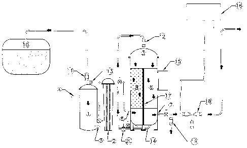
LIST OF FIGURES AND DESCRIPTION OF THE INVENTION
In drawings which illustrate embodiments of the invention, Figure 1 is a cross-
sectional view of the
invention as it would apply to one preferred embodiment.
The invention as illustrated consists of a primary separation stage (1), a
conditioning stage (2), and a
secondary separation stage (3). Raw inlet fluid enters the primary separation
stage through a pipe (4)
or another means of conveyance. In the primary separation stage (1) free
floating and high viscosity oils
of lower density than the aqueous fluid float to the top of the chamber. The
remaining aqueous fluid
containing emulsified oils exits at the bottom of the chamber (5) and travels
through the conditioning
stage (2). In this stage the fluid passes through a conditioning element where
oil particles attach to the
surfaces of the element and coalesce into larger particles. These particles
continue to grow until the
momentum of fluid passing through the element, combined with their increasing
buoyancy, causes them
to release from the conditioning element substrate and re-enter the discharge
flow as larger particles.
This flow then enters a secondary separation stage (3) through a pipe or other
means of conveyance (6)
and flows up through a volume of granular coalescing media (8). Oil attaches
to the surfaces of this
media and again coalesces into larger particles. When the oil on the media
reaches a certain volume, the
momentum of the uprising fluid flow, combined with the increasing buoyancy of
the oil, causes it to
release from the media and float to the surface as free oil. The remaining
aqueous fluid travels over the
divider wall (17) and back down through more coalescing media (9) before
exiting the system (7).
Coalescing media located on the discharge side (9) ofthe secondary separator
(3) captures anyremaining
oil emulsions. This media (9) is usually a smaller gradation than the inlet
media (8). When fluid flow
through the system stops, or a manual or pre-programmed backflushing cycle is
initiated, oil coalesced
on this media (9) releases and floats to the top of the secondary separation
chamber (3) as well.
In the invention, the primary separation stage consists of a gravity
separation chamber (1) in which oil
particles separate by gravity in accordance with Stoke's Law, with lower
density fluids rising and higher
density fluids sinking. The amount of fluid separation achieved during this
stage can be calculated from
the size of the oil particles in solution, the size of the primary chamber,
and the relative densities of the
fluids being separated, using Stokes' Law. Increasing the volume of this
chamber, without changing the
flow rate, will provide a longer residence time for the process to occur, and
consequently allow smaller
-10-
CA 02543695 2006-04-20
oil molecules to separate out. The shape of the chamber can also affect
removal rates by reducing fluid
velocity in the chamber. Reduced fluid velocities allow smaller molecules to
rise to the surface because
the momentum of flow traveling in the opposing direction is reduced.
Consequently, this chamber can be sized in accordance with Stoke's Law to
achieve any desired level
of separation of flotable products in solution based on the type of fluids
involved. It is a feature of this
invention, however, that the primary separation stage (1) does not need to be
sized large enough to
remove small molecules, or even free floating oil in general, as these will be
removed in subsequent
separation stages in any case. Rather, this stage needs only to be sized large
enough to remove a
majority of liquids in the inlet stream which have a kinematic viscosity
greater than 300 centistokes at
40 C. The purpose of this is to prevent high viscosity oils from traveling
through to the conditioning
element and blocking its pore spaces. The fact that other free floating oils
will naturally separate here
as well makes the primary separation stage (1) a convenient location for
removing the bulk of any free
oil in the inlet fluid. When the denser fluid is the largest portion of the
incoming solution, it is preferred
that the inlet port (4) be located near the top of the chamber, and the outlet
port (5) be located near the
bottom of the chamber, as shown on Figure 1. If the denser fluid is the
smallest portion of the incoming
solution, the entry (4) to the primary separation chamber (1) would
preferentially be located near the
bottom of the chamber, and the exit port located near the top.
In another embodiment of the invention, the primary separation stage (1) can
consist of either a
pressurized or non-pressurized container sized only large enough to separate
incoming fluids with a
kinematic viscosity greater than 300 centistokes at40 C.
In another embodiment of the invention the primary separation stage (1) can be
an open tank or any
similar container which provides a suitable residence time for the high
viscosity fluids to separate before
reaching the conditioning stage (2).
In another embodiment of the invention the primary separation stage (1), the
conditioning stage (2) and
the secondary separation stage (3) can be housed in either separate containers
or with one or all located
in the same vessel, to simplify construction and reduce equipment size and
weight, by partitioning the
vessel into compartments where each compartment will function as a separate
stage.
-11-
CA 02543695 2006-04-20
In another embodiment of the invention, the primary separation stage (1) can
be fitted with either manual
or automatically activated valves (11) to permit manual and/or automatic
discharge of separated liquids
from the top or bottom of the chamber to a holding container (10) or other
location.
In another embodiment of the invention, the primary separation stage (1) can
be fitted with an electronic
oil sensor (13) to permit the detection and automatic discharge of oil from
the chamber when the oil
collects to a pre-determined depth.
In another embodiment of the invention, the primary separation stage (1) can
be fitted with an overflow
feature whereby the collected fluids discharge automatically from the chamber
without a need for
valves, moving parts, exterior energy input or human intervention. This is
accomplished by having an
overflow weir or pipe placed in the top of the chamber to allow oil to
automatically overflow to a
selected discharge location when the oil reaches a sufficient height in the
chamber. As oil collects in
the chamber its surface elevation will automatically rise due to a greater
buoyancy relative to the
underlying aqueous fluid. When its surface elevation reaches the height of the
overflow weir, it will start
discharging automatically.
In another embodiment of the invention, the inlet and outlet ports (4) and (5)
for the primary separation
chamber (1) can have the inlet located near the bottom of the chamber and the
outlet located near the top
to accommodate applications where the incoming oil products are denser than
the aqueous fluid.
In another embodiment of the invention, the discharge location (11) for
removing separated fluids from
the primary separation chamber (1) can be located at either the top or bottom
of the chamber, depending
on whether the separated products to be drained off from this chamber are
denser than the aqueous fluid
or not.
In another embodiment of the invention, the primary separation stage (1) can
be eliminated from the
system entirely in situations where the inlet fluid contains no high viscosity
fluids which could cause
premature blockage of the conditioning element (2).
-12-
CA 02543695 2006-04-20
In another embodiment of the invention, the primary separation stage (1) can
be constructed of any
material that is physically suitable for holding oil and aqueous fluids for
the particular application
involved.
After the aqueous fluid leaves the primary separation stage (1), it enters a
conditioning unit (2) consisting
of a small micron highly oleophilic coalescing element, which is field
changeable. This element allows
all fluids and particulate matter measuring less than the pore size of the
element to pass through. As the
fluids pass through, oil particles contained in the fluid are forced close to
the surfaces of the coalescing
element, where the oleophilic properties of the element cause the oil
particles to attach to its surface.
After the conditioning element (2) becomes saturated with oil, the coalesced
oil droplets release from
the element as larger particles and re-enter the downstream flow.
The primary purpose of the conditioning element (2) is to increase the size of
oil particles passing
through the unit. In a preferred application, the conditioning element (2)
would be used in applications
where the incoming fluid contains no particulate matter large enough to get
trapped in the conditioning
element (2) matrix. However, it is a feature of the invention that if
particulate matter does occur in the
incoming fluid, the conditioning unit (2) will trap such material at the
conditioning unit stage (2) where
it can easily be removed, preventing it from clogging the downstream media of
the secondary separation
stage (3), where maintenance would be more difficult and time consuming.
It is a further function of the conditioning element (2) to provide an easy
and simple means of field
adjusting the separator to match the quality of the incoming fluid. The
conditioning element (2) can use
different physical sizes and pore space sizes for different applications,
depending on the flow
requirement through the unit, the allowable pressure loss across it, the
amount of particulate matter in
the fluid stream, and the maximum oil discharge concentrations allowed from
the system. Using smaller
pore spaces in the conditioning element (2) will provide improved oil
coalescing and removal
capabilities for smaller emulsions but will also cause higher pressure losses
across the element and make
it more sensitive to the presence ofparticulate matter. Consequently, a one
micron conditioning element
(2) will provide maximum oil separation efficiency, but pressure losses will
increase due to fluid friction
and turbulence through the pore spaces, and it will be more sensitive to
clogging with particulate matter
or highly viscous fluids. Consequently, all three variables need to be
considered when selecting the best
-13-
CA 02543695 2006-04-20
conditioning element (2) for a particular application. Pressure losses across
a conditioning element (2)
due to fluid flow are directly related to the fluid velocity going through it.
While increased pressure
losses will not affect the oil removal process of the system, it is good
design practice to limit such losses
across a new element to 7 Kpa or less. This can be accomplished by using a
conditioning element (2)
with either larger pore spaces, or by reducing fluid velocity through the
element through increasing its
size. Fluid velocity through a conditioning element (2) is affected by the
external surface area of the
element through which the fluid must flow, the size and quantity of pore
spaces, and the thickness of the
element. As such, fluid velocity through the element can be controlled by
either changing its height,
changing its exterior surface dimensions, changing its pore sizes or changing
its thickness.
It is a feature of this invention that a maximum fluid velocity exists through
the conditioning element
(2), above which the oil removal efficiency of the system will begin to
decrease. If the velocity is too
high, it can cause 'channeling' to occur through the conditioning element (2),
or cause pressure losses
to exceed levels acceptable to the Owner. 'Channeling' allows fluid to pass
through the conditioning
element (2) without being properly treated, leading to smaller oil particles
escaping downstream, and
lowering the overall oil separation rate. Consequently, when fluid flows
exceed this maximum velocity,
the size of conditioning element (2) needs to be increased, or one used with
larger pore spaces, to
accommodate the flow. The optimum size of conditioning element (2) to use is
one which results in the
fluid velocity being reasonably close to its maximum allowable, but leaving
some room for collection
of particulate matter. For a typical 500 mm long x 100 mm diameter x 75 micron
pore size string
wound polypropylene conditioning element (2) treated with Aquatek
Environmental Inc's oleophilic
coalescing composition, it has been found that the maximum flow rate is
approximately 19 L/min. This
will vary with different types of substrate materials and different inlet
fluids, however, and will need to
be identified for applications through field testing.
In a preferred embodiment of the invention, the conditioning element (2) will
consist of a fine (1-100
micron) string wound polypropylene filter cartridge treated with an oleophilic
coalescing composition
as manufactured by Aquatek Environmental Inc., which greatly increases the
element's affinity for
attracting oil molecules.
-14-
CA 02543695 2006-04-20
In another embodiment of this invention, the conditioning element (2) can be
treated or infused with
other oleophilic coalescing compositions which increase the oil attracting
capabilities of the substrate
material, such as compositions manufactured by MYCELX Technologies
Corporation.
In another embodiment of the invention, the conditioning element (2) can
consist of any substrate
material which can be manufactured to provide consistent pore spaces in the 1
to 100 micron size range,
and can attract oil and oil based products. Examples of some substrate
materials preferred for this
application include spun wound polypropylene, melt blown polypropylene,
granular perlite and
polyurethane.
In another embodiment of this invention, the conditioning element (2) may be
enclosed in either a
pressurized or non-pressurized container.
In a preferred embodiment of the invention, the conditioning element (2) will
be installed inside a
standard screw on filter housing which is simple and fast to remove and
service.
In another embodiment of the invention, the conditioning element (2) may be
installed in a non-
pressurized open container. For example, the conditioning element (2) can be
designed as a rectangular
sandwich shape unit which is installed in an American Petroleum Institute
(API) type gravity separator
to coalesce oil emulsions passing through the unit, without deviating from the
intent of the invention.
In another embodiment of the invention, the conditioning element (2) may be
located in the same
container as the primary separation chamber (1) and/or the secondary
separation chamber (3), to
minimize piping requirements, footprint size, equipment weight and cost.
In another embodiment of the invention, the conditioning element (2) can be
practically any shape or size
as long as the essential elements are provided, of having a controllable 1-100
micron element pore size,
an highly oleophilic media surface, a fluid velocity which doesn't cause
channeling and an element
which doesn't create excessive pressure losses.
-15-
CA 02543695 2006-04-20
In another embodiment of the invention, the conditioning stage (2) can utilize
more than one
conditioning element in series to achieve increased coalescing capabilities.
The secondary separation chamber (3) consists of a container divided into two
compartments by a
intermediate barrier (17) with oil coalescing media located on each side of
this barrier (8) and (9). A
space is provided at the top and bottom of the coalescing media for sludge
collection, fluid entry, fluid
exit and accumulation of separated fluids. Aqueous fluid travels from the
conditioning element (2) to
the secondary separation chamber (3) through a pipe or other means of
conveyance (6), flows in one
direction through the first volume of coalescing media (8), flows over the
barrier separating the two
compartments (17), and then flows in an opposing direction through a second
volume of coalescing
media (9) before exiting the chamber (7). If oil particles contained in the
inlet flow are less dense than
the aqueous fluid, it is a preferred embodiment of this invention that the
inlet port (6) be located near
the bottom of the chamber so that the fluid has to flow up through the first
volume of coalescing media
(8). This allows upward momentum of the fluid to assist in removal of oil
particles from the surface of
the media when it reaches a sufficient thickness. The exit port (7) in such
circumstances would
preferably be located near the bottom of the second volume of coalescing media
(9).
As oil molecules collect on the first volume of coalescing media (8), their
buoyancy, plus the upward
momentum of the incoming fluid flow, eventually causes them to release from
the media and float to
the top of the chamber as free product. The remaining aqueous fluid travels
down the other side of the
barrier (17) through more coalescing media (9), which captures any oil
remaining in the discharge fluid.
In a preferred embodiment of this invention, the first volume of coalescing
media (8) will consist of a
well graded coarse granular perlite material with a size range of 1- 9.5 mm,
treated with an highly
oleophilic coalescing composition as manufactured by Aquatek Environmental
Inc.
In another preferred embodiment of the invention, the second volume of
coalescing media (9) will
consist of a well graded granular perlite material with a size range of 1-
4.75 mm, treated with an highly
oleophilic coalescing composition as manufactured by Aquatek Environmental
Inc.
-16-
CA 02543695 2006-04-20
In a preferred embodiment of the invention, where limited particulate matter
exists in the inlet fluid and
pressure losses through the coalescing media is not a concern, the maximum
size gradation for both the
first coalescing media (8) and the second coalescing media (9) would be 4.75
mm, and more preferably
2.0 mm.
In another preferred embodiment of the invention, the granular coalescing
media (8) and (9) will provide
a large surface area to volume ratio to give oil particles a larger surface
area on which to attach.
In another preferred embodiment of the invention, the granular coalescing
media (8) and (9) will be very
porous so that fluids and particulate matter can easily pass through without
creating significant pressure
losses or blockage.
In another embodiment of the invention, the granular coalescing media (8) and
(9) may be granular
perlite material treated with other oil attracting compositions to give it an
increased affinity for oil and
oil based products, such as oil coalescing compounds manufactured by MYCELX
Technologies
Corporation.
In another embodiment of the invention, the coalescing media (8) and (9) may
be composed of any
substrate material other than perlite which provides a large surface area to
volume ratio, is highly porous,
and can either be treated with oleophilic coalescing compositions to give it a
greater affinity for
attracting oil molecules, or possesses a natural affinity for such.
In another embodiment of the invention, the secondary separation chamber (3)
may be provided with
manual or automatic valving arrangements (12), (14) and (20) to permit the
manual or automatic removal
of collected oil or aqueous phase products from the chamber, to allow flushing
of fluids from the system,
or to simplify removal and servicing of system components.
In another preferred embodiment of this invention a means will be provided for
allowing the direction
of water flow through the secondary separation chamber coalescing media (9) to
be reversed. Under
normal operation, oil will collect on the surface of the final coalescing
media (9) but will not release into
the downstream fluid flow until downward fluid momentum exceeds the force of
surface attraction
-17-
CA 02543695 2006-04-20
between the oil and the media, plus the buoyancy acting in the opposite
direction. As the thickness of
oil on the media continues to grow, its surface attraction to the media will
begin to decrease and water
velocity through the media will begin to increase due to reduced areas through
which the fluid can pass.
When the downward momentum caused by the fluid flow increases sufficiently to
exceed the surface
attraction and buoyancy forces acting on the oil particles, they will detach
from the media (9) and enter
the fluid stream, causing elevated oil content readings in the discharge flow.
To prevent this, the flow
direction through this media (9) can be reversed periodically to intentionally
detach the oil particles from
the media (9) so they can float to the top of the secondary separation chamber
(3) instead of going out
the discharge flow. It is preferred that this flow reversal be carried out at
higher fluid velocities than the
normal flow through velocity of the system as a whole. A combination of higher
fluid velocities plus
a reversed directional flow will impart an upward force on the oil particle
which will cause much of the
oil on the media to detach, allowing the separator to continue working in
normal flow through mode
thereafter without oil escaping into the discharge flow. In this regard, it is
a preferred embodiment of
the invention that this fluid reversal be accomplished by connecting another
fluid source (19) to the
downstream side of the secondary separation chamber (3), and installing a set
of valves (18) which will
allow normal discharge from the system to be stopped and the alternate fluid
source (19) to enter the
secondary separation chamber (3) at its discharge location (7) so that the
alternate fluid can flow in a
reverse direction through the coalescing media (9) and out through one of the
drain ports (11) or (12).
It is a preferred embodiment of the invention that this alternate fluid source
(19) use a fluid quality which
does not contain oil or oil based products, and is capable of providing
greater flow rates than the normal
operating flow rate of the system.
It is a preferred embodiment of the invention, but not essential, that this
alternate fluid source (19) utilize
a fluid with a temperature greater than that of the normal inlet fluid being
processed.
It is a preferred embodiment of the invention, but not essential, that this
alternate fluid source (19) enter
the secondary separation chamber (3) at a temperature of 25 - 30 Celsius.
In another embodiment of the invention, this alternate fluid source (19) can
be fresh water or salt water
at any temperature above 2 Celsius.
-18-
CA 02543695 2006-04-20
In another embodiment of the invention, the alternate fluid source (19), or
another separate fluid source
connected in parallel, can supply a fluid specifically designed for removing
oil from the media, such as
water containing surfactants or de-greasing compounds.
In another embodiment of the invention, the alternate fluid source (19) can be
eliminated from the
system entirely in favour of periodically stopping the inlet flow through the
system and allowing
buoyancy to detach oil from the media passively, by removing the downward
momentum imposed by
the flowing fluid.
In another embodiment of the invention, the secondary separation chamber (3)
may contain less
coalescing media on the discharge side (9), to reduce pressure losses and
resulting maintenance
requirements.
In another embodiment of the invention, the coalescing media on the discharge
side of the chamber (9)
may have a different gradation, or use a different substrate material, from
that of the inlet coalescing
media (8). If very small molecules are present in the inlet fluid after it
passes through the first volume
of coalescing media (8), a smaller media gradation on the discharge side of
the chamber (9) is preferred
for improving removal rates.
In another embodiment of the invention, the secondary separation chamber (3)
may consist of a non-
pressurized container, with or without an open top, and can operate by
gravity.
In a preferred embodiment of the invention, if the oil particles contained in
the inlet fluid are denser than
the aqueous fluid, the inlet port (6) to the secondary separation chamber (3)
would preferably be located
near the top of the chamber, the dividing barrier (17) would extend down from
the top of the chamber
towards the bottom with a space left at the bottom for fluid to travel under,
and the exit port (7) would
be located near the top of the chamber on the same side as the discharge
coalescing media (9).
In another embodiment of the invention, the secondary separation chamber (3)
may be fitted with
automatic valves and sensors to automatically cause separated products at the
top or bottom of the
chamber to be removed as they collect to pre-set depths. For oil components
having a density less than
-19-
CA 02543695 2006-04-20
that of the aqueous fluid, the oil will normally float to the surface and be
removed there. For oil
components having a density greater than the aqueous fluid, they will normally
sink to the bottom and
be removed there.
In another embodiment of the invention, the two coalescing stages of the
secondary separation chamber
(8) and (9) can be located in separate containers.
In another embodiment of the invention, the secondary separation chamber (3)
can be located in a
common vessel with the primary separation chamber (1), the conditioning unit
(2), or both, whereby each
has separate compartments, but requires less space, weight and cost.
In another embodiment of the invention, the secondary separation chamber (3)
can be replaced by one
or more extra conditioning units (2) located in series, and a gravity
separation chamber with no
coalescing media, whereby the conditioning units continue coalescing the oil
particles into larger and
larger droplets until they can separate from the fluid stream by gravity
alone, without needing further
coalescing media.
In another embodiment of the invention, the overall separation system can be
provided with an automatic
oil content monitor (16) attached to the downstream discharge to monitor and
display oil concentrations
contained in the discharge water.
In another embodiment of the invention, the overall separation system can be
provided with an oil sensor
in the primary and/or secondary chambers (13) to detect the presence of oil
when it collects to a pre-set
depth.
In another embodiment of the invention, the oil content monitor (16) and/or
the oil sensor (13) can be
connected to a control panel (15) to allow the system to operate automatically
in unattended mode, with
inputs from the sensors causing the system to automatically discharge
separated oil to a collection
reservoir (10), and automatically close discharge valves (18) and re-circulate
the fluid back to the source
until it is clean enough to discharge.
-20-
CA 02543695 2006-04-20
In another embodiment of the invention, the overall separation system can be
operated by gravity flow,
without the use of any electrical equipment, moving parts or external energy
requirements.
ONE INTENDED USE OF THE INVENTION
One preferred use of the invention is for treating oily bilge water on ships.
This application requires
a separator systeni which is small, easy to maintain and able to deal with all
fonns of oil found on ships,
including free oil, mechanical eniulsions and chemical einulsions created by
surfactants, without
requiring the use of any chemicals or high maintenance filter systems.
~~I~