Note: Descriptions are shown in the official language in which they were submitted.
CA 02544160 2006-04-28
' 1
SPECIFICATIONS
PIPE JOINT
FIELD OF THE INVENTION
This invention relates to a pipe joint, and more particularly, to an inner-
type pipe joint for
detachably connecting cylindrical pipes.
BACK GROUND OF THE INVENTION
In the prior art, joint units as pipe joints of this type are well known that
are comprised of a
connecting piece having at least two mounting faces, an arm lever detachably
screwed to the
mounting faces, and a sub-lever attached to the arm lever along its axis in
such a manner that the
sub-lever is screwed to the arm lever so as to be movable radially with
respect to it.
Another type of pipe joints is known to include a pair of first and second
connection bushes which
are inserted in the ends of pipes to be coupled together, and a bolt and nuts
which extend through
the first connection bush at the center of the pair of bushes so as to force
the second bush away from
the first.
In any of the above-mentioned prior art pipe joints, however, the pressing
force of the arm lever
and the sub-lever or the first and the second connection bushes against the
inner surfaces of the
pipes is effected by a repulsive force exerted on the arm lever and the sub-
lever through screws or
on the first and the second connection bushes through bolts and nuts, and,
since the structure does
not permit the use of screws or bolts of large size, the contact length
between the arm lever and the
sub-lever, or between the first and the second connection bushes must be
increased to accommodate
more screws or bolts and nuts to obtain sufficient resistance to pulling
tension. Furthermore, in
the former type of pipe joints, two or more of the through holes for a wrench
remain on the surface
of the pipes, spoiling the appearance. On the other hand, in the latter type
of pipe joints, the
clearance observed between the first and the second connection bushes exposed
from the pipes is
also detrimental to the attractiveness of the pipes.
Reference 1: Japanese Utility model Publication No. H04 (1992)-109211.
Reference 2: Japanese Utility model Publication No. H05 (1993)-36114.
DISCLOSURE OF THE INVENTION
PROBLEMS THE PRESENT INVENTION RESOLVES
The purpose of the present invention is to provide a pipe joint that gives
sufficient resistance
against pulling tension without increasing contact length with pipes, and that
is attractive in
appearance.
CA 02544160 2006-04-28
2
MEANS
The pipe joint 1, 1' or 1" of this invention, as stated in Claim 1, comprises
a pipe joint body 2, 2' or
2" consisting of a plurality of cylindrical insertion parts 2a to be fitted in
pipes P, the insertion parts
2a being connected together through connection part 2b, 2b' or 2b" consisting
of a single or a
plurality of cylinders having the same outer diameter with the pipes P. The
pipe joint further
comprises a fixing device 3 which consists of a circular elastic member 4
having an outer diameter
nearly equal to the inner diameter of the pipe P, clamp discs 5, which are
provided on both sides of
the elastic member 4 and have approximately the same outer diameter with the
elastic member 4, a
stopper piece 6 which is positioned adjacent to one of the clamp discs and in
which a circular plate
6a having a diameter smaller than the insertion parts 2a of the pipe joint
body 2, 2' or 2 is provided
with legs 6b that extend axially from a plurality of points with increasing
diameter and have claws
6c formed by bending back the tips thereof outward in such a manner that the
outer periphery has a
diameter slightly greater than the inner diameter of the insertion parts 2a,
and a bolt land a nut 8
lead through the center holes of the elastic member 4, the clamp discs 5 and
the stopper piece 6 to
fasten them tightly, the fixing device 3 having the stopper piece 6 at the end
thereof at a position
where the distance from the end of pipe P corresponds to the length of the
insertion parts 2a.
The pipe joint 14, 14 'or 14" of this invention as stated in Claim 2 comprises
a pipe joint body 18,
18' or 18" consisting of a plurality of cylindrical insertion parts 18a which,
having a cylindrical form
to be fitted in pipe P, are formed at one end thereof with a taper 15
decreasing in diameter toward
the other end and a number of axially extending slits 16 and are provided at
the other end with a
pin hole 17 perpendicular to the axis thereof, and which are connected
together through connection
part 18b, 18b' or 18b" consisting of a single cylinder or a plurality of
cylinders having the same outer
diameter of the pipe P. The pipe joint further comprises a push pin 20 which,
having a cylindrical
form to be fitted in the insertion parts 18a of the joint body 18, 18' or 18',
is formed at the outer end
thereof a head portion 20a having a taper 19 to engage with the taper 15 of
the insertion parts 18a
and is provided at the other end with a through pin hole 21 perpendicular to
the axis thereof
approximately corresponding to the pin hole 17. The pipe joint further
comprises an elliptical pin
23 which, having the form of an elliptical cylinder, is provided at the center
of one end thereof with
a hexagonal recess 22 and is inserted in the pin hole 21 of the push pin 20,
which is fitted in the
insertion parts 18a of the joint body 18, 18' or 18", and turned to force the
push pin 20 in the axial
direction of the insertion part 18a.
The pipe joint 27 of this invention stated in Claim 3 comprises a pipe joint
body 29 consisting of
a plurality of insertions parts 29a which, having a cylindrical form to be
fitted in pipe P, are formed
at one end thereof with a number of axially extending slits 28 and are
connected together at the
other ends thereof through connection part 29b consisting of a single or a
plurality of cylinders
having the same outer diameter with the pipe P. The pipe joint further
comprises a sleeve 32
which includes another insertion part 32a having a cylindrical form to be
fitted in the insertion part
29a of the joint body 29, the insertion part 32a being formed on the inner
periphery at the inner end
thereof with a taper 30 decreasing in diameter toward the outer end, and on
the same inner end a
number of axially extending slits 31, and is provided at the outer end of the
insertion part 32a with
CA 02544160 2006-04-28
3
a stopper portion 32b which, having an outer diameter slightly smaller than
the inner diameter of
the pipe P, is provided with a through pin hole 33 perpendicular to the axis
thereof. The pipe joint
further comprises a push pin 35 which, having a cylindrical form to be fitted
in the sleeve 32, is
formed at the inner end thereof a head portion 32a having a taper 34 to engage
with the taper 30 of
the sleeve 32, and is provided at the outer end thereof with a through pin
hole 36 perpendicular to
the axis approximately corresponding to the pin hole 33 of the sleeve. The
pipe joint further
comprises an elliptical pin 38 which, having a form of an elliptical cylinder,
is provided at the center
of one end thereof with a hexagonal recess 37 and is inserted in the pin hole
36 of the push pin 35,
which is inserted in the sleeve 32, which, in turn, is fitted in the insertion
part 29a of the joint body
29, and turned to force the push pin 35 in the axial direction of the sleeve
32.
The pipe joint 42, 42' or 42" of this invention stated in Claim4 comprises a
pipe joint body 45, 45'
or 45" consisting of a plurality of insertions parts 45a which, having a
cylindrical form to be fitted in
pipe P, are formed at one end thereof with a number of slits 43 and a dowel
hole 44 and are
connected together at the other ends thereof through connection part 45b or
45b' or 45b" consisting
of a single cylinder or a plurality of cylinders having the same outer
diameter with pipe P, the
connection part 45b, 45b' or 45b" being provided with a holder hole 46 at the
mid point of the axis of
the cylinder for the case of a single cylinder or at the cross point of axes
of the cylinders for the case
of plural cylinders. The pipe joint further comprises a sleeve 47 which,
having the form of a
cylinder with a bottom to be fitted in the insertion part 45a with the bottom
thereof on the outer end
side, is provided with a through hole 48 in the bottom, is formed with a
number of axially extending
slits 49 and is provided with a dowel 50 to engage with the dowel hole 44 of
the pipe joint body 45,
45' or 45". The pipe joint further comprises a push pin 53 which, having a
cylindrical form to be
fitted in the sleeve 47, is formed on the periphery at the outer end thereof a
taper 51 to engage with
the through hole 48 of the sleeve 47, and is further formed at the center of
the inner end thereof a
protrusion 52 having a pointed tip or a flat top of a small diameter. The pipe
joint further
comprises a push screw holder 54 which, having a cylindrical form to be fitted
in the holder 46 of
the pipe joint body 45, 45' or 45", is formed at the inner end thereof a
stopper portion 54a having an
outer diameter greater than the holder 46, and is formed with a threaded hole
55 at the central axis.
The pipe joint further comprises a push screw 58 which, having a hexagonal
recess 56 at the outer
end, is screwed in the threaded hole 55 of the push screw holder 56 and is
formed at the inner end
with a pointed tip 57 having a greater diameter to push therewith against the
protrusion 52 of the
push pin 53 inserted in the sleeve 47 which is, in turn, fitted in the
insertion part 45a of the pipe
joint body 45, 45' or 45" and thereby to shift the push pin in the direction
of the axis of the sleeve 47.
EFFECTS OF THE INVENTION
According to the pipe joint of the present invention as stated in Claim 1,
since the fixing means,
such as bolts and nuts, are arranged at the central region of the pipe, the
use of bolts and nuts of
large diameters is made possible and, while the elastic members increase in
diameter through
clamping of the bolts and nuts to be pressed against the whole inner periphery
of the pipe, the bent
back claws of the fixing device bite into the inner periphery of the insertion
parts of the joint body,
CA 02544160 2006-04-28
4
perpendicular to the axes of the push pin and the pin hole. The elliptic pin
shifts the push pin by
lmm through a turn of approximately 90° and the longer axis thereof
comes into alignment with
the pin holes of the joint and the push pin, thereby pressing one end of the
insertion part against
the inner periphery of the pipe.
The sleeve of the pipe joint according to the present invention as stated in
Claim 3, is preferably
made of a material having the rigidity of a synthetic resin reinforced with
glass fiber. The pin hole
of the push pin in the pipe joint is placed at a position slightly shifted
toward the head portion from
the pin hole of the insertion part at the beginning of the engagement between
the push pin and the
taper of the insertion part, and in this condition, the both pin holes make an
ellipse of which the
longer axis is perpendicular to the axes of the push pin and the pin hole. The
elliptic pin shifts the
push pin by lmm through a turn of approximately 90° and the longer axis
thereof comes into
alignment with the pin holes of the joint and the push pin, thereby pressing
one end of the insertion
part against the inner periphery of the pipe.
The sleeve of the pipe joint according to the present invention as stated in
Claim 4, is, as with
the present invention as stated in Claim 3, preferably made of a material
having the rigidity of a
synthetic resin reinforced with glass fiber.
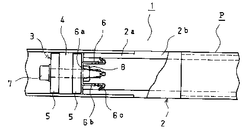
EMDODIMENT 1
Fig. 1 is a side elevational view with a broken part of the structure of the
pipe connection
effected with the pipe joint according to the present invention as stated in
Claim 1.
The pipe joint 1 of the present invention as stated in Claim 1 comprises a
joint body 2 consisting
of two insertion parts 2a connected in a straight line through a connection
part 2b, which consists of
a single cylinder having the same outer diameter with the pipes P. The joint
body 2 is made of a
synthetic resin material reinforced with glass fiber or a metal material such
as aluminum.
Numeral 3 designates a fixing device which, together with the joint body 2,
constitutes the pipe
joint of the present invention as stated in Claim 1, and consists of an
elastic member 4 of a circular
disc made of a material like urethane rubber having an outer diameter nearly
equal to the inner
diameter of pipe P, clamp discs 5, which are provided on both sides of the
elastic member 4 and have
approximately the same outer diameter with the elastic member 4, a stopper
piece 6, which is
positioned adjacent one of the clamp discs (on the left side in Fig. 2) and in
which a circular plate 6a
having a diameter smaller than the insertion parts 2a of the pipe joint body 2
is provided with legs
6b, which extend axially from a plurality of points (four points in Fig. 1 and
2) with increasing
diameter and have claws 6c formed by bending back the tips thereof outward in
such a manner that
the outer periphery thereof has a diameter slightly greater than the inner
diameter of the insertion
parts 2a and thereby the claws 6c are able to bite into the inner periphery of
the insertion parts 2a,
and a bolt 7 and a nut 8 lead through the center holes of the elastic member
4, the clamp discs 5 and
the stopper piece 6 to fasten them together. The fixing device 3 is mounted by
means of a tool
described hereinafter in the pipe P with the stopper piece 6 directed toward
the end thereof placed
at a position where the distance from the end of pipe P corresponds to the
length of the insertion
parts 2a.
CA 02544160 2006-04-28
which makes it possible to realize a strong resistance against pulling tension
without increasing the
contact length of the joint with the pipes, and to maintain the attractiveness
of the coupled pipes
without leaving through holes in the pipes and the joint, or any clearance in
the joint.
According to the pipe joint of the present invention as stated in Claim 2, one
end of the insertion
parts is pressed against the inner periphery of the pipe through a wedge
action due to the
displacement of the push pin caused by the turn of the elliptic pin, which
makes it possible to
realize a strong resistance against pulling tension without increasing the
contact length of the joint
with the pipes, and to maintain the attractiveness of the coupled pipes while
leaving but one
through hole in the pipe.
According to the pipe joint of the invention stated in Claim 3, in a way
similar to that of the
invention stated in Claim 2, one end of the insertion parts is pressed against
the inner periphery of
the pipe through a wedge action due to displacement of the push pin caused by
the turn of the
elliptic pin, which makes it possible to realize a strong resistance against
pulling tension without
increasing the contact length of the joint with the pipes, and to maintain the
attractiveness of the
coupled pipes while leaving but one through hole in the pipe.
According to the pipe joint of the invention stated in Claim 4, one end of
each of the insertion
parts is pressed against the inner periphery of the pipe through a wedge
action due to displacement
of the plurality of the push pins caused by the screwing-in of the push screw,
which makes it
possible to realize a strong resistance against pulling tension, without
increasing the contact length
of the joint with the pipes, and to maintain the attractiveness of the coupled
pipes since coupling of
a plurality of pipes can be effected by screwing a single push screw while
leaving but one through
hole in the pipe joint body.
PREFERRED EMBODIMENTS OF THE INVENTION
The joint bodies of the pipe joints according to the present invention as
stated in Claims 1
through 4 can be used in various configurations, such as a straight line type,
an L-shape type, a
T-shape type or a cross type, to connect 2 to 5 pipes together without
restricting the angle between
adjacent pipes to a right angle. The joint bodies of the pipe joints according
to the present
invention as stated in Claims 1 through 4 are made of synthetic resin
reinforced with glass fiber or
of a metal material such as aluminum.
A material such as urethane rubber is used as the elastic member in the fixing
device of the pipe
joint according to the present invention as stated in Claim 1. The stopper
piece of the fixing device
is made of a metal of relatively high hardness. For mounting the fixing device
in the pipe, the
fixing device is inserted to a position from the end of the pipe approximately
corresponding to the
length of the insertion part of the joint body with the stopper piece directed
toward the end, and an
appropriate tool for turning screws or nuts is used.
According to the present invention as stated in Claim 3, the pin hole of the
push pin in the pipe
joint is placed at a position slightly shifted toward the head portion from
the pin hole of the
insertion part at the beginning of the engagement between the push pin and the
taper of the
insertion part, and in this condition, the both pin holes make an ellipse of
which the longer axis is
CA 02544160 2006-04-28
6
To connect pipes P using the pipe joint 1 of the present invention as stated
in Claim 1, as shown
in Fig. 3, first at one end of a rod 9 (the left end in Fig. 3) a box is
provided 10, which fits on a nut 8,
and a stopper 11, which fits in the end of the pipe P and hits against the end
surface of the pipe P to
position the fixing device at a distance from the end of the pipe
corresponding to the length of the
insertion part 2a of the joint body is provided on the rod 9. Using the tool
13 which is further
provided with a handle 12 on the other end, the fixing device 3 is placed at
the predetermined
position in the pipe P, the bolt 7 and nut 8 are fastened by turning the
handle 12, which makes the
elastic disc 4 expand radially and press against the inner periphery of the
pipe P and thereby fixes
the fixing device 3 in the pipe P. Next, as the insertion part 2a of the joint
body 2 is inserted in the
end of the pipe P, the bent back claws 6c of the stopper piece 6 are first
compressed inwardly and
then bite into the inner periphery of the insertion part 2a thereby fixing the
insertion part 2a there.
Figs. 4 and 5 are a side section view and a partly broken side elevational
view respectively
showing the second and the third embodiments of the structure of the pipe
connection effected using
the second and the third modifications of the pipe joint of the present
invention as stated in Claim
1.
In the first modification 1' of the pipe joint 1 of the present invention as
stated in Claim 1, the
first embodiment has the connection part 2b of the joint body 2 consisting of
a single cylinder
having the same outer diameter as the pipe P, including a connection part 2b'
of the joint body 2'
consisting of also a single cylinder which is but bent in L shape. The second
modification 1" includes
as a connection part 2b" of the joint 2" a T-shaped structure consisting of
three cylinders having the
same outer diameter as the pipe P. Since the other structures and actions are
similar to those of
the pipe joint 1 of the present invention as stated in Claim l, the same
reference symbols are given
to the corresponding members and the description of them is omitted.
In the above described embodiments and modifications, the nut 8 of the fixing
device 3 is
described to be provided on the side of the stopper piece 6, however this is
not a restriction, and the
other arrangement wherein the bolt head is on the side of the stopper piece 6
is also possible. In
this case, at the end of the rod 9 of the tool 13, an engaging portion that
engages with a hexagonal
recess of the bolt 7 is be provided. Further, the bolt 7 of the fixing device
3 with a hexagonal recess
may be replaced by a bolt or a screw with a hexagonal head, providing a
corresponding engaging
portion on the tool 13 that engages with the head. Moreover, the connection
part 2b, 2b' or 2b" of
the joint body 2, 2' or 2" is not limited in construction to a straight type,
an L-shape type or a
T-shape type a cross type or a cross type having an additional pipe
perpendicular thereto can also
be employed.
EMDODIMENT 2
Fig. 6 is a side elevational view with a broken part showing the structure of
the pipe connection
effected with the pipe joint according to the present invention as stated in
Claim 2, Fig. 7 is a view
seen in the direction of VII-VII arrows of Fig. 6 and Fig. 8 is a diagonal
view of disassembled
members of the structure of Fig. 6.
The pipe joint 14 of the present invention as stated in Claim 2 comprises a
joint body 18
CA 02544160 2006-04-28
7
consisting of insertion parts 18a which, having a cylindrical form to be
fitted in the ends of the pipes
P, are formed on the inner periphery of one end thereof with a taper 15 that
decreases in diameter
toward the other end, on the same end are formed with a number of axially
extending slits 16, are
further provided with a through pin hole 17 perpendicular to the axis thereof,
and are connected
together in a straight line at the other ends thereof through a connection
part 18b consisting of a
single cylinder having the same outer diameter as the pipe P. This joint body
18 is made of a
synthetic resin material reinforced with glass fiber or a metal material such
as aluminum.
In the insertion part 18a is fitted a push pin 20 which, having cylindrical
form, is formed at the
outer end with a head portion 20a having a taper 19, which engages with the
taper 15 of the
insertion part 18a and which is provided with a through pin hole 21
corresponding to the pin hole
17 of the insertion part 18a. The pin hole 21 of the push pin 20 is placed at
a position slightly
shifted toward the head portion 20a from the pin hole of the insertion part
18a at the beginning of
engagement between the taper 19 of the push pin 20 and the taper 15 of the
insertion part 18a, and
in this condition, the both pin holes 17, 21 make an ellipse of which the
longer axis is perpendicular
to the axes of the push pin 20 and the pin holes 17, 21.
In the pin holes 17, 21 of the insertion part 18a and the push pin 20, which
is fitted in the
insertion part 18a, is inserted an elliptical pin 23 which, having an elliptic
cylindrical form, is
provided at the center of one end thereof with a hexagonal recess 22 and is
turned to shift the push
pin 20 in the axial direction of the insertion part 18a. The elliptical pin 23
has a length slightly
smaller than the outer diameter of the insertion part 18a, and through a turn
of about 90 degrees,
this pin 23 shifts the push pin 20 by about lmm, which aligns the pin holes 17
and 21 and presses
one end of the insertion part 18a against the inner periphery of the pipe P.
To connect pipes using the pipe joint 14 of the present invention as stated in
Claim 2, first, as
shown in Fig. 6, the insertion part 18a is inserted in the end of the pipe P.
Next, via a through hole
24 provided in the end portion of the pipe P corresponding to the pin hole 17,
a hexagonal wrench is
inserted to engage with the hexagonal recess 22 of the elliptical pin 23, and
the elliptical pin 23 is
turned about 90 degrees which shifts the push pin outwardly by about lmm and
one end of the
insertion part 18a is pressed against the inner periphery of the pipe P.
In Figs. 6 and 7, numeral 26 designates a cap to close the through hole 24 of
the pipe P.
Figs. 9 and 10 are a side section view and a partly broken side elevational
view, respectively,
showing the second and the third embodiments of the structure of the pipe
connection effected using
the second and the third modifications of the pipe joint of the present
invention as stated in Claim
2.
The first modification 14' of the pipe joint 14 of the present invention as
stated in Claim 2,
whereas the first embodiment has the connection part 18b of the joint body 18
consisting of a single
cylinder having the same outer diameter as the pipe P, includes a connection
part 18b' of the joint
body 18' consisting of also a single cylinder that is bent in an L shape. The
second modification 14"
includes as a connection part 18b" of the joint 18", a T-shaped structure
consisting of three cylinders
having the same outer diameter as the pipe P. Since the other structures and
actions are similar to
those of the pipe joint 14 of the present invention as stated in Claim 2, the
same reference symbols
CA 02544160 2006-04-28
' '
are given to the corresponding members and the description of them is omitted.
The connection part 18b, 18b' or 18b" of the joint body 18, 18' or 18" is not
limited in construction
to a straight type, an L-shape type or a T-shape type a cross type or a cross
type having an
additional pipe perpendicular thereto can also be employed.
EMDODIMENT 3
Figs. 17., 12 and 13 are respectively a side elevational view with a broken
part to show structure of
the pipe connection effected with the pipe joint according to the present
invention as stated in
Claim 3, a view seen in the direction of XB-XQ arrows of Fig. 11 and a
diagonal view of the
disassembled members of the structure of Fig. 11.
The pipe joint 27 of the present invention as stated in Claim 3 comprises a
joint body 29
consisting of insertion parts 29a, which, having a cylindrical form to be
fitted in the ends of the
pipes P, are formed on one end thereof with a number of axially extending
slits 28, and which are
connected together in a straight line at the other ends thereof through a
connection part 29b
consisting of a single cylinder having the same outer diameter as the pipe P.
This joint body 29 is
made of a synthetic resin material reinforced with glass fiber or a metal
material such as
aluminum.
In the insertion part 29a of the joint body 29 is fitted an insertion part 32a
which is formed on
the inner periphery at the inner end thereof with a taper 30 which decreases
in diameter toward the
outer end, and is formed on the same inner side thereof a number of slits 31,
and further at the
outer end of the insertion part 32a is provided with a stopper portion 32b
having a diameter slightly
smaller than the pipe P. On the stopper portion 32b is fitted a sleeve 32
having a through hole 33
perpendicular to the axis thereof. The sleeve 32 is a solid member made of a
synthetic resin
reinforced with glass fiber.
In the sleeve 32 a push pin 35 is inserted, which, having a cylindrical form,
is formed a head
portion 35a having at the inner end thereof a taper 34 to engage with the
taper 30 of the sleeve 32
and is provided on the outer end side with a through pin hole 36 perpendicular
to the axis thereof
corresponding to the pin hole 33. The pin hole 36 of the push pin 35 is placed
at a position slightly
shifted toward the head portion 35a from the pin hole 33 of the sleeve 32 at
the beginning of
engagement between the taper 34 of the push pin 34 and the taper 30 of the
sleeve 32 and in this
condition, the both pin holes 36, 33 make an ellipse of which the longer axis
is perpendicular to the
axes of the push pin 35 and the pin holes 36, 33.
In the pin holes 33 and 36, respectively, of the sleeve 32 fitted in the
insertion part 29a of the
joint body 29 and of the push pin 35 inserted in the sleeve 32, an elliptical
pin 38 is set, which,
having the form of an elliptical cylinder, is provided at the center of one
end thereof with a
hexagonal recess 37 and is turned to shift the push pin in the axial direction
of the sleeve. The
elliptical pin 38 has a length slightly smaller than the outer diameter of the
insertion part 29a. And,
through a turn of about 90 degrees, this pin 38 shifts the push pin 35 by
about lmm, which brings
the longer axis of the ellipse into alignment with the pin holes 33 and 26 of
the sleeve 32 and the
push pin 35 and presses one end of the insertion part 29a against the inner
periphery of the pipe P.
CA 02544160 2006-04-28
9
To connect pipes using the pipe joint 27 of the present invention as stated in
Claim 3, first, as
shown in Fig. 11, the insertion part 29a is inserted in the end of the pipe P.
Next, via a through
hole 39 provided in the end portion of the pipe P corresponding to the pin
hole 33 of the sleeve 32, a
hexagonal wrench is inserted to engage with the hexagonal recess 37 of the
elliptical pin 38, and the
elliptical pin 38 is turned about 90 degrees which shifts the push pin
outwardly by about lmm and
one end of the insertion part 29a is pressed against the inner periphery of
the pipe P.
In Fig. 12, numeral 41 designates a cap to close the through hole 39 of the
pipe P.
The connection part 29b of the joint body 29 is not limited in construction to
a straight type, but
can be of an L-shape type, a T-shape type, a cross type or a cross type having
an additional pipe
perpendicular thereto.
EMDODIMENT 4
Figs. 14 and 15 are, respectively, a side elevational view with a broken part
to show the
structure of the pipe connection effected with the pipe joint according to the
present invention as
stated in Claim 4, and a diagonal view of the disassembled members of the
structure of Fig. 14.
The pipe joint 42 of the present invention as stated in Claim 4, as shown in
detail in Fig. 16,
comprises a joint body 45 consisting of insertion parts 45a, which, having a
cylindrical form to be
fitted in the ends of the pipes P, are formed on one end thereof with a number
of axially extending
slits 43, are further provided on the same end side with a dowel hole 44 and
are connected at the
other ends in a straight line thxough a connection part 45b, which, consisting
of a single cylinder
having the same outer diameter as the pipe P, is provided at the mid point of
the axis of the single
cylinder a holder hole 46. This joint body 45 is made of a synthetic resin
material reinforced with
glass fiber or a metal material such as aluminum.
In the insertion part 45a a sleeve 47 is fitted having the form of a cylinder
with a bottom, the
bottom being the outer end thereof. In the bottom of the sleeve 47 a through
hole 48 is provided
and on the outer end side a number of axially extending slits 49 are formed,
and further on the
outer end side periphery thereof a dowel 50 is formed to protrude and engage
with the dowel hole 44
of the joint body 45. The dowel 50 of the sleeve 47 serves the purpose of
preventing the sleeve 47
from dropping away from the joint body 45 and is slightly inclined inwardly
The sleeve 47 is a
solid member made of synthetic resin reinforced with glass fiber.
In the sleeve 47 a push pin 53 is inserted, which, having a cylindrical form,
has a taper 51
formed on the periphery of the outer end thereof to engage with the through
hole 48 and also has a
protrusion 52, with a pointed tip, formed at the center of the inner end
thereof. The protrusion 52
of the push pin 53 may have a flat tip of small diameter.
As shown in detail in Fig. 17, in the holder hole 46 is fitted with a push
screw holder 54, which,
having a cylindrical form, has formed at the inner end thereof a stopper
portion 54a having a
diameter greater than that of the holder hole 46, and also has formed at the
center a threaded hole
55, the stopper portion 54a being chamfered to have a hexagonal peripheral.
The shape of the
peripheral of the stopper portion 54a of the holder 54 is not limited to a
hexagonal shape.
A push screw 58 is screwed in the threaded hole 55 of the push screw holder
54, and the push
CA 02544160 2006-04-28
1~
screw 58 has a hexagonal recess 56 formed at its outer end center, and has a
pointed tip 57 at its
inner end, which, having a greater diameter, hits against the protrusion of
the push pin 53 inserted
in the sleeve 47, which in turn is fitted in the insertion part 45a of the
joint body 45 to shift the push
pin 53 in the direction of the axis of the sleeve 47.
To connect pipes using the pipe joint 42 of the present invention as stated in
Claim 4, first, as
shown in Fig. 14, the insertion part 45a of the joint body 45 is inserted in
the end of the pipe P.
Next, by means of a hexagonal wrench, (not shown), which engages with the
hexagonal recess 56,
the push screw 58 is screwed in. Then, the push pin 53 is shifted outwardly by
about lmm and
with the effect of the taper 51 the through hole 48 of the sleeve 47 is spread
out thereby pressing
simultaneously the far side end portions of the both insertion parts 54a
against the inner periphery
of the pipes P.
Figs. 18 and 19 are a side section view and a partly broken side elevational
view, respectively,
showing the second and the third embodiments of the structure of the pipe
connection effected using
the first and the second modifications of the pipe joint of the present
invention as stated in Claim 4.
In the first modification 42' of the pipe joint 42 of the present invention as
stated in Claim 4, the
first embodiment has the connection part 45b of the joint body 45 consisting
of a single cylinder
having the same outer diameter as the pipe P, and includes a connection part
45b' of the joint body
45' also consisting of a single cylinder that is bent in L shape. The second
modification 42" includes
as a connection part 45b" of the joint body 45" a T-shaped structure
consisting of three cylinders
having the same outer diameter as the pipe P. The holder hole 46 of the joint
body 45' or 45" is
provided in a direction in which the axis thereof crosses the intersection of
the axes of the cylinders.
Since the other structures and actions are similar to those of the pipe joint
14 of the present
invention as stated in Claim 2, the same reference symbols are given to the
corresponding members
and the description of them is omitted.
The connection part 45b, 45b' or 45b" of the joint body 45, 45' or 45" is not
limited in construction
to a straight type, an L-shape type or a T-shape type a cross type or a cross
type having an
additional pipe perpendicular thereto can also be employed.
BIEF DESCRIPTION OF THE DRAWINGS
Fig. 1 is a partly broken side elevational view of the structure of the pipe
connection effected with
the pipe joint according to the present invention as stated in Claim 1~
Fig. 2 is a diagonal view showing the disassembled members of the fixing
device according to the
present invention as stated in Claim 1~
Fig. 3 is an illustration of the operation to fit the fixing device of the
pipe joint according to the
present invention as stated in Claim 1 in the end of a pipe
Fig. 4 is a side section view of the structure of the pipe connection effected
with the first
modification of the pipe joint according to the present invention as stated in
Claim l~
Fig. 5 a partly broken side elevational view of the structure of the pipe
connection effected with
the second modification of the pipe joint according to the present invention
as stated in Claim 1~
Fig. 6 is a partly broken side elevational view of the structure of the pipe
connection effected with
CA 02544160 2006-04-28
11
the pipe joint according to the present invention as stated in Claim 2~
Fig. 7 is a sectional view take in the direction of Vd-Vd arrows of Fig. 6~
Fig. 8 is a diagonal view showing the disassembled members of the connection
structure of Fig. 6~
Fig. 9 is a side section view of the structure of the pipe connection effected
with the first
modification of the pipe joint according to the present invention as stated in
Claim 2~
Fig. 10 is a partly broken side elevational view of the structure of the pipe
connection effected
with the second modification of the pipe joint according to the present
invention as stated in Claim
2~
Fig. 11 is a partly broken side elevational view of the structure of the pipe
connection effected
with the pipe joint according to the present invention as stated in Claim 3~
Fig. 12 is a sectional view take in the direction of XB-XB arrows of Fig. 11~
Fig. 13 is a diagonal view showing the disassembled members of the connection
structure of Fig.
11~
Fig. 14 is a partly broken side elevational view of the structure of the pipe
connection effected
with the pipe joint according to the present invention as stated in Claim 4~
Fig. 15 is a diagonal view showing the disassembled members of the connection
structure of Fig.
14~
Fig. 16 a diagonal view showing the disassembled members of the pipe joint of
the present
invention as stated in Claim 4~
Fig. 17 is a vertical section view showing the push screw holder and the push
screw assembled
together
Fig. 18 is a side section view of the structure of the pipe connection
effected with the first
modification of the pipe joint according to the present invention as stated in
Claim 4~ and
Fig. 19 is a partly broken side elevational view of the structure of the pipe
connection effected
with the second modification of the pipe joint according to the present
invention as stated in Claim
4.
LIST OF REFERENCE NUMERALS
1, 1', 1": pipe joint
2, 2', 2": joint body
2a: insertion part
2b, 2b', 2b": connection part
3: fixing device
4: elastic member
5: clamp disc
6: stopper piece
6a: circular plate
6b: leg
7: bolt
8: nut
. CA 02544160 2006-04-28
12
11: stopper
14, 14', 14": pipe joint
15: taper
16: slit
17: pin hole
18, 18', 18": joint body
18a: insertion part
18b, 18b', 18b": connection part
19: taper
20: push pin
20a: head portion
21: pin hole
22: hexagonalrecess
23: elliptical pin
27: pipe joint
28: slit
29: joint body
29a: insertion part
29b: connection part
30: taper
31: slit
32: sleeve
32a: insertion part
32b: stopper portion
33: pin hole
34: taper
35: push pin
35a: head portion
36: pin hole
37: hexagonal recess
38: elliptical pin
42, 42', 42": pipe joint
43: slit
44: dowel hole
45, 45', 45": joint body
46: holder hole
47: sleeve
48: through hole
49: slit
50: dowel
CA 02544160 2006-04-28
13
51: taper
52: protrusion
53: push pin
54: push pin holder
54a: stopper portion
55: threaded hole
56: hexagonalrecess
57: pointed tip
58: push screw
P: pipe