Language selection

Search

Patent 2544282 Summary

Third-party information liability

Some of the information on this Web page has been provided by external sources. The Government of Canada is not responsible for the accuracy, reliability or currency of the information supplied by external sources. Users wishing to rely upon this information should consult directly with the source of the information. Content provided by external sources is not subject to official languages, privacy and accessibility requirements.

Claims and Abstract availability

Any discrepancies in the text and image of the Claims and Abstract are due to differing posting times. Text of the Claims and Abstract are posted:

  • At the time the application is open to public inspection;
  • At the time of issue of the patent (grant).
(12) Patent Application: (11) CA 2544282
(54) English Title: MOVING SYSTEM FOR A CABLEWAY PLANT COMPRISING TWO HAULING CABLES
(54) French Title: SYSTEME MOBILE POUR INSTALLATIONS DE CABLES AERIENS COMPRENANT DEUX CABLES DE TRACTION
Status: Deemed Abandoned and Beyond the Period of Reinstatement - Pending Response to Notice of Disregarded Communication
Bibliographic Data
(51) International Patent Classification (IPC):
  • B61B 12/10 (2006.01)
  • B61B 12/12 (2006.01)
(72) Inventors :
  • LEVI, FERRUCCIO (Italy)
(73) Owners :
  • HIGH TECHNOLOGY INVESTMENTS B.V.
(71) Applicants :
  • HIGH TECHNOLOGY INVESTMENTS B.V.
(74) Agent: MARKS & CLERK
(74) Associate agent:
(45) Issued:
(22) Filed Date: 2006-04-20
(41) Open to Public Inspection: 2006-11-03
Availability of licence: N/A
Dedicated to the Public: N/A
(25) Language of filing: English

Patent Cooperation Treaty (PCT): No

(30) Application Priority Data:
Application No. Country/Territory Date
MI2005A 000800 (Italy) 2005-05-03

Abstracts

English Abstract


Simplified regulation and balancing system applicable
to cableway plants, of the continuous or to-and-fro
type, equipped with two hauling cables functioning in
parallel.
In a system according to the invention, the two cables
are moved by distinct pulleys with separate winches;
the kinematic chains of the two winches however are
connected to each other by a device which is
structurally similar to a car differential, whose outer
box is kept blocked during normal functioning. In this
way, the two winches are mechanically constrained and
can rotate only at the same speed.
By rotating the differential box with an external
system, a corresponding difference in the rotation rate
is actuated between the two motor shafts; the rotation
can take place, for example, with a small balancing
motor-reducer which activates a toothed crown integral
with the box.


Claims

Note: Claims are shown in the official language in which they were submitted.

-8-
CLAIMS
1. An aerial or ground cableway plant, of the
continuous, intermittent or back-and-fro type,
wherein the vehicles are moved by at least two
hauling pulleys which can also depend on a single
cable ring, characterized in that the two hauling
pulleys are moved by separate winches, but
connected by a mechanical device capable of
causing a small difference in velocity between the
two winches, positive or negative, according to
the commands of a suitable feedback signal, or
preventing a difference in velocity caused by
external factors.
2. The cableway plant according to claim 1,
characterized in that said mechanical device
consists of a system which is structurally similar
to a common car differential, whose outer box can
be rotated by suitable motorization, or blocked by
a braking system.
3. The plant according to claim 2, characterized in
that said motorization comprises at least one
reducer of the irreversible type, capable of also
acting as a blocking device when not fed.
4. The plant according to claim 2 or 3, characterized
in that said motorization is activated on the

-9-
basis of a feedback signal coming from a variation
in the asset of the vehicles, measured directly on
the vehicle.
5. The plant according to claim 2 or 3, characterized
in that said motorization is activated on the
basis of a feedback signal coming from a variation
in the asset of the vehicles, measured upon
arrival at the station.
6. The plant according to claim 2 or 3, characterized
in that said motorization is activated on the
basis of a feedback signal coming from the
velocity measurement of the cables in one of the
stations.
7. The plant according to claim 2 or 3, characterized
in that said motorization is activated on the
basis of a combination of feedback signals
according to the previous claims 4, 5, 6.
8. The plant according to any of the previous claims,
characterized in that said mechanical device is
inserted between the rapid shafts of the reducers
of two winches.
9. The plant according to any of the previous claims,
characterized in that said mechanical device is
activated by one or more variable speed electric
motors, of the direct or alternate current type.

-10-
10. The plant according to any of the previous claims,
characterized in that the motorization of said
mechanical device is regulated with respect to the
torque and/or the angular speed so as to integrate
the regulation functions of the main motors.

Description

Note: Descriptions are shown in the official language in which they were submitted.


CA 02544282 2006-04-20
-1-
MOVING SYSTEM FOR A CABLEWAY PLANT COMPRISING TWO
HAULING CABLES
The present invention relates to a simplified
regulation and balancing system which can be applied to
cableway plants, of the continuous or to-and-fro type,
equipped with two hauling cables functioning in
parallel.
Known plants of this type are, for example,
systems currently called DMC and FUNITEL, corresponding
to EP0093680, both of the continuous type; normal to-
and-fro cableways can also be equipped with two hauling
cables, as also other future types of plants.
In the presence of two hauling cables, in
particular in aerial plants, the problem arises of the
speed synchronization and the torque distribution
between the two cables; a difference in speed, in fact,
even if extremely small, when prolonged with time,
would sooner or later cause an irregular and
unacceptable asset of the vehicle.
Two systems are currently used for overcoming this
problem.
According to the first system, the two hauling
cables (which can also be only one cable ring which
effects two turns) are moved by a single winch equipped
with two driving pulleys integral with each other, or

CA 02544282 2006-04-20
-2-
by a single driving pulley with two races; this system
guarantees simply synchronization, provided that the
two integral races always have exactly the same
diameter; the system therefore requires control of the
diameter parity and the possibility of rapidly
intervening (for example by the turning of the race) in
the case of even a small variation due, for example, to
different wear of the washer.
This system also has the defect that, if there
1o were an accidental slippage of one of the two cables
with respect to the other, particular equipment is
necessary for reinstating the normal functioning, and
this reinstatement requires time during which the
passengers are compelled to remain immobile on the
line .
The second system comprises two completely
separate winches, and complex electronic equipment for
ensuring the regular running, with synchronization of
the speed and torque distribution; to ensure
2o synchronization also during the mechanical braking
phases (with electronic equipment which is not always
functioning) in this phase the two driving pulleys are
normally made mechanically integral with suitable
devices.
The electronic control equipment has currently

CA 02544282 2006-04-20
-3-
reached a high degree of functionality and reliability,
but this type of equipment is still complex and costly
and can cause breakdowns with consequent sudden
stoppages of the plant.
Furthermore, in spite of the reliability reached,
there is always the possibility of a sudden
malfunctioning and the plant must be dimensioned and,
in particular, the vehicles and line structures to deal
with all types of malfunctioning without danger for the
1o passengers.
An objective of the present invention is to obtain
a simple and reliable regulation system for plants of
this type, which allows economical synchronized
functioning without creating further potential
z5 breakdowns; the system also allows a simple and rapid
reinstatement of the correct configuration in the case,
for example, of slippage of the cables on one of the
races.
In a system according to the invention, the two
20 cables are moved by distinct pulleys with separate
winches; the kinematic chains of the two winches,
however, are advantageously connected with each other
in correspondence with the rapid shafts of the
reducers, by a device which is structurally similar to
25 a car differential, whose external box is kept blocked

CA 02544282 2006-04-20
-4-
during normal functioning. At this moment the two
winches are mechanically constrained and can only
rotate at the same rate.
By rotating the differential box with an external
system, a corresponding difference in the rotation rate
is actuated between the two motor shafts; the rotation
can take place, for example, with a small balancing
motor-reducer which activates a toothed crown integral
with the box.
l0 The final objective of the regulation system is to
ensure the running of the vehicles in normal asset,
i.e. without torsional or vertical veering due to the
surpassing of one cable with respect to the other; in
the system according to the invention the activation of
the balancing motor-reducer can be effected on the
basis of a feedback signal connected to the asset of
the vehicles; in particular:
~ in a system of the continuous type, such as DMC and
FUNITEL, a variation in the speed between the two
hauling pulleys (continuous or sudden) causes the
vehicles to arrive at the station with a progressively
increasing torsional inclination; this torsional
inclination can be easily measured by the station
equipment, and the relative signal is used to activate
the balancing motor-reducer which reinstates the

CA 02544282 2006-04-20
-5-
correct asset
~ in an intermittent system, or in any case equipped
with a limited number of large-dimensional vehicles
(normally 2), it is possible to verify the correct
asset of the vehicle with equipment on board the
vehicle itself, which sends the signal to the balancing
motor-reducer.
The motor-reducer which moves the differential box
is advantageously of the irreversible type (for example
l0 with a worm screw reducer) so that it also acts as a
rigid mechanical connecting system between the two
winches when velocity parity is guaranteed (for example
during the braking phases).
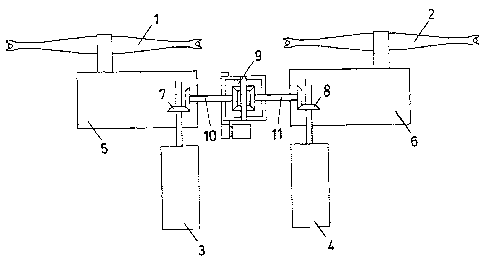
Figure 1 shows one of the possible lay-outs of a
s5 movement system according to the invention.
The two driving pulleys 1 and 2 are moved by
electric motors 3 and 4 with the interposition of
geared reducers 5 and 6; conical torques 7 and 8 are
inserted on the rapid shafts of the reducers.
2o A differential system 9, connected to the conical
torques of the reducers through the rapid shafts 10 and
11, is situated between the two reducers; the conical
torques are organized so that when the two pulleys move
the plant in the same direction, the two shafts 10 and
25 11 rotate in the opposite direction.

CA 02544282 2006-04-20
-6-
Figure 2 represents a detail of the differential
system 9, illustrating the external box 13 integral
with the satellite gears 12 and with the outer toothed
crown 14; the box can be rotated or blocked by the
irreversible motor-reducer 15 which acts on the toothed
crown 14.
When the rotation of the box 13 is blocked, the
rapid shafts 10 and 11, made integral by the satellites
12, compel the two motors 3 and 4 and the two pulleys 1
1o and 2 to rotate at the same velocity; if , on the other
hand, the box 13 is rotated with an angular velocity c~,
the angular velocity of one of the shafts is increased
by w/2 whereas that of the other is reduced by w/2.
During normal functioning, the satellite-holder
box 13 is usually kept blocked; if the two pulleys do
not have exactly the same diameter, however, the two
cables will move at a different rate and this is
revealed sooner or later by the control devices; these
send a feedback signal to the motor-reducer 15 which
2o causes the box 13 to rotate until the correct
functioning has been reinstated.
In general, the rotation speed of the motor-
reducer 15 corresponds to the difference in velocity of
the two motors 3 and 4, whereas the torque transmitted
corresponds to the torque difference between the same

CA 02544282 2006-04-20
_7_
motors; consequently, with a suitable regulation of the
motor-reducer 15, with respect to velocity and/or
torque, it is also possible to integrate or substitute
the normal regulation and balancing functions of the
main motors.

Representative Drawing
A single figure which represents the drawing illustrating the invention.
Administrative Status

2024-08-01:As part of the Next Generation Patents (NGP) transition, the Canadian Patents Database (CPD) now contains a more detailed Event History, which replicates the Event Log of our new back-office solution.

Please note that "Inactive:" events refers to events no longer in use in our new back-office solution.

For a clearer understanding of the status of the application/patent presented on this page, the site Disclaimer , as well as the definitions for Patent , Event History , Maintenance Fee  and Payment History  should be consulted.

Event History

Description Date
Application Not Reinstated by Deadline 2012-04-20
Time Limit for Reversal Expired 2012-04-20
Inactive: Abandon-RFE+Late fee unpaid-Correspondence sent 2011-04-20
Deemed Abandoned - Failure to Respond to Maintenance Fee Notice 2011-04-20
Application Published (Open to Public Inspection) 2006-11-03
Inactive: Cover page published 2006-11-02
Inactive: First IPC assigned 2006-08-03
Inactive: IPC assigned 2006-08-03
Application Received - Regular National 2006-05-29
Letter Sent 2006-05-29
Inactive: Filing certificate - No RFE (English) 2006-05-29

Abandonment History

Abandonment Date Reason Reinstatement Date
2011-04-20

Maintenance Fee

The last payment was received on 2010-03-22

Note : If the full payment has not been received on or before the date indicated, a further fee may be required which may be one of the following

  • the reinstatement fee;
  • the late payment fee; or
  • additional fee to reverse deemed expiry.

Patent fees are adjusted on the 1st of January every year. The amounts above are the current amounts if received by December 31 of the current year.
Please refer to the CIPO Patent Fees web page to see all current fee amounts.

Fee History

Fee Type Anniversary Year Due Date Paid Date
Registration of a document 2006-04-20
Application fee - standard 2006-04-20
MF (application, 2nd anniv.) - standard 02 2008-04-21 2008-03-17
MF (application, 3rd anniv.) - standard 03 2009-04-20 2009-03-26
MF (application, 4th anniv.) - standard 04 2010-04-20 2010-03-22
Owners on Record

Note: Records showing the ownership history in alphabetical order.

Current Owners on Record
HIGH TECHNOLOGY INVESTMENTS B.V.
Past Owners on Record
FERRUCCIO LEVI
Past Owners that do not appear in the "Owners on Record" listing will appear in other documentation within the application.
Documents

To view selected files, please enter reCAPTCHA code :


To view images, click a link in the Document Description column. To download the documents, select one or more checkboxes in the first column and then click the "Download Selected in PDF format (Zip Archive)" or the "Download Selected as Single PDF" button.

List of published and non-published patent-specific documents on the CPD .

If you have any difficulty accessing content, you can call the Client Service Centre at 1-866-997-1936 or send them an e-mail at CIPO Client Service Centre.


Document
Description 
Date
(yyyy-mm-dd) 
Number of pages   Size of Image (KB) 
Description 2006-04-19 7 201
Abstract 2006-04-19 1 24
Claims 2006-04-19 3 68
Drawings 2006-04-19 1 11
Representative drawing 2006-10-15 1 6
Courtesy - Certificate of registration (related document(s)) 2006-05-28 1 105
Filing Certificate (English) 2006-05-28 1 158
Reminder of maintenance fee due 2007-12-23 1 112
Reminder - Request for Examination 2010-12-20 1 119
Courtesy - Abandonment Letter (Maintenance Fee) 2011-06-14 1 173
Courtesy - Abandonment Letter (Request for Examination) 2011-07-26 1 164