Language selection

Search

Patent 2544773 Summary

Third-party information liability

Some of the information on this Web page has been provided by external sources. The Government of Canada is not responsible for the accuracy, reliability or currency of the information supplied by external sources. Users wishing to rely upon this information should consult directly with the source of the information. Content provided by external sources is not subject to official languages, privacy and accessibility requirements.

Claims and Abstract availability

Any discrepancies in the text and image of the Claims and Abstract are due to differing posting times. Text of the Claims and Abstract are posted:

  • At the time the application is open to public inspection;
  • At the time of issue of the patent (grant).
(12) Patent: (11) CA 2544773
(54) English Title: REINFORCED ENERGY ABSORBING BUMPER
(54) French Title: PARE-CHOCS AMORTISSEUR RENFORCE
Status: Granted and Issued
Bibliographic Data
(51) International Patent Classification (IPC):
  • B60R 19/18 (2006.01)
  • B60R 19/03 (2006.01)
(72) Inventors :
  • CONDEELIS, PAUL M. (United States of America)
(73) Owners :
  • ROMEO-RIM, INC.
(71) Applicants :
  • ROMEO-RIM, INC. (United States of America)
(74) Agent: GOWLING WLG (CANADA) LLP
(74) Associate agent:
(45) Issued: 2014-01-28
(22) Filed Date: 2006-04-21
(41) Open to Public Inspection: 2006-10-29
Examination requested: 2011-01-24
Availability of licence: N/A
Dedicated to the Public: N/A
(25) Language of filing: English

Patent Cooperation Treaty (PCT): No

(30) Application Priority Data:
Application No. Country/Territory Date
11/116,602 (United States of America) 2005-04-29

Abstracts

English Abstract

An energy absorbing bumper (10) includes a back plate (11) which is adapted to be attached to a vehicle. An elastomeric module (12) includes an impact face (13) and upper and lower rails (14, 15) extending from the impact face (13). One or more metallic inserts (30) are molded into the rails (14, 15). Each insert (30) includes a plurality of longitudinally extending, laterally spaced bars (31) which intersect a plurality of laterally extending, longitudinally spaced bars (32) to form adjacent rows of openings (33, 34). A fastener (17) extends through at least one of the openings (33, 34) in each insert (30) to attach the rails (14, 15) to the back plate (11). The inserts (30) minimize the possibility of shearing of the module (12) at the area of fasteners (17).


French Abstract

Un pare-chocs amortisseur (10) comprend une plaque arrière (11) qui est adaptée pour être fixée à un véhicule. Un module élastomérique (12) comprend une face d'impact (13) et des rails supérieur et inférieur (14, 15) s'étendant à partir de la face d'impact (13). Une ou plusieurs insertions métalliques (30) sont moulées dans les rails (14, 15). Chaque insertion (30) comprend une pluralité de barres espacées latéralement (31) s'étendant longitudinalement et croisant une pluralité de barres (32) espacées longitudinalement s'étendant latéralement pour former des rangées adjacentes d'ouvertures (33, 34). Une fixation (17) s'étend dans au moins une des ouvertures (33, 34) de chaque insertion (30) pour fixer les rails (14, 15) à la plaque arrière (11). Les insertions (30) minimisent la possibilité de cisaillement du module (12) dans la zone des fixations (17).

Claims

Note: Claims are shown in the official language in which they were submitted.

5
What is claimed is:
1. An energy absorbing bumper for a vehicle comprising a plate adapted to
be attached to the vehicle; an elastomeric module carried by said plate, said
module including an impact face and opposed rails extending from said impact
face; at least one metallic insert completely embedded in each rail, each said
insert having a plurality of adjacent openings extending completely through
said
insert; and at least one fastener to attach each rail to said plate, said
fastener
extending through one of said adjacent openings without engaging said insert.
2. The bumper of claim 1 wherein each said insert includes a plurality of
longitudinally extending, laterally spaced first bars and a plurality of
laterally
extending, longitudinally spaced second bars, said first and second bars
intersecting to form said openings.
3. The bumper of claim 2 wherein said first and second bars form a first
set
of longitudinally spaced openings positioned laterally adjacent to a second
set of
longitudinally spaced openings.
4. The bumper of claim 1 wherein each said opening is approximately the
size of said fastener so that said insert encapsulates said fastener.
5. The bumper of claim 1 wherein said insert is made of stainless steel.
6. The bumper of claim 1 wherein each said opening in said insert is
generally square.
7. The bumper of claim 6 wherein said fastener is a screw having a diameter
approximately the size of a side of each said opening.

6
8. An insert for a module of a bumper adapted to receive a fastener that
attaches the module to a plate of the bumper comprising a plurality of
metallic
bars forming a plurality of adjacent openings therebetween, the fastener
adapted
to be received within one of said adjacent openings.
9. The insert of claim 8 wherein said bars include a plurality of
longitudinally
extending, laterally spaced first bars and a plurality of laterally extending,
longitudinally spaced second bars, said first and second bars intersecting to
form
said openings.
10. The insert of claim 9 wherein said first and second bars form a first
set of
longitudinally spaced openings positioned laterally adjacent to a second set
of
longitudinally spaced openings.
11. The insert of claim 8 wherein said openings are approximately the size
of
the fastener so that the fastener is adapted to be encapsulated by said bars.
12. The insert of claim 8 wherein said bars are made of stainless steel.
13. The insert of claim 8 wherein said openings are generally square.
14. The insert of claim 13 wherein the size of a side of the square is made
to
generally correspond to the size of the fastener.

Description

Note: Descriptions are shown in the official language in which they were submitted.


CA 02544773 2006-04-21
Docket No. ROM.P0013
REINFORCED ENERGY ABSORBING BUMPER
TECHNICAL FIELD
This invention relates to an energy absorbing bumper for a vehicle.
More specifically, this invention relates to such a bumper which is molded of
a
elastomeric material with a metallic insert therein to resist torsional forces
and
prevent shearing of the elastomeric material.
BACKGROUND ART
Energy absorbing bumpers for vehicles, such as cars, buses or the
tike, are well known in the art. Most typically, such bumpers are made of an
elastomeric material, such as polyurethane or the like, and are at times
filled
with a foam or similar material. Usually these bumpers are provided in a
modular form and are attached, as by screws or other fasteners, to a metallic
back plate which is carried by the vehicle. Such bumpers are thus intended to
absorb energy of the contact of the vehicle with another structure, and
typically
they assure that no damage is done to the vehicle in a crash of up to five
miles
an hour. These bumpers are most prevalently found on buses.
While these bumpers thus satisfactorily cushion the force of direct
impacts, the prior art bumpers are inadequate when torsional forces are
involved. Such forces might be encountered, for example, if one vehicle is
pushing another vehicle, particularly around a street corner, or if other than
a
direct impact were encountered. In these instances, a lateral end of the
bumper may be exposed to a torsional force which can tear the module away
from the back plate at the area of the fasteners.
Thus, the need exists for an energy absorbing bumper which can
resist both direct and torsional forces.
DISCLOSURE OF THE INVENTION
It is thus an object of the present invention to provide an energy
absorbing bumper which can withstand both direct forces and torsional forces.

CA 02544773 2006-04-21
Docket No. ROM.P0013 2
It is another object of the present invention to provide an energy
absorbing bumper, as above, which resists tearing at the area of the
connection to the back plate when exposed to a torsional force.
These and other objects of the present invention, as well as the
advantages thereof over existing prior art forms, which will become apparent
from the description to follow, are accomplished by the improvements
hereinafter described and claimed.
In general, an energy absorbing bumper for a vehicle includes a
plate adapted to be attached to the vehicle. An elastomeric module is carried
by the plate and includes an impact face and opposed rails extending
therefrom. At least one metallic insert having at least one opening is
positioned
in each rail. At least one fastener extends through an opening in the insert
in
each rail to attach each rail to the plate.
In accordance with another aspect of the invention, an insert is
provided for a module of a bumper and is adapted to receive a fastener that
attaches the module to a plate of the bumper. The insert includes a plurality
of
metallic bars forming at least one opening therebetween. The fastener is
adapted to be received within the opening.
A preferred exemplary energy absorbing bumper made in
accordance to the concepts of the present invention is shown by way of
example in the accompanying drawings without attempting to show all the
various forms and modifications in which the invention might be embodied, the
invention being measured by the appended claims and not by the details of the
specification.
BRIEF DESCRIPTION OF THE DRAWINGS
Fig. 1 is perspective view of an insert which can be positioned within
an energy absorbing bumper.
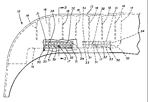
Fig. 2 is a fragmentary, top plan view of an energy absorbing bumper
showing two of the inserts of Fig. 1 positioned therein.
Fig. 3 is a sectional view taken substantially along line 3-3 of Fig. 2.

CA 02544773 2006-04-21
Docket No. ROM.P0013 ' 3
PREFERRED EMBODIMENT FOR CARRYING OUT THE INVENTION
A bumper made in accordance with the present invention is shown in
Figs. 2 and 3 and is indicated generally by the numeral 10. Bumper 10
includes a metallic back plate 11 which can be mounted in a conventional
manner to the front or rear of a vehicle. Back plate 11 carries an energy
absorbing bumper module generally indicated by the numeral 12. While the
exact nature of the material of module 12 is not critical to the present
invention,
a typical module 12 is made of an elastomeric material such as polyurethane.
Module 12 could be made as one integral unit, that is, the size of an entire
bumper for a vehicle. However, typically a bumper 10 is constructed with a
module 12 formed in at least three segments, two corner module segments
(one of which is shown in Fig. 2) and a central module segment having ends
which telescope within the ends of opposed corner module segments.
Module 12 includes a front impact face 13 which extends
longitudinally along the bumper 10 along one corner module, through the
central module, and along the other corner module. Impact face 13 thus
extends laterally across the vehicle to which bumper 10 is mounted. All
segments of module 12 include upper and lower rails 14 and 15, respectively.
To attach module 12 to back plate 11, the rear end of rails 14 and 15 are
received in slots 16 formed in back plate 11 and attached thereto by fasteners
17 which can be in the form of self-taping screws, bolts or the like. A
plurality
of fasteners 17 may be longitudinally spaced along bumper 10, two such
fasteners 17 being shown in Fig. 2. Module 12 can also include a plurality of
generally C-shaped vertical ribs 18 which enhance the energy absorption of
vehicle bumper 10, and which are spaced longitudinally within module 12.
Vertical ribs 18 extend rearwardly from impact face 13 and along upper and
lower rails 14 and 15. Module 12 is also shown as having upper and lower
wings 19 with reinforcing ribs 20 extending therefrom to upper and lower rails
14 and 15. These wings 19 are primarily for aesthetic purposes and generally
play no role in the energy absorbing characteristics of the system.
A bumper insert made in accordance with the present invention is
shown in Fig. 1 and is indicated generally by the numeral 30. Insert 30 is
preferably made of stainless steel and is formed by a plurality of
longitudinally

CA 02544773 2006-04-21
Docket No. ROM.P0013 4
extending, laterally spaced bars 31 which are intersected by a plurality of
laterally extending, longitudinally spaced bars 32. As a result, a plurality
of
longitudinally adjacent openings 33 are formed which are positioned laterally
adjacent to a second set of longitudinally adjacent openings 34.
One or more bumper inserts 30 may be positioned in each upper rail
14 and each lower rail 15. To that end, the inserts 30 to be included in
bumper
are positioned, where desired, in the mold from which bumper 10 is to be
manufactured, and the polyurethane material is molded around any insert 30
so positioned. The openings 33 and 34 are preferably the approximate size of
10 a fastener 17, and thus, as shown in Fig. 2, the fasteners 17 can extend
through an opening 33. While any number of inserts 30 could be provided
longitudinally along rails 14 and 15, their need is greatest in the corner
modules, and thus, it is preferred to provide inserts 30 only in the corner
modules of bumper 10, one of which is shown in Fig. 2.
When bumper 10 experiences other than a direct force, such as a
torsional force on a corner module, inserts 30 will tend to prevent the
shearing
or tearing problems at the location of fasteners 17 experienced by the prior
art.
In fact, it has been found that modules 12 equipped with an insert 30 can
generally withstand more than five times the force before shearing. This is
because each fastener is encapsulated within opposed pairs of bars 31 and
opposed pairs of bars 32. While the openings 33 and 34 are shown as being
square, other configurations, such as round, are contemplated by this
invention
as long as the fasteners are fully surrounded. When square, the size of a side
of an opening 33, 34 should approximate the diameter of the fastener 17.
Moreover, while an insert 30 could be provided with only one opening, by
providing insert 30 with multiple openings, the manufacturing process is
simplified. That is, the precise positioning of insert 30 in rails 14 and 15
is not
critical because if a fastener 17 does not find its way through one opening
33,
34, it will find its way through the next adjacent opening 33, 34.
It should thus be evident that a bumper 10 constructed as described
herein, with one or more inserts 30 imbedded therein, accomplishes the objects
of the present invention and otherwise substantially improves the art.

Representative Drawing
A single figure which represents the drawing illustrating the invention.
Administrative Status

2024-08-01:As part of the Next Generation Patents (NGP) transition, the Canadian Patents Database (CPD) now contains a more detailed Event History, which replicates the Event Log of our new back-office solution.

Please note that "Inactive:" events refers to events no longer in use in our new back-office solution.

For a clearer understanding of the status of the application/patent presented on this page, the site Disclaimer , as well as the definitions for Patent , Event History , Maintenance Fee  and Payment History  should be consulted.

Event History

Description Date
Inactive: COVID 19 - Deadline extended 2020-03-29
Common Representative Appointed 2019-10-30
Change of Address or Method of Correspondence Request Received 2018-01-10
Inactive: Late MF processed 2015-05-06
Letter Sent 2015-04-21
Grant by Issuance 2014-01-28
Inactive: Cover page published 2014-01-27
Pre-grant 2013-11-13
Inactive: Final fee received 2013-11-13
Notice of Allowance is Issued 2013-08-27
Letter Sent 2013-08-27
Notice of Allowance is Issued 2013-08-27
Inactive: Approved for allowance (AFA) 2013-08-23
Amendment Received - Voluntary Amendment 2013-08-09
Inactive: S.30(2) Rules - Examiner requisition 2013-02-11
Letter Sent 2011-02-01
Request for Examination Requirements Determined Compliant 2011-01-24
All Requirements for Examination Determined Compliant 2011-01-24
Request for Examination Received 2011-01-24
Application Published (Open to Public Inspection) 2006-10-29
Inactive: Cover page published 2006-10-29
Inactive: IPC assigned 2006-10-17
Inactive: First IPC assigned 2006-10-17
Inactive: IPC assigned 2006-10-17
Inactive: Filing certificate - No RFE (English) 2006-05-31
Filing Requirements Determined Compliant 2006-05-31
Letter Sent 2006-05-31
Application Received - Regular National 2006-05-31

Abandonment History

There is no abandonment history.

Maintenance Fee

The last payment was received on 2013-03-20

Note : If the full payment has not been received on or before the date indicated, a further fee may be required which may be one of the following

  • the reinstatement fee;
  • the late payment fee; or
  • additional fee to reverse deemed expiry.

Please refer to the CIPO Patent Fees web page to see all current fee amounts.

Owners on Record

Note: Records showing the ownership history in alphabetical order.

Current Owners on Record
ROMEO-RIM, INC.
Past Owners on Record
PAUL M. CONDEELIS
Past Owners that do not appear in the "Owners on Record" listing will appear in other documentation within the application.
Documents

To view selected files, please enter reCAPTCHA code :


To view images, click a link in the Document Description column. To download the documents, select one or more checkboxes in the first column and then click the "Download Selected in PDF format (Zip Archive)" or the "Download Selected as Single PDF" button.

List of published and non-published patent-specific documents on the CPD .

If you have any difficulty accessing content, you can call the Client Service Centre at 1-866-997-1936 or send them an e-mail at CIPO Client Service Centre.


Document
Description 
Date
(yyyy-mm-dd) 
Number of pages   Size of Image (KB) 
Description 2006-04-21 4 205
Abstract 2006-04-21 1 20
Claims 2006-04-21 2 66
Drawings 2006-04-21 2 59
Representative drawing 2006-10-04 1 11
Cover Page 2006-10-19 1 41
Drawings 2013-08-09 2 56
Claims 2013-08-09 2 63
Representative drawing 2013-12-27 1 12
Cover Page 2013-12-27 2 45
Maintenance fee payment 2024-03-05 25 1,011
Courtesy - Certificate of registration (related document(s)) 2006-05-31 1 105
Filing Certificate (English) 2006-05-31 1 158
Reminder of maintenance fee due 2007-12-24 1 112
Reminder - Request for Examination 2010-12-22 1 119
Acknowledgement of Request for Examination 2011-02-01 1 176
Commissioner's Notice - Application Found Allowable 2013-08-27 1 163
Maintenance Fee Notice 2015-05-06 1 170
Late Payment Acknowledgement 2015-05-06 1 163
Correspondence 2013-11-13 2 49
Fees 2015-05-06 1 27