Language selection

Search

Patent 2544938 Summary

Third-party information liability

Some of the information on this Web page has been provided by external sources. The Government of Canada is not responsible for the accuracy, reliability or currency of the information supplied by external sources. Users wishing to rely upon this information should consult directly with the source of the information. Content provided by external sources is not subject to official languages, privacy and accessibility requirements.

Claims and Abstract availability

Any discrepancies in the text and image of the Claims and Abstract are due to differing posting times. Text of the Claims and Abstract are posted:

  • At the time the application is open to public inspection;
  • At the time of issue of the patent (grant).
(12) Patent Application: (11) CA 2544938
(54) English Title: CONTINUOUSLY VARIABLE RATIO TRANSMISSION
(54) French Title: TRANSMISSION A VARIATION CONTINUE
Status: Deemed Abandoned and Beyond the Period of Reinstatement - Pending Response to Notice of Disregarded Communication
Bibliographic Data
(51) International Patent Classification (IPC):
  • F16H 37/08 (2006.01)
  • F16H 37/10 (2006.01)
(72) Inventors :
  • OLIVER, ROBERT ANDREW (United Kingdom)
  • FIELDING, ALAN (United Kingdom)
(73) Owners :
  • TOROTRAK (DEVELOPMENT) LIMITED
(71) Applicants :
  • TOROTRAK (DEVELOPMENT) LIMITED (United Kingdom)
(74) Agent: SMART & BIGGAR LP
(74) Associate agent:
(45) Issued:
(86) PCT Filing Date: 2004-11-10
(87) Open to Public Inspection: 2005-05-26
Availability of licence: N/A
Dedicated to the Public: N/A
(25) Language of filing: English

Patent Cooperation Treaty (PCT): Yes
(86) PCT Filing Number: PCT/GB2004/004736
(87) International Publication Number: WO 2005047736
(85) National Entry: 2006-05-05

(30) Application Priority Data:
Application No. Country/Territory Date
0326199.7 (United Kingdom) 2003-11-10

Abstracts

English Abstract


A continuously variable ratio transmission (CVT) comprises a ratio varying
unit ("variator"), a first epicyclic (18) having two inputs (A2, S2) connected
to opposite sides of the variator (V), a second. epicyclic (16) having an
input (C1) driven by a prime mover (12) and components (A1, S1) connected to
opposite sides of the variator, a final drive shaft (14), a low regime clutch
(L) for selectively connecting the output of the first epicyclic to the final
drive shaft in low regime and a third, mixing, epicyclic (20) connected to the
output (C2) of the first epicyclic (18) and connected or connectable (F, R) to
the variator and being connectible with the final drive shaft in high regime
by way of a high regime clutch (F). The high and low regimes are coincident at
at least one variator ratio (or, more preferably, the operation ranges
overlap) and the variator operates in opposite directions in the low and high
regimes.


French Abstract

Selon l'invention, une transmission à variation continue (CVT) comprend une unité de variation de rapport ("variateur"), un premier train épicycloïdal (18) présentant deux entrées (A2, S2) reliées à des côtés opposés du variateur (V), un deuxième train épicycloïdal (16) présentant une entrée (C1) entraînée par un moteur d'entraînement (12) et des composants (A1, S1) reliés aux côtés opposés du variateur, un arbre d'entraînement final (14), un mécanisme d'embrayage à bas régime (L) permettant de relier sélectivement la sortie du premier train épicycloïdal à l'arbre d'entraînement final à bas régime et un troisième train épicycloïdal (20), d'accouplement, relié à la sortie (C2) du premier train épicycloïdal (18) et relié ou pouvant être relié (F, R) au variateur et pouvant être relié à l'arbre d'entraînement final à haut régime au moyen d'un mécanisme d'embrayage à haut régime (F). Les haut et bas régimes coïncident à au moins un rapport du variateur (ou, mieux encore, les plages de fonctionnement se chevauchent) et le variateur fonctionne en sens opposés à haut et bas régimes.

Claims

Note: Claims are shown in the official language in which they were submitted.

CLAIMS
1, A continuously variable ratio transmission (CVT) comprising:
(a) a ratio varying unit ("variator");
(b) a first epicyclic having two inputs connected to opposite sides of the
variator:
(c) a second epicyclic having an input driven by a prime mover and
components connected to opposite sides of the variator:
(d) a final drive shaft;
(e) a low regime clutch for selectively connecting the output of the first
epicyclic to the final drive shaft in low regime;
(f) a third, mixing, epicyclic connected to the output of the first epicyclic
and
connected or connectable to the variator and being connectible with the final
drive
shaft in high regime by way of a high regime clutch;
wherein the high and low regimes are coincident at at least one variator ratio
and
the variator operates in opposite directions in the low and high regimes.
2. A continuously variable ratio transmission (CVT) as claimed in claim 1,
wherein the operation ranges of the high and low regimes overlap.
3. A continuously variable ratio transmission (CVT) comprising:
(a) a ratio varying unit ("variator");
7

(b) a first epicyclic having two inputs connected to opposite sides of the
variator:
(c) a second epicyclic having an input driven by a prime mover and
components connected to opposite sides of the variator:
(d) a final drive shaft connectible with the variator by way of one of two
alternative driven rotatable members connected to opposite sides of the
variator
respectively; and
a first clutch disposed between an output of the first epicyclic and the final
drive
shaft for selectively connecting the output of the first epicyclic to the
final drive
shaft:
the transmission further comprising:
a third, mixing, epicyclic disposed between at least one of the driven
rotatable
members and the final drive shaft and receiving inputs from the output of the
first
epicyclic and said driven rotatable shaft; and
a second clutch disposed between said one driven rotatable member and the
final
drive shaft for selectively connecting the said one driven rotatable member to
the
final drive shaft via the third epicyclic.
4. A CVT as claimed in claim 3, further comprising a third clutch disposed
between said other driven rotatable member and the final drive shaft for
selectively connecting the said other driven rotatable member to the final
drive
shaft via the third epicyclic.
8

5. A CVT as claimed in claim 4, wherein the second and third clutches are
disposed respectively between the said one driven rotatable member and the
third
epicyclic and between the said other driven rotatable member and the third
epicyclic.
6. A CVT as claimed in claim 3, further comprising:
a fourth epicyclic disposed between said other driven rotatable member and the
final drive shaft and receiving inputs from the output of the first epicyclic
and said
other driven rotatable shaft; and
a third clutch disposed between said other driven rotatable member and the
final
drive shaft for selectively connecting the said other driven rotatable member
to the
final drive shaft via the fourth epicyclic.
7. A CVT as claimed in claim 6, wherein the second and third clutches are
disposed respectively between the third epicyclic and the final drive shaft
and the
fourth epicyclic and the final drive shaft.
9

Description

Note: Descriptions are shown in the official language in which they were submitted.


CA 02544938 2006-05-05
WO 2005/047736 PCT/GB2004/004736
CONTINUOUSLY VARIABLE RATIO TRANSMISSION
The present invention relates to continuously variable ratio transmissions
("CVTs"). The invention is particularly applicable to such transmissions for
industrial or agricultural vehicles, for example tractors, which require a
very high
torque at low speeds and which often require the vehicle to be shuttled back
and
forth at low speeds, but which also have the requirement for lugh forward and
high xeverse regimes for higher speed, lower torque conditions.
In accordance with a first aspect of the present invention, there is provided
a continuously variable ratio transmission (CVT) comprising:
(a) a ratio varying unit ("variator"); .
(b) a ftrst epicyclic having two inputs connected to opposite sides of the
variator:
(c) a second epicyclic having an input driven by a prime mover and
components connected to opposite sides of the variator:
1s (d) a final drive shaft;
(e) a low regime clutch for selectively connecting the output of the first
epicyclic to the final drive shaft in low regime;
(f) a third, mixing, epicyclic connected to the output of the first epicyclie
and
connected or connectable to the variator and being connectible with the final
drive
2o shaft in high regime by way of a high regime clutch;
wherein the high and low regimes are coincident at at least one variator ratio
and
the variator operates in opposite directions in the low and high regimes.

CA 02544938 2006-05-05
WO 2005/047736 PCT/GB2004/004736
Preferably, the operation ranges of the high and low regimes overlap.
In accordance with a second aspect of the present invention there is
provided a continuously variable ratio transmission (CVT) comprising:
(a) a ratio varying unit ("variator");
(b) a first epicyclic having two inputs connected to opposite sides of the
variator:
(c) a second epicyclic having an input driven by a prime mover and
components connected to opposite sides of the variator:
(d) a final drive shaft comlectible with the variator by way of one of two
1o alternative driven rotatable members connected to opposite sides of the
variator
respectively; and
(e) a first clutch disposed between an output of the first epicyclic and the
final
drive shaft for selectively connecting the output of the first epicyelie to
the final
drive shaft:
the transmission further comprising:
a third, mixing, epicyclic disposed between at least one of the driven
rotatable
members and the final drive shaft and receiving inputs from the output of the
first
epicyclic and said driven rotatable shaft; and
a second clutch disposed between said one driven rotatable member and the fnal
2o drive shaft for selectively connecting the said one driven rotatable member
to the
final drive shaft via the third epicyclic.
2

CA 02544938 2006-05-05
WO 2005/047736 PCT/GB2004/004736
In one embodiment a tlurd clutch is disposed between said other driven
rotatable member and the final drive shaft for selectively connecting the said
other
driven rotatable merrxber to the final cliive shaft via the third epicyclic.
The second and third clutches are preferably disposed respectively
between the said one driven rotatable member and the third epicyclic and
between
the said other driven rotatable member and the third epicyclic.
In another embodiment, a fourth epicyclic isdisposed between said other
driven rotatable member and the final drive shaft and receiving inputs from
the
output of the first epicyclic and said othex driven rotatable shah: and
1 o a third clutch is disposed between said other driven rotatable member and
the .final
drive shaft fox selectively cormecting the said other driven rotatable member
to the
final drive shaft via the fourth epicyclic.
The second and third clutches are preferably disposed respectively
between the third epicyclic and the final drive shaft and the fourth epicyclic
and
the final drive shaft.
By way of example only, specific embodiments of the present invention
will now be described, with reference to the accompanying drawings, in which :-
Fig. 1 is a diagram~.natic representation of a first embodiment of CVT in
accordance with the present invention;
Fig. 2 is a representation of the transmission of Fig. l, which illustrates
the
transmission gearing in more detail;
Fig. 3 is a graph illustrating the operation of the first embodiment: and
3

CA 02544938 2006-05-05
WO 2005/047736 PCT/GB2004/004736
Fig. 4 is a diagrammatic representation of a second embodiment of CVT in
accordance with the present invention.
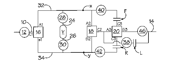
Referring to Figs. 1 and 2, a CVT has an input shaft 10, connected to a
prime mover via reduction gearing 12, an output shaft 14, a variator V of the
toroidal-race rolling traction type, an input epicyclic 16, a recirculating
epicyclic
18 and a mixing epicyclic 20. Reference numerals 24,26 indicate shafts
connected
to opposite sides of the variator V, which are connected via reduction gearing
28,30 to rotating members (hereinafter referred to as "shafts", fox
conveiuence)
32,34 wluch are in turn connected to two components (the annulus Al and the
sun
1 o gear S 1 respectively) of the input epicyclic 16, the remaining component
(the
planet carrier Cl) being connected to the input shaft 10.
The shafts 32,34 are also connected to two components (the annulus A2 and
the sun gear S2) of the recirculating epicyclic 18, the third component (the
planet
carrier C2) being connected by engagement of a low regime clutch L and via
reduction gearing 38 to the output shaft 14.
In addition, the shafts 32,34 are selectively and alternatively connectable
via
respective reduction gearing 40,42 and respective high regime forward and
reverse
clutches F,R to the same component (the planet carrier C3) of the mixing
epieyelic
20, another component (the annulus A3) of the epicyclic being permanently
2o connected to the output (the planet carrier C2) of the recirculating
epicyclic 18.
In low regime, the low regime clutch L is engaged and the high regime forward
and reverse clutches F,R are disengaged. In low regime, power recirculates
through the epicyclic 18 and, as shown in Fig. 3 by the line "Output L
engaged",
4

CA 02544938 2006-05-05
WO 2005/047736 PCT/GB2004/004736
as the variator V progresses from one end of its ratio range to the other the
speed
of the output shaft 14 can be arranged to make a continuous "low regime"
progression .from a finite maximum value in one direction, falling to zero and
then
climbing to a second maximum value in the opposite direction. In this way, the
transmission can shuttle easily between reverse and forward without having to
change regime. This is important for off highway vehicles such as tractors and
the like in which the transmission transmits high levels of torque at low
vehicle
speeds, during which it is preferable to avoid regime changes if possible.
It will also be seen from Fig. 3 that for each of a particular forward and
to reverse speed of the output shaft 14 there is a variator ratio
(approximately -0.68
and -2.74, correspondiizg to an ouput shaft speed of about 4,000 rpm) at which
the
output from the mixing epicyclic 20, if it were to be connected by the
respective
high regime forward or reverse clutch F,R, would be identical to the output
from
the mixing epicyclic 18 on engagement of the low regime clutch L, i.e. the two
inputs to the mixing epicyclic 20 would be identical. This is lcnown as
"synchronous ratio" and at that ratio the forward or reverse clutch F,R can be
engaged, depending on the direction of rotation of the output shaftJl4, and
the Iow
regime clutch L can be disengaged in order to place the transmission in a high
forward or high reverse regime as appropriate.
In higli forward or high reverse regime, as illustrated in. Fig. 3, the
variator
ratio is adjusted in the opposite direction as compared with low regime
operation
in order to increase the speed of the output shaft 14. In these regimes, the
drive of
one of the shafts 32, 34 is connected to the output shaft 14 via the engaged
clutch
5

CA 02544938 2006-05-05
WO 2005/047736 PCT/GB2004/004736
F or R, the mixing.epicyclic 20 (through the output component, sun gear S3)
and
reduction gearing 46.
!~ second embodiment is illustrated in Fig. 4. This is very similar to the
first
embodiment and the same reference numerals are used to describe corresponding
s features. The main difference is that the single mixing epi.cyclic 20 of the
first
embodiment is replaced with two mixing epicyclics 20', 20", a component (the
planet carrier) of each of which is connected to a respective one of the two
shafts
32,34, a fiu-ther component (the sun gear) of each of the epicyclics 20', 20"
being
selectively and alternatively connectible to the output shaft 14 via forward
and
t o reverse high regime clutches F,R respectively. In a similar manner to the
first
embodiment, the output of the recirculating epicyclic 18 is connected to a
component (the annulus) of each of the forward and reverse mixing epicyclics
20',
20" and is also connectable via a low regime clutch L to the output shaft 14.
When high forward or high reverse regime is required at synchronous ratio, the
15 appropriate forward or reverse clutch F,R is engaged and the low regime
clutch L
is disengaged to coimect the output of the appropriate mixing epicyclic 20',
20"
to the output shaft 14 via the reduction gearing.
The invention is not restricted to the details of the foregoing embodiments.
6

Representative Drawing
A single figure which represents the drawing illustrating the invention.
Administrative Status

2024-08-01:As part of the Next Generation Patents (NGP) transition, the Canadian Patents Database (CPD) now contains a more detailed Event History, which replicates the Event Log of our new back-office solution.

Please note that "Inactive:" events refers to events no longer in use in our new back-office solution.

For a clearer understanding of the status of the application/patent presented on this page, the site Disclaimer , as well as the definitions for Patent , Event History , Maintenance Fee  and Payment History  should be consulted.

Event History

Description Date
Application Not Reinstated by Deadline 2009-11-10
Time Limit for Reversal Expired 2009-11-10
Deemed Abandoned - Failure to Respond to Maintenance Fee Notice 2008-11-10
Inactive: IPRP received 2007-06-19
Letter Sent 2006-12-12
Inactive: Single transfer 2006-11-03
Inactive: Cover page published 2006-07-21
Inactive: Courtesy letter - Evidence 2006-07-18
Inactive: Notice - National entry - No RFE 2006-07-13
Application Received - PCT 2006-06-01
National Entry Requirements Determined Compliant 2006-05-05
Application Published (Open to Public Inspection) 2005-05-26

Abandonment History

Abandonment Date Reason Reinstatement Date
2008-11-10

Maintenance Fee

The last payment was received on 2007-11-06

Note : If the full payment has not been received on or before the date indicated, a further fee may be required which may be one of the following

  • the reinstatement fee;
  • the late payment fee; or
  • additional fee to reverse deemed expiry.

Please refer to the CIPO Patent Fees web page to see all current fee amounts.

Fee History

Fee Type Anniversary Year Due Date Paid Date
MF (application, 2nd anniv.) - standard 02 2006-11-10 2006-05-05
Basic national fee - standard 2006-05-05
Registration of a document 2006-11-03
MF (application, 3rd anniv.) - standard 03 2007-11-13 2007-11-06
Owners on Record

Note: Records showing the ownership history in alphabetical order.

Current Owners on Record
TOROTRAK (DEVELOPMENT) LIMITED
Past Owners on Record
ALAN FIELDING
ROBERT ANDREW OLIVER
Past Owners that do not appear in the "Owners on Record" listing will appear in other documentation within the application.
Documents

To view selected files, please enter reCAPTCHA code :


To view images, click a link in the Document Description column. To download the documents, select one or more checkboxes in the first column and then click the "Download Selected in PDF format (Zip Archive)" or the "Download Selected as Single PDF" button.

List of published and non-published patent-specific documents on the CPD .

If you have any difficulty accessing content, you can call the Client Service Centre at 1-866-997-1936 or send them an e-mail at CIPO Client Service Centre.


Document
Description 
Date
(yyyy-mm-dd) 
Number of pages   Size of Image (KB) 
Claims 2006-05-05 3 85
Description 2006-05-05 6 230
Representative drawing 2006-05-05 1 7
Drawings 2006-05-05 3 49
Abstract 2006-05-05 1 63
Cover Page 2006-07-21 1 43
Notice of National Entry 2006-07-13 1 192
Courtesy - Certificate of registration (related document(s)) 2006-12-12 1 106
Courtesy - Abandonment Letter (Maintenance Fee) 2009-01-05 1 173
Reminder - Request for Examination 2009-07-13 1 116
PCT 2006-05-05 4 141
PCT 2006-05-05 1 41
Correspondence 2006-07-13 1 27
PCT 2007-06-19 5 202
Fees 2007-11-06 1 40