Note: Descriptions are shown in the official language in which they were submitted.
CA 02545245 2006-05-08
WO 2005/056116 PCT/US2004/040248
-1-
MAN-RATED FIRE SUPPRESSION SYSTEM
TECHNICAL FIELD
The present invention relates to a fire suppression system. More specifically,
the present invention relates to a fire suppression system suitable for use in
occupied or
clean environments.
BACKGROUND
A fire involves a chemical reaction between oxygen and a fuel that is raised
to
its ignition temperature by heat. The fire is extinguished by removing oxygen,
reducing a temperature of the fire, separating the oxygen and the fuel, or
interrupting
chemical reactions of the combustion. Halogen-containing agents, such as Halon
agents, are chemical agents that have been effectively used to suppress or
extinguish
fires. These halogen-containing agents generate chemically reactive halogen
radicals
that interfere with combustion processes in the fire. However, many Halon
agents,
such as Halon 1211, Halon 1301, and Halon 2402, have been suggested to
contribute to the destruction of stratospheric ozone in the atmosphere, which
has led
many countries to ban their use. Therefore, effective fire fighting
replacements for
Halon agents are being developed. For instance, fire suppression systems have
been
recently developed to extinguish fires in enclosed spaces. These fire
suppression
systems introduce a flow of inert gas into the enclosed space to extinguish
the fire.
Some fire suppression systems use a source of compressed gas as the inert gas.
However, the compressed gas requires a large storage area, which adds
additional bulk
and hardware to the fire suppression system.
Other fire suppression systems have utilized a propellant to generate the
inert
gas. The propellant is ignited to generate the inert gas, which is then used
to extinguish
the fire. The inert gas typically includes nitrogen, carbon dioxide (CO2), or
water.
Some propellants used in fire suppression systems produce up to 20% by volume
of
CO2. While CO2 is a nonflammable gas that effectively extinguishes fires,
propellants
that generate copious amounts of CO2 cannot be used to extinguish fires in a
human-occupied space because CO2 is physiologically harmful. CO2 has an
Immediately Harmful to Life or Health (IDLH) value of a concentration of 4% by
CA 02545245 2006-05-08
WO 2005/056116 PCT/US2004/040248
-2-
volume and causes the human breathing rate to quadruple at levels from 4% by
volume
to 5% by volume, loss of consciousness within minutes at levels from 5% by
volume
to 10% by volume, and death by asphyxiation with prolonged exposure at these
or
higher levels. In addition, it is difficult to produce CO2 by combustion
without
producing significant amounts of carbon monoxide (CO), which has an IDLH of
0.12% by volume (i.e., 1200 parts per million (ppm)). Many propellants also
produce
other gaseous combustion products, such as ammonia (NH3), which has an IDLH of
300 ppm; nitric oxide (NO), which has an IDLH of 100 ppm; or nitrogen
dioxide (NO2), which has an IDLH of 20 ppm. NO and NO2 are collectively
referred
to herein as nitrogen oxides ("NO."). C02, CO, NH3, and NO, are toxic to
people and,
therefore, producing these gases is undesirable, especially if the fire
suppression system
is to be used in a human-occupied space. Furthermore, many of these
propellants
produce particulate matter when they are combusted. The particulate matter may
damage sensitive equipment, is potentially an inhalation hazard, irritates the
skin and
eyes, and forms a hazardous solid waste that must be properly disposed of. In
United
States Patent No. 6,024,889 to Holland et al., a chemically active fire
suppression
composition is disclosed. The fire suppression composition includes an
oxidizer, a
fuel, and a chemical fire suppressant and produces CO2, nitrogen, and water
when
combusted. The composition also undesirably produces smoke and particulate
matter
upon combustion.
Propellants based on sodium azide (NaN3) have also been developed for use in
fire suppression systems. While NaN3-based propellants produce nitrogen as a
combustion product, the propellants are problematic to produce on a large
scale
because NaN3 is toxic. In addition, combusting the NaN3 propellant produces
corrosive
and toxic combustion products, in the form of smoke, that are very difficult
to collect
or neutralize before the nitrogen is used to extinguish the fire.
A nonazide-based fire suppression system is disclosed in United States Patent
No. 5,957,210 to Cohrt et al. In the fire suppression system, ammonia is
reacted with
atmospheric air or compressed air to produce nitrogen and water vapor. The
ammonia
and air are reacted in a combustion chamber of a gas turbine to produce
combustion
gases that are exhausted into a mixing chamber before being introduced into an
enclosed space. Water is sprayed into the combustion chamber to cool the
combustion
CA 02545245 2011-02-01
3
gases. The introduction of the combustion gases into the enclosed space
reduces its
oxygen content and extinguishes the fire.
Other fire suppression systems utilize a combination of compressed gases and
propellants. In United States Patent No. 6,016,874 to Bennett, a fire
extinguishing
system is disclosed that uses compressed inert gas tanks and solid propellant
gas
generants that produce inert gases. The solid propellant gas generants are
either azide-
or nonazide-based and produce nitrogen or CO2 as combustion products while
argon
or CO2 are used as the compressed gases. The inert gases from each of these
sources
are combined to produce an inert gas having 52% nitrogen, 40% argon, and 8%
CO2
that is used to extinguish the fire.
In United States Patent No. 5,449,041 to Galbraith, an apparatus for
extinguishing fires is disclosed. The apparatus includes a gas generant and a
vaporizable liquid. When ignited, the gas generant produces CO2, nitrogen, or
water
vapor at an elevated temperature. The hot gases interact with the vaporizable
liquid to
convert the liquid to a gas, which is used to extinguish the fire.
DISCLOSURE OF THE INVENTION
The present invention provides a fire suppression system, comprising: a
chamber and at least one gas generant housed therein, the at least one gas
generant
comprising a composition comprising hexa(ammine)cobalt(III)nitrate and
formulated
to pyrotechnically produce an inert gas mixture comprising carbon dioxide at a
concentration less than or equal to the Immediately Harmful to Life or Health
concentration of carbon dioxide, the fire suppression system configured to
dispel, at
an exit thereof, the inert gas mixture to provide a dispelled inert gas
mixture into a
space, the space comprising carbon dioxide at less than approximately 4% by
volume.
The gas generant may be formed into a pellet that is housed in a combustion
chamber of the fire suppression system. Upon, combustion, the gas generant
pyrotechnically produces an inert gas mixture that may be used to extinguish a
fire.
The gas generant may produce at least one gaseous combustion product and at
least
one solid combustion product when combusted. The gas generant may be
formulated
to produce minimal amounts of toxic gases, particulates, or smoke when
combusted.
The inert gas mixture may comprise nitrogen and water and be dispersed from
the fire
suppression system within from approximately 20 seconds to approximately 60
CA 02545245 2011-02-01
4
seconds after ignition of the gas generant. The fire suppression system may
also
include an igniter composition that is present in powdered, granulated, or
pelletized
form. The igniter composition may be formed into a pellet with the gas
generant.
The fire suppression system may also comprise a heat management system.
An ignition train, a combustion chamber, and an effluent train may include the
heat
management system. The heat management system cools the temperature of the
inert
gas mixture before the inert gas mixture exits the fire suppression system.
The inert
gas mixture may be cooled by flowing the inert gas mixture over a heat sink or
a
phase change material.
When ignited, the igniter composition may produce gaseous combustion
products and solid combustion products that provide sufficient heat to ignite
the gas
generant. The igniter composition may be a composition including from
approximately 15% to approximately 30% boron and from approximately 70% to
approximately 85% potassium nitrate (known in the art as"B/KN03"), a
composition
including strontium nitrate, magnesium, and a binder ("Mg/Sr(N03)2/binder"),
or
mixtures thereof. The gas generant may be a composition that includes
hexa(amine)cobalt(III)-nitrate ("HACN"), cupric oxide (CuO), titanium dioxide
(TiO2) and polyacrylamide ([CH2CH(CONH2]õ) or a composition that includes
HACN, cuprous oxide (Cu2O), and TiO2. At least one of an inorganic binder, an
organic binder, or a high-surface area conductive material may also be used in
the gas
generant.
The present invention also provides a method for fighting a fire in a space,
comprising: igniting at least one hexa(ammine)cobalt(III)nitrate gas generant
to
produce an inert gas mixture comprising carbon dioxide; and the inert gas
mixture
into a space to extinguish a fire, the substantially equal to the
concentration produced
by ignition of the at least one gas generant such that the space comprising
carbon
dioxide at a concentration less than or equal to the Immediately Harmful to
Life or
Health concentration of carbon dioxide. The method may comprise igniting a gas
generant to produce an inert gas mixture comprising a minimal amount of carbon
monoxide, carbon dioxide, ammonia, or nitrogen oxides. The inert gas mixture
is then
introduced into the space to extinguish the fire. The gas generant may include
a
nonazide gas generant composition that produces gaseous combustion products
and
solid combustion products. Substantially all of the gaseous combustion
products
CA 02545245 2011-02-01
4a
produced by the gas generant may form the inert gas mixture, which includes
nitrogen
and water. The gaseous combustion products may be produced within from
approximately 20 seconds to approximately 60 seconds after ignition of the gas
generant. The solid combustion products may form a solid mass, reducing
particulates
and smoke formed by combustion of the gas generant. The fire may be
extinguished
by reducing an oxygen content in the space to approximately 13% by volume.
The gas generant may be a composition that includes HACN, CuO, TiO2, and
polyacrylamide or a composition that includes HACN, CuaO, and TiO2. At least
one
of an inorganic binder, an organic binder, or a high-surface area conductive
material
may also be used in the gas generant. An igniter composition may be used to
combust
CA 02545245 2006-05-08
WO 2005/056116 PCT/US2004/040248
-5-
the gas generant, such as a B/KNO3 composition, a composition of
Mg/Sr(N03)2/binder, or mixtures thereof.
BRIEF DESCRIPTION OF THE DRAWINGS
While the specification concludes with claims particularly pointing out and
distinctly claiming that which is regarded as the present invention, the
advantages of this
invention can be more readily ascertained from the following description of
the
invention when read in conjunction with the accompanying drawings in which:
FIGs. 1 and 2 are schematic illustrations of an embodiment of a fire
suppression system of the present invention;
FIGs. 3a and 3b are schematic illustrations of a gas generant pellet,
optionally
including an igniter, usable in the fire suppression system of the present
invention;
FIG. 4 is a schematic illustration of an embodiment of the fire suppression
system of the present invention;
FIG. 5 shows the calculated mole percent of oxygen in a 100 cubic foot (2.83
cubic meter) room; and
FIGs. 6 and 7 show pressure and temperature traces of Test A and Test B.
BEST MODE(S) FOR CARRYING OUT THE INVENTION
.20 A fire suppression system including a gas generating device is disclosed.
The
gas generating device produces an inert gas mixture that is introduced into a
space
having a fire. As used herein, the term "space" refers to a confined space or
protected
enclosure. The space maybe a room or a vehicle that is occupied by humans,
animals,
or other living beings, or by electronic equipment. For instance, the space
may be a
room in a residential building, a commercial building, a military
installation, or other
building. The space may also be a vehicle or other mode of transportation,
such as an
automobile, an aircraft, a space shuttle, a ship, a motor boat, a train or
subway, or a
race car. Since the fire suppression system may be used in a space occupied by
people,
the fire suppression system is "man-rated." The fire suppression system may
also be
used in a clean environment, such as a room or vehicle that is used to store
or house
electronic equipment.
CA 02545245 2006-05-08
WO 2005/056116 PCT/US2004/040248
-6-
The inert gas mixture may be generated pyrotechnically by igniting a gas
generant that produces gaseous combustion products. The gaseous combustion
products may include gases that do not contribute to ozone depletion or global
wanning. As such, these gases may be used in the inert gas mixture. The
gaseous
combustion products may include minimal, nonhazardous amounts of noxious
gases,
such as NH3, CO, NOR, or mixtures thereof. In one embodiment, the gas generant
produces significantly less than the respective IDLH of each of these gases
and less
than 1 % of an original weight of the gas generant in particulates or smoke.
The gas
generant may also produce minimal amounts of other carbon-containing gases,
such as
CO2. In one embodiment, the gas generant produces less than approximately 4%
by
volume of CO2. The gas generant may be formulated to produce minimal carbon
dioxide, particulates, or smoke when combusted and to produce a
physiologically
acceptable balance of toxic gases produced under fuel rich (CO and NH3) or
fuel lean
(NO,) conditions. Solid combustion products are ultimately produced upon
combustion of the gas generant and maybe essentially free of products that
vaporize at
the flame temperature of the gas generant and may solidify upon cooling to
produce
particulates and smoke that are respirable.
The inert gas mixture is generated in a short time frame, so that the fire may
be
extinguished quickly. For instance,, the gas generant may be ignited, produce
the inert
gas mixture, and the inert gas mixture dispersed into the space within a time
frame
ranging from approximately 20 seconds to approximately 60 seconds. The inert
gas
mixture may decrease the oxygen content in the space so that oxygen-promoted
combustion reactions in the fire may be suppressed or extinguished. The inert
gas
mixture may also decrease the oxygen content by creating an overpressure in
the space,
which causes oxygen-containing gases that were present in the space to exit by
a
positive pressure venting system and be replaced by the inert gas mixture. The
positive
pressure venting system for a given space may be designed to prevent a
significant
overpressure in the room.
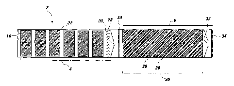
The fire suppression system 2 may include a combustion chamber 4 and an
effluent train 6, as shown in FIGs. 1 and 2. The fire suppression system 2 may
be
formed from a material and construction design having sufficient strength to
withstand
pressures generated by the gas generant 8. The pressures generated in the fire
CA 02545245 2006-05-08
WO 2005/056116 PCT/US2004/040248
-7-
suppression system 2 may range from approximately 100 pounds per square
inch ("psi") (approximately 0.690 Mega Pascals ("MPa")) to approximately 1,000
psi
(approximately 6.90 MPa), such as from approximately 600 psi (approximately
4.14
MPa) to approximately 800 psi (approximately 5.52 Mpa). To withstand these
pressures, an outer surface of the combustion chamber 4 and the effluent train
6 may be
formed from a metal, such as steel. The ignition train may be electrically
activated, as
known in the art. The gas generant 8 and an igniter composition 14 maybe
housed in
the combustion chamber 4. The gas generant 8 may be present in the combustion
chamber 4 as a pellet 16 or the gas generant 8 and the igniter, composition 14
maybe
pelletized, as described in more detail below. Embodiments of the pellet 16
are
illustrated in FIGs. 3a and 3b and are described in more detail below.
The gas generant 8 in the combustion chamber 4 may be ignited to produce the
gaseous combustion products of the inert gas mixture by an ignition train
using sensors
that are configured to detect the presence of the fire in the space. The
sensors may
initiate an electrical impulse in the ignition train. The sensors are
conventional and, as
such, are not discussed in detail herein. The electrical impulse may then
ignite an
initiating device 12, such as a squib, semiconductor bridge, or other
conventional
initiating device. Heat flux from the initiating device 12 may be used to
ignite the
igniter composition 14, which, in turn, ignites the gas generant 8. The
igniter
composition 14 and the gas generant 8 are described in more detail below. When
ignited or combusted, the igniter composition 14 may produce an amount of heat
sufficient to ignite the gas generant 8. Alternatively, the initiating device
12 may be
used to directly ignite the gas generant 8. In one embodiment, the igniter
composition 14 produces solid combustion products, with minimal production of
gaseous combustion products. The combustion products produced by this igniter
composition 14 may include a minimal amount of carbon-containing combustion
products.
In addition to housing the ignition train, the combustion chamber 4 may house
the igniter composition 14 and the gas generant 8. The gas generant 8 may be
formed
into a pellet 16 for use in the fire suppression system 2. Alternatively, the
pellet 16
may include the gas generant 8 and the igniter composition 14, with the
igniter
composition 14 present predominantly on an outer surface of the pellet 16. The
gas
CA 02545245 2006-05-08
WO 2005/056116 PCT/US2004/040248
-8-
generant 8 may be a nonazide gas generant composition that produces gaseous
combustion products and solid combustion products. The gaseous combustion
products may be substantially free of carbon-containing gases or NOR.
Effluents
produced by the combustion of the gas generant 8 maybe substantially free of
NO2 and
may have less than 100 parts per million ("ppm") of other effluents, such as
CO or
NH3. For instance, the gas generant 8 may produce nitrogen and water as its
gaseous
combustion products. At least a portion of the gaseous combustion products
produced
by combustion of the gas generant 8 may form the inert gas mixture. In one
embodiment, substantially all of the gaseous combustion products form the
inert gas
mixture so that a mass of the gas generant 8 used in the pellet 16 may remain
as small
as possible but yet still produce an effective amount of the inert gas mixture
to
extinguish the fire. A catalyst may also be present in the gas generant 8 to
convert
undesirable, toxic gases into less toxic, inert gases that may be used in fire
suppression.
The gaseous combustion products may be generated within a short amount of time
after the gas generant 8 is ignited. For instance, the gas generant 8 may
produce the
gaseous combustion products within approximately 20 seconds to approximately
60 seconds after its ignition so that the inert gas mixture may be dispersed
and the fire
extinguished within approximately 30 seconds to approximately 60 seconds.
During combustion of the gas generant 8, substantially all of the combustion
products that are solid at ambient temperature congeal into a solid mass,
reducing
particulates and smoke formed by combustion of the gas generant. The solid
combustion products may produce a slag, which includes metallic elements,
metal
oxides, or combinations thereof. The slag may fuse on or near a burning
surface of the
pellet 16 when the gas generant 8 is combusted, producing a porous, monolithic
frit.
Since the slag fuses into a porous mass at or near the surface of the pellet
16 as it
combusts, particulates produced during combustion of the pellet 16 may be
minimized,
In one embodiment, the gas generant 8 is a HACN composition, as disclosed in
United States Patent Nos. 5,439,537 and 6,039,820, both to Hinshaw et al. The
HACN
used in the gas generant 8 may be recrystallized and include less than
approximately
0.1 % activated charcoal or carbon. By maintaining a low amount of carbon in
the gas
generant 8, the amount of carbon-containing gases, such as CO, C02, or
mixtures
thereof, may be minimized upon combustion of the gas generant 8.
Alternatively, a
CA 02545245 2006-05-08
WO 2005/056116 PCT/US2004/040248
-9-
technical grade HACN having up to approximately I% activated charcoal or
carbon
maybe used. It is also contemplated that conventional gas generants 8 that
produce
gaseous combustion products that do not include carbon-containing gases or NOx
may
also be used.
The HACN composition, or other gas generants 8, may include additional
ingredients, such as at least one of an oxidizing agent, ignition enhancer,
ballistic
modifier, slag enhancing agent, cooling agent, chemical fire suppressant,
inorganic
binder, or an organic binder. Many additives used in the gas generant 8 may
have
multiple purposes. For sake of example only, an additive used as an oxidizer
may
provide cooling, ballistic modifying, or slag enhancing properties to the gas
generant 8.
The oxidizing agent maybe used to promote oxidation of the activated charcoal
present
in the HACN or of the ammonia groups coordinated to the cobalt in the HACN.
The
oxidizing agent may be an ammonium nitrate, an alkali metal nitrate, an
alkaline earth
nitrate, an ammonium perchlorate, an alkali metal perchlorate, an alkaline
earth
perchlorate, an ammonium peroxide, an alkali metal peroxide, or an alkaline
earth
peroxide. The oxidizing agent may also be a transition metal-based oxidizer,
such as a
copper-based oxidizer, that includes, but is not limited to, basic copper
nitrate
([Cu2(OH)3NO3]) ("BCN"), Cu20, or CuO. In addition to being oxidizers, the
copper-based oxidizer may act as a coolant, a ballistic modifier, or a slag
enhancing
agent. Upon combustion of the gas generant 8, the copper-based oxidizer
mayproduce
copper-containing combustion products, such as copper metal and cuprous oxide,
which are miscible with cobalt combustion products, such as cobalt metal and
cobaltous oxide. These combustion products produce a molten slag, which fuses
at or
near the burning surface of the pellet 16 and prevents particulates from being
formed.
The copper-based oxidizer may also lower the pressure exponent of the gas
generant 8,
decreasing the pressure dependence of the burn rate. Typically, HACN-
containing gas
generants 8 that include copper-based oxidizers ignite more readily and bum
more
rapidly at or near atmospheric pressure. However, due to the lower pressure
dependence, they burn less rapidly at extremely high pressures, such as those
greater
than approximately 3000 psi (greater than approximately 20.68 MPa).
The ignition enhancer may be used to promote ignition of the gas generant 8 at
a low positive pressure, such as from approximately 14 psi (approximately
0.097 MPa)
CA 02545245 2006-05-08
WO 2005/056116 PCT/US2004/040248
-10-
to approximately 500 psi (approximately 3.45 MPa). The ignition enhancer may
be a
conductive material having a large surface area. The ignition enhancer may
include,
but is not limited to, amorphous technical grade boron, high surface area
flaked copper,
or flaked bronze. The ballistic modifier may be used to decrease the bum rate
pressure
exponent of the gas generant. For instance, if the gas generant 8 includes
cupric oxide
and submicron particle size titanium dioxide, the gas generant may have a
pressure
exponent of less than approximately 0.3. Another ballistic modifier that may
be used
in the gas generant 8 is high surface area iron oxide. The ballistic modifier
may also
promote ignition of the gas generant 8. Additives that are able to provide
ballistic
modifying and ignition enhancing properties may include, but are not limited
to, high
surface area transition metal oxides and related species, such as basic copper
nitrate
and flaked metals, such as flaked copper.
The cooling agent may be used to lower the flame temperature of the gaseous
combustion products. Since high flame temperatures contribute to the formation
of
toxic gases, such as NO and CO, cooling the gaseous combustion products is
desirable.
In addition, by using the cooling agent in the gas generant 8, less cooling of
the
gaseous combustion products may be necessary in the effluent train 6. The
cooling
agent may absorb heat due to its intrinsic heat capacity and, potentially,
from an endothermic phase change, such as from a solid to a liquid, or an
endothermic reaction,
such as a decomposition of metal carbonates or metal hydroxides to metal
oxides and
carbon dioxide or water, respectively. Many of the additives previously
described,
such as the oxidizing agent, the ignition enhancer, and the ballistic
modifier, may act as
the cooling agent. For instance, the cooling agent may be a metal oxide, non-
metal
oxide, metal hydroxide, metal carbonate, or a hydrate thereof. However,
desirably the
cooling agent is not a strong oxidizing or reducing agent.
The slag enhancing agent may be used to meld the combustion products of the
gas generant 8 into a cohesive solid, but porous, mass. Upon combustion of the
gas
generant 8, the slag enhancing agent may melt or produce molten combustion
products
that adhere to the solid combustion products and join the solid combustion
products
into the solid mass. Since the solid combustion products are melded together,
the
amount of smoke or particulates produced may be reduced. Silicon dioxide
(SiO2),
titanium oxide, magnesium oxide, or copper-containing compounds may be used as
the
CA 02545245 2006-05-08
WO 2005/056116 PCT/US2004/040248
-11-
slag enhancing agent. Desirably, titanium oxide or magnesium oxide is used
because
they produce low levels of NO,, upon combustion of the gas generant 8. The
concentration of NO, in the gaseous combustion products may also be reduced by
including a catalyst for NO, in the gas generant 8. For sake of example only,
the
catalyst may be tungsten oxide, which converts NOx to nitrogen in the presence
of
ammonia.
The chemical fire suppressant or chemical fire retardant may also be used in
the
gas generant 8. The chemical fire suppressant may be a compound or a mixture
of
compounds that affects flames of the fire, such as a compound that delays
ignition and
reduces the spread of the flames in the space. The chemical fire suppressant
may trap
radicals, such as H, OH, 0, or HO2 radicals, which are important to oxidation
in the
vapor phase. The chemical fire' suppressant may be a halogenated organic
compound,
a halogenated inorganic compound, or mixtures thereof.
The inorganic binder may provide enhanced pellet integrity when the pellet 16
is subjected to mechanical or thermal shock. The inorganic binder may be
soluble in a
solvent that is used to process the gas generant 8, such as water. As the
solvent
evaporates, the inorganic binder may coat solid particles of the gas generant
8, which
enhances crush strength of granules and pellets 16 produced with the gas
generant 8.
In addition, since the binder is inorganic, carbon-containing gases such as CO
or C02,
.20 may not be produced when the gas generant is combusted. The inorganic
binder may
include, but is not limited to, a silicate, a borate, boric acid, or a mixture
thereof. For
instance, sodium silicate, sodium metasilicate (Na2Si03.5H2O), sodium
borosilicate,
magnesium silicate, calcium silicate, aluminosilicate, aluminoborosilicate, or
sodium
borate maybe used as the inorganic binder. In addition, HACN may act as the
inorganic binder.
Small amounts of an organic binder may also be used in the gas generant 8 as
long as minimal amounts of CO or CO2 are produced during combustion. Gas
generants 8 that include even a small amount of organic binder may have
improved
crush strength in pellet form compared to gas generants 8 that are free of
organic
binders. The organic binder may be present in the gas generant 8 from
approximately 0.5% to approximately 2.0%. The organic binder may be a
synthetic or
naturally occurring polymer that dissolves or swells in water including, but
not limited
CA 02545245 2006-05-08
WO 2005/056116 PCT/US2004/040248
-12-
to, guar gum,'polyacrylamide, and copolymers of polyacrylamide and sodium
polyacrylate. The organic binder, .in powder form, may be blended with dry
ingredient(s) prior to the addition of water to promote dispersion of the
organic binder.
A sufficient amount of water may be added during mixing to produce a thick
paste,
which is subsequently dried and granulated prior to pelletization. Organic
binders that
dissolve or swell in organic solvents may also be used, such as ethyl
cellulose, which
dissolves or swells in ethanol. Gas generants 8 that include ethyl cellulose
may be dry
blended prior to mixing in the ethanol. The resulting thick paste may be
subsequently
dried and pressed into pellets 16. Curable polymeric resins may also be used
as
organic binders in the gas generant 8. The curable polymeric resin maybe
blended
with the gas`generant 8 and a curative in the absence of solvent or in the
presence of a
small amount of solvent to promote dispersion of the small amounts of the
curable
polymeric resin and the curative. The resulting powder may be pressed into a
pellet 16
and allowed to cure at elevated temperature, such as at a temperature of
approximately 135 F (approximately 57.2 C). The curable polymeric resin may
include, but is not limited to, epoxy-cured polyesters and hydrosilylation-
cured
vinylsilicones. The organic binder may also include water-soluble, organic
compounds
that have a low carbon content, such as guanidine nitrate. If guanidine
nitrate is used as
the organic binder, it may be present in the gas generant 8 from approximately
1.0% to
approximately 5.0%.
In one embodiment, the gas generant 8 used in the fire suppression system 2
includes recrystallized HACN, cupric oxide (CuO), titanium dioxide (TiO2), and
high
molecular weight polyacrylamide ([CH2CH(CONH2]õ ). In another embodiment, the
gas generant includes recrystallized HACN, CuO, silicon dioxide (SiO2), TiO2,
and
polyacrylamide. In another embodiment, the gas generant includes
recrystallized
HACN, cuprous oxide (Cu2O), and TiO2.
The gas generant 8 may be produced by conventional methods, such as by
using a vertical mixer, a muller mixer, a slurry reactor, or by dry blending
the
ingredients of the composition. In the vertical mixer, the solid ingredients
of the gas
generant 8 may be mixed in a solution that includes HACN dissolved in from
approximately 15% by weight to approximately 45% by weight water. Ignitability
and
ease of combusting the gas generant 8 may increase when high concentrations of
CA 02545245 2006-05-08
WO 2005/056116 PCT/US2004/040248
-13-
HACN are dissolved during the mixing process. The water maybe heated to 165 F
(73.9 C) to increase the solubility of the HACN. Mixing the gas generant 8 at
high
water content (greater than approximately 35% by weight) and warm temperature
(greater than approximately 145 F (greater than approximately 62.8 C))
dissolves at
least a portion of the HACN and coats the additional ingredients. A high shear
mixer,
such as a dispersator, may be used to completely wet the high surface area
solid
ingredients before adding them to the vertical mixer or the high surface area
solid
ingredients may be preblended in a dry state. A powdered binder may be blended
with
the HACN prior to addition of water or another appropriate solvent. The slurry
maybe
dried in a convection oven.
In one embodiment, a muller mixer is used to disperse the curable polymeric
resin and the curative into the powdered ingredients of the gas generant 8. A
small
amount of solvent may also be added to promote dispersal of the curable
polymeric
resin and the curative. The gas generant 8 including the curable polymeric
resin is
allowed to cure once it has been pressed into the pellet 16.
To form the gas generant 8 in the slurry reactor, the HACN may be completely
dissolved in water at a temperature of approximately 180 F (approximately 82.2
C). If
technical grade HACN is used, any activated charcoal in the heated HACN
solution
may be removed, such as by filtration or another process. The heated HACN
solution
may be added to a cool, rapidly mixed suspension of the solid ingredients of
the gas
generant 8. Alternatively, a predispersed slurry of the solid ingredients may
be slowly
added to the rapidly stirred, HACN solution as it cools. Either of these
methods may
promote the formation of HACN crystallites on the insoluble solid ingredients
of the
gas generant 8. Once the suspension is cooled to a temperature ranging from at
least
approximately 80 F (approximately 26.7 C) to approximately 100 F
(approximately
37.8 C), it maybe filtered and the solids dried. The filtrate maybe recycled
as the
liquid phase in subsequent slurry mixes.
To dry blend the gas generant 8, the HACN maybe mixed with the other
ingredients of the gas generant 8 using a v-shell, rotary cone, or Forberg
blender. A
small amount of moisture may be added to the mixture to minimize dusting. The
mixture may then be dried before pelletization.
CA 02545245 2006-05-08
WO 2005/056116 PCT/US2004/040248
-14-
As previously described, the gas generant 8 or the igniter composition 14 and
the gas generant 8 maybe formed into the pellet 16. The pellet 16 maybe formed
by
compressing the gas generant 8 or the igniter composition 14 and the gas
generant 8
together to form a cylindrically-shaped pellet 16, as illustrated in FIG. 3a.
However,
the geometry of the gas generant 8 used in the fire suppression system 2 may
depend
on a desired ballistic performance of the gas generant 8, such as a desired
bum rate or
rate of evolution of the inert gas mixture as a function of time. Burn rates
are typically
categorized as a progressive burn, a regressive burn, or a neutral burn. A
progressive
burn is provided when the burning surface of the pellet 16 increases gradually
as the
pellet 16 burns. In a progressive burn, the rate of evolution of the inert gas
mixture
increases as a function of time. A regressive bum is provided when the burning
surface
of the pellet 16 decreases gradually as the pellet 16 burns. In a regressive
burn, the rate
of evolution of the inert gas mixture is initially high and decreases as a
function of
time. If the burning surface of the pellet 16 burns at a constant rate, a
neutral burn is
provided. In one embodiment, the gas generant 8 is formed into a pellet 16
having a
center-perforated grain geometry, as illustrated in FIG. 3b. The center-
perforated grain
geometry has a high surface area, burns rapidly, and provides a neutral burn.
The
pellet 16 may also be formed into other shapes that provide a neutral burn as
opposed
to a regressive or progressive burn. , The center-perforated pellet 16 may be
produced
using an appropriately designed die or by drilling a hole into a cylindrical
pellet 16,
using appropriate safety precautions.
The pellet 16 may include at least one layer of the igniter composition 14 in
contact with one or more surfaces of the gas generant 8. A configuration of
the igniter
composition 14 used in the fire suppression system 2 may depend on the
geometry of
the gas generant 8. For instance, the pellet 16 may include a layer of the
igniter
composition 14 above a layer of the gas generant 8. Alternatively, a layer of
the igniter
composition 14 may be present below the gas generant 8 or may be present on
multiple
surfaces of the pellet 16. The igniter composition 14 may also be pressed on
the
surface of the pellet 16. Alternatively, the igniter composition 14 may be
powdered,
granulated, or pelletized and housed in a metal foil packet that is placed on
or near the
surface of the pellet 16. The metallic foil packet may include steel wool or
another
conductive material that absorbs heat from the igniter composition 14 and
transfers it to
CA 02545245 2006-05-08
WO 2005/056116 PCT/US2004/040248
-15-
the surface of the gas generant 8. The igniter composition 14 may also be
placed in a
perforated flash tube within the center-perforation of the pellet 16. If the
igniter
composition 14 is granular or powdered, the perforated flash tube maybe lined
internally or externally with a metal foil or the igniter composition 14 maybe
inserted
into the perforated flash tube in preloaded foil packets.
In one embodiment, the igniter composition 14 includes from
approximately 15% to approximately 30% boron and from approximately 70% to
approximately 85% potassium nitrate. This igniter composition 14 is known in
the art
as "B/KNO3" and may be formed by conventional techniques. In another
embodiment,
an igniter composition 14 having strontium nitrate, magnesium, and small
amounts of a
polymeric organic binder, such as nylon, may be used. The igniter composition
14 is
referred to herein as a Mg/Sr(N03)2/binder composition. If the organic binder
is nylon,
the igniter composition 14 is referred to herein as a Mg/Sr(N03)2/nylon
composition.
Since magnesium is water reactive, the organic binder used in the igniter
composition 14 maybe soluble in organic solvents. For instance, ethyl
cellulose or
polyvinylacetate may also be used as the organic binder. The
Mg/Sr(N03)2/binder
composition may be formed by conventional techniques. The igniter composition
14
may also include mixtures of B/KNO3 and Mg/Sr(N03)2/binder. The igniter
compositions disclosed in United States Patent No. 6,086,693 may also be used
as the
igniter composition 14.
The pellet 16 maybe formed by layering the granules of the igniter
composition 14 above or below the layer of the gas generant 8 in a die so that
the
igniter composition 14 and the gas generant 8 are in contact with one another.
A
pressure of approximately 8,000 psi (approximately 55.2 MPa) maybe used to
form
the pellet 16, which has a porosity ranging from approximately 5% to
approximately 20%. The igniter composition 14 and the gas generant 8 may be
compressed into the pellet 16 using a metal sleeve or a metal can, which
provides
support while the pellet 16 is being produced, handled, or stored. The metal
can or the
metal sleeve may also be used to inhibit burning of surfaces of the pellet 16
that are
enclosed by the metal sheathing. In the fire suppression system 2 of the
present
invention, the pellet 16 may burn at a controlled rate so that the amount of
inert gas
mixture produced during the burn remains constant as a function of time. To
achieve a
CA 02545245 2006-05-08
WO 2005/056116 PCT/US2004/040248
-16-
neutral burn, at least one surface of the pellet 16 may be covered or
inhibited by the
metal can or metal sleeve so that these surfaces do not bum. An inner surface
of the
metal sheathing may also be painted with an inert inorganic material, such as
sodium
silicate or a suspension of magnesium oxide in sodium silicate, to inhibit the
surfaces
of the pellet 16.
The pellets 16 may be housed in the combustion chamber 4 and have a total
mass that is sufficient to produce an amount of the inert gas mixture
sufficient for
extinguishing the fire in the space. For sake of example only, in order to
lower the
oxygen concentration and extinguish a fire in a 1,000 cubic foot (28.32 cubic
meter)
space, the gas generant 8 may have a total mass of approximately 40 pounds
(approximately 18 kg). The inert gas mixture produced by the combustion of the
gas
generant 8 may lower the oxygen concentration in the space to a level that
sustains
human life for a limited duration of time. For instance, the oxygen
concentration in the
space may be lowered to approximately 13% by volume for approximately five
minutes
The combustion chamber 4 may be configured to house multiple pellets 16 of
the gas generant 8 or the igniter composition 14 and the gas generant 8.
Therefore, the
fire suppression system 2 of the present invention may be easily configured
for use in
spaces of various sizes. For instance, the fire suppression system 2 may
include one
pellet 16 if the fire suppression system 2 is to be used in a small space.
However, if the
fire suppression system 2 is to be used in a larger space, the combustion
chamber 4
may include two or more pellets 16 so that the sufficient amount of the inert
gas
mixture maybe produced. For sake of example only, in a 500 cubic foot (14.16
cubic
meter) space, four pellets 16 having a 5.8-inch (14.73 cm) outer diameter, a
2.6-inch
(6.6 cm) height, and a weight of 4.44 pounds (2.01 kg) may be used, while
eight of
these pellets 16 may be used in a 1,000 cubic foot (28.32 cubic meter) space.
In a
2,000 cubic foot (55.63 cubic meter) space, two generators, each containing
eight
pellets 16, maybe strategically positioned. The pellets 16 may have an
effective
burning surface area so that the inert gas mixture may be produced within a
short time
period after initiation of the gas generant 8. For instance, the inert gas
mixture may be
produced with approximately 20 seconds to approximately 60 seconds after
initiation
of the gas generant 8. If the fire suppression system 2 includes multiple
pellets 16, the
CA 02545245 2006-05-08
WO 2005/056116 PCT/US2004/040248
-17-
pellets 16 maybe ignited so that they are combusted simultaneously to provide
a
sufficient amount of the inert gas mixture to extinguish the fire.
Alternatively, the
pellets 16 may be ignited sequentially so that the inert gas mixture is
produced at
staggered intervals.
In one embodiment, the ignition train includes a squib, which, when
electrically
activated, ignites a granular or pelletized composition of B/KNO3 in an
ignition
chamber. The hot effluents produced by combustion of the B/KNO3 composition
pass
into the combustion chamber 4 and ignite the secondary ignition or igniter
composition 14, which maybe located in the metallic foil packet, pressed or
painted on
the surface of the pellet 16, or placed in the perforated flash tube
positioned in the
center-perforation of the pellet 16.
The fire suppression system 2 may be designed in various configurations
depending on the size of the space in which the fire is to be extinguished.
Exemplary
configurations of the fire suppression system 2 include, but are not limited
to, those
illustrated in FIGs. 1 and 4. As illustrated in FIG. 4, the fire suppression
system 2 may
have a tower configuration having a plurality of gas generators 70. A group or
cluster
of the gas generators 70 may be utilized to generate a sufficient amount of
the inert gas
mixture, which is delivered to the space in which the fire is to be
suppressed. The
number of gas generators 70 in the cluster and a controllable sequence in
which the gas
generators 70 are initiated allows the ballistic performance of the fire
suppression
system 2 to be tailored to provide a sufficient amount of the inert gas
mixture to the
space. The number of gas generators 70 may also be adjusted to provide a
desired
mass flow rate history and action time of the inert gas mixture to the space.
To
configure the fire suppression system 2 for a particular space, gas generators
70 may be
added to or removed from the tower cluster. The fire sequencing used to
initiate the
gas generator 70 may be accomplished by controlling the timing of the
electrical
impulse to the initiating device 12 or by utilizing a pyrotechnic fuse. A
column length
of the pyrotechnic fuse maybe selected to determine the time of initiation of
the gas
generator 70. The gas generator 70 may house the gas generant 8, which is
illustrated
in FIG. 4 as having a center-perforated grain geometry. However, the gas
generator 70
may accommodate other geometries of the gas generant 8 depending on the
desired
ballistic performance of the gas generant 8. The geometry of the igniter
CA 02545245 2006-05-08
WO 2005/056116 PCT/US2004/040248
-18-
composition 14 used in the fire suppression system 2 may depend on the grain
geometry of the gas generant 8. For instance, the igniter composition 14 maybe
loaded into the metallic foil packets and placed on the surfaces of the gas
generant 8.
Alternatively, the igniter composition 14 may be placed in the perforated
flash tube
(not shown), which extends down the length of a center-perforated pellet 16 of
the gas
generant 8.
As previously described, the igniter composition 14 is ignited, which in turn
combusts the gas generant 8 and produces the gaseous combustion products. The
gaseous combustion products form the inert gas mixture, which then passes
through a
filter 18 and a controlling orifice 20 into a diffuser chamber 72. The filter
18 may be a
screen mesh, a series of screen meshes, or a conventional filter device that
removes
particulates from the inert gas mixture. The filter 18 may also provide
cooling of the
inert gas mixture. The controlling orifice 20 may control the mass flow out of
the gas
generator 70 and, therefore, may control the flow rate of the inert gas
mixture and the
pressure within the gas generator 70. In other words, the controlling orifice
20 maybe
used to maintain a desired combustion pressure in the fire suppression system
2. The
pressure in the gas generator 70 may be maintained at a level sufficient to
promote
ignition and to increase the burn rate of the gas generant S. The pressure may
also
promote the reaction of reduced toxic gases, such as CO and NH3, with gases
that are
oxidized, such as NOR, which significantly reduces the concentration of these
gases in
the effluent gases. The controlling orifice 20 may be of a sufficient size to
produce a
combustion pressure ranging from approximately 600 psi (approximately 4.14
MPa) to
approximately 800 psi (approximately 5.52 MPa) in the gas generator 70.
Therefore,
walls 22 of the gas generator 70 and of other portions of the fire suppression
system 2
may be formed from a material that is capable of withstanding the maximum
working
pressure at the operating temperatures with appropriate engineering safety
factors. In
this tower configuration, high pressures are restricted to the small diameter,
gas
generator 70 volumes, while the remainder of the fire suppression system 2
operates at
low pressures, which results in cost and weight savings.
In the diffuser chamber 72, plumes of the high velocity, inert gas mixture
impinge on a flow deflector 74. The flow deflector 74 recirculates the inert
gas
mixture and results in a more uniform flow through a perforated diffuser plate
or first
CA 02545245 2006-05-08
WO 2005/056116 PCT/US2004/040248
-19-
diffuser plate 24. The first diffuser plate 24 may disperse the inert gas
mixture so that
it does not exit the gas generator 70 as a high velocity jet. The inert gas
mixture then
passes through a heat management system 26 that includes cooling media or
effluent
scavenging media. The heat management system 26 may reduce the temperature of
the
inert gas mixture to a temperature that is appropriate to suppress the fire.
Since
combustion of the gas generant 8 produces a significant amount of heat in the
gas
generator 70, the inert gas mixture maybe cooled before it is introduced into
the space.
For sake of example only, the heat released from a gas generant 8 combusted in
a
2,000 cubic foot (56.63 cubic meter) space may be approximately 40,000 British
Thermal Units ("BTU") (approximately 42,200,000 joules). In one embodiment,
the
heat management system 26 is a heat sink. The heat sink may be formed from
conventional materials that are shaped into beds, beads, or tube clusters. The
materials
used in the heat sink may include, but are not limited to, metal, graphite, or
ceramics.
The material used in the heat sink and the geometry of the heat sink may be
selected by
one of ordinary skill in the art so that the heat sink provides the
appropriate heat
transfer surface, thermal conductivity, heat capacity, and thermal mass.
In another embodiment, the heat management system 26 includes a phase
change material ("PCM"). The PCM removes thermal energy from the inert gas
mixture by utilizing the PCM's latent heat of fusion and stores the thermal
energy. The
PCM may be an inert material that does not react with the inert gas mixture
including,
but not limited to, a carbonate, phosphate, or nitrate salt. For instance, the
PCM may
be lithium nitrate, sodium nitrate, potassium nitrate, or mixtures thereof.
The PCM is
described in more detail below.
The cooled, inert gas mixture may then be dispersed into the space through at
least one final orifice 32, which reduces the pressure of the inert gas
mixture relative to
the pressure in the gas generator 70. The geometry of the final orifice(s) 32
may be
selected based on the geometry of the space and the placement of the fire
suppression
system 2 in the space. Since the inert gas mixture is generated
pyrotechnically, high
pressure gas storage tanks and accompanying hardware to disperse the inert gas
mixture may not be needed in the fire suppression system 2 of the present
invention.
Another configuration of the fire suppression system 2 is shown in FIG. 1. The
inert gas mixture, including nitrogen and water vapor, may be passed through
the
CA 02545245 2006-05-08
WO 2005/056116 PCT/US2004/040248
-20-
filter 18 to remove any particulates that are produced upon combustion of the
gas
generant 8. The inert gas mixture may then be flowed through the controlling
orifice 20 located at the exit of the combustion chamber 4. The controlling
orifice 20
may control the mass flow out of the combustion chamber 4 and, therefore, may
control the pressure within the combustion chamber 4. In other words, the
controlling
orifice 20 may be used to maintain a desired combustion pressure in the fire
suppression system 2. The controlling orifice 20 may be of a sufficient size
to produce
a combustion pressure ranging from approximately 400 psi (approximately 2.76
MPa)
to approximately 600 psi (approximately 4.14 Mpa) in the combustion chamber 4.
Therefore, walls 22 of the combustion chamber 4 and of the effluent train 6
may be
formed from a material capable of withstanding the maximum working pressure at
the
operating temperatures with appropriate engineering safety factors.
The combustion chamber 4 may also include the first diffuser plate 24 that
disperses or diffuses the inert gas mixture into the heat management system 26
of the
effluent train 6. The first diffuser plate 24 may disperse the inert gas
mixture so that it
does not exit the combustion chamber 4 as a high velocity jet. Rather, a
laminar flow
of the inert gas mixture may enter the effluent train 6. The effluent train 6
may include
the heat management system 26 or a gas coolant material to reduce the
temperature of
the inert gas mixture to a temperature appropriate to suppress the fire. In
one
embodiment, the heat management system 26 is a heat sink, as previously
described.
In another embodiment, the heat management system 26 includes PCM 28. As
previously described, the PCM 28 removes thermal energy from the inert gas
mixture
by utilizing the PCM's latent heat of fusion and stores the thermal energy.
The
PCM 28 maybe an inert material that does not react with the inert gas mixture
including, but not limited to, a carbonate, phosphate, or nitrate salt. For
instance, the
PCM 28 maybe lithium nitrate, sodium nitrate, potassium nitrate, or mixtures
thereof.
The PCM 28 used in the heat management system 26 may be selected by one of
ordinary skill in the art based on its phase change temperature, latent heat
of fusion, or
thermal properties, such as thermal conductivity, burn rate, heat capacity,
density, or
transition or melting temperature. In addition to these properties, the
material selected
as the PCM 28 may be dependent on the amount of time that is needed to ignite
the gas
generant 8 and produce the gaseous combustion products of the inert gas
mixture. To
CA 02545245 2006-05-08
WO 2005/056116 PCT/US2004/040248
-21-
transfer heat from the inert gas mixture to the PCM 28, a tube cluster 30 may
be
embedded in, or surrounded by, the PCM 28. The tube cluster 30 maybe formed
from
metal tubes that are capable of conducting heat, such as steel or copper
tubes. The
length, inner diameter, and outer diameter of the metal tubes may be selected
by one of
ordinary skill in the art depending on the amount of time required for the
heat produced
by the gas generant 8 to be conducted from the inert gas mixture to the PCM
28. The
geometry of the tube cluster 30 in relation to the PCM 28 maybe selected by
one of
ordinary skill in the art based on the amount of time necessary to ignite the
gas
generant 8 and produce gaseous combustion products and the amount of heat
produced
by the gas generant 8. When the inert gas mixture is flowed from the
combustion
chamber 4 and through the tube cluster 30, heat flux from the inert gas
mixture maybe
transferred through the tube cluster 30 and into the PCM 28. When the PCM 28
is
heated to its phase change temperature, it may begin to absorb its latent heat
of fusion.
Once the PCM 28 has absorbed its latent heat of fusion, an interface boundary
temperature differential of the PCM 28 remains constant, which may enhance
heat
conduction from the surface of the tube cluster 30 to the PCM. Thermal energy
may be
stored in the PCM 28 based on the heat capacity of its liquid state once the
PCM 28 has
absorbed its latent heat of fusion.
The heat management system 26 may also be doped with a selective catalytic
reduction ("SCR") catalyst or a non-selective catalytic reduction ("NSCR")
catalyst to
convert any undesirable gases that are produced as gaseous combustion products
into
gases that maybe used in the inert gas mixture. For instance, the SCR and NSCR
catalysts may be used to convert ammonia or nitrogen oxides into nitrogen and
water,
which may then be used in the inert gas mixture.
After the inert gas mixture has passed through the heat management system 26,
the inert gas mixture may pass through a final orifice 32, which reduces the
pressure of
the inert gas mixture relative to the pressure in the combustion chamber 4.
The inert
gas mixture may then pass through a second diffuser plate 34 to uniformly
disperse the
inert gas mixture throughout the space. Since the inert gas mixture is
generated
pyrotechnically, high pressure gas storage tanks and accompanying hardware to
disperse the inert gas mixture may not be needed in the fire suppression
system 2 of the
present invention.
CA 02545245 2006-05-08
WO 2005/056116 PCT/US2004/040248
-22-
The following are examples of gas generant compositions and igniter
compositions for use within the scope of the present invention. These examples
are
merely illustrative and are not meant to limit the scope of the present
invention in any
way.
Examples
Example 1
A HACN Gas Generant Produced Using a Slurry Reactor
A gas generant including HACN, BCN, and Fe203 was produced in the slurry
reactor. A 10 liter baffled slurry tank was filled with 4,900 grams of
distilled water and
stirred with a three blade stationary impeller at 600 revolutions per minute
("rpm"). A
glycol heating bath was used to heat the water to 180 F (82.2 C). After the
water
temperature reached 180 F (82.2 C), 586.1 g of technical grade HACN was added
to
the mixer and stirred at 600 rpm for 10 minutes to allow the HACN to dissolve.
111.64 g of BCN and 18.56 g of Fe203 were dry blended together in a NalgeneTM
quart
container. 100 g of distilled water were then added into the blended BCN/
Fe203 and
stirred'for 5 minutes until an even suspension was made. 58 g of this
suspension of
BCN/ Fe203/water was then injected slowly into the mix bowl with a 30 cc
syringe
while mixing rapidly. The slow addition of solid into the mix bowl allows for
better
oxidizer distribution in the mix. The heating system of the mix bowl was then
turned
off and the system was cooled at 1.4 F/minute (0.78 C/minute) by melting ice
on the
exterior of the mix bowl. When the mix temperature reached 160 F (71.1 C), a
second
addition of 58 g of BCN/ Fe203/water was injected slowly into the mix bowl
with a
cc syringe while mixing rapidly. Cooling with ice was continued after this
addition.
25 When the temperature reached 139.7 F (59.83 C), a third addition of 58 g of
BCN/
Fe203/water was then injected slowly into the mix bowl with a 30 cc syringe
while
mixing rapidly. Cooling with ice was continued after this addition. When the
temperature reached 119.9 F (48.83 C), 56.2 g (the remainder of the
suspension) of
BCN/ Fe203/water was injected slowly into the mix bowl with a 30 cc syringe
while
30 mixing rapidly. Cooling with ice was continued after this addition until
the
temperature reached 75.4 F (24.1 C). At that time, the impellar was stopped
and the
material was transferred out of the mix bowl and into a five gallon bucket.
The mix
CA 02545245 2006-05-08
WO 2005/056116 PCT/US2004/040248
-23-
was then filtered in a vacuum Erlenmeyer flask with a 1-gm paper filter. The
mixed
gas generant was then placed onto a glass tray and dried at 165 F (73.9 C)
overnight to
remove any moisture.
Example 2
A HACN Gas Generant Produced By Vertical Mixing
A five gallon Baker Perkins vertical mixer was filled with 10,857 g of
distilled
water and stirred at 482 rpm. The mix bowl was heated to 165 F (73.9 C). After
the
water temperature reached 165 F (73.9 C), 3,160.0 g of recrystallized HACN was
added into the mixer and stirred slowly at 482 rpm for 15 minutes to allow the
HACN
to partially dissolve and break up any clumps. 1,800 g of Cu2O and 720 g of
TiO2 were
then dry blended by sealing a five gallon bucket and shaking it. The mixer was
stopped and the walls and blades were scraped down to incorporate any material
that
may have migrated up the mix blades. Then, the blend of Cu2O and TiO2 was
added to
the mix bowl and mixed for 15 minutes at 482 rpm. The mixer was stopped and
the
walls and blades were scraped down to incorporate any material that may have
migrated up the mix blades. Then, 3,160 g of recrystallized HACN was added
into the
mix bowl and mixed for 15 minutes at 482 rpm. The mixer was stopped and the
walls
and blades were scraped down. The mixture was mixed for 30 minutes at 1,760
rpm.
The mixer was stopped and the walls and blades were scraped. Then, the mixture
was
mixed for 30 minutes at 1,760 rpm. The mixture was loaded onto velo-stat lined
trays
and dried at 165 F (73.9 C). After drying, the coarse, granular material was
granulated
to a consistent small granule size using a Stokes granulator.
Example 3
A HACN Gas Generant with Organic Binder Produced By Vertical Mixing
To a one gallon Baker Perkins vertical mixer, 2,730 g of recrystallized HACN
and 35 g of granular Cytec Cyanamer N-300 polyacrylamide were added. The two
solids were blended for two minutes, after which 1,750 g of deionized water
was
added. The resulting slurry was mixed for 15 minutes. The mixer was stopped
and the
walls and blades were scraped down to incorporate any material that may have
migrated up the mix blades.
CA 02545245 2006-05-08
WO 2005/056116 PCT/US2004/040248
-24-
In a two-gallon plastic container with a snap-on lid, 630 g of American Chemet
Corp. UP1360OFM cupric oxide and 105 g of DeGussa P-25 titanium dioxide were
preblended by vigorous shaking. Then, the blend of cupric oxide and titanium
dioxide
was added into the mix bowl and mixed for 5 minutes. The mixer was stopped and
the
walls and blades were scraped down to incorporate any material that may have
migrated up the mix blades. The resulting paste was then mixed for an
additional
minutes. The mixture was loaded into glass baking dishes and dried at 165 F
(73.9 C) with occasional stirring. After drying, the coarse granular material
was
granulated to -12 mesh using a Stokes granulator.
Example 4
A HACN Gas Generant Produced in a Rotating Double-Cone Dryer
To a two cubic foot (0.057 cubic meter) rotating double-cone dryer, 2,996 g of
cupric oxide and 817 g of titanium dioxide were added. The material was
blended for
20 minutes by way of rotation of the rotating double-cone dryer. Afterwards,
the inside
walls of the rotating double-cone dryer were scraped down to free any
unblended
material. Next, 23,426 g of recrystallized HACN was added to the rotating
double-cone dryer. The material was blended for an additional thirty minutes
and then
collected.
Example 5
A HACN Gas Generant Containing an Organic Binder Produced in a Muller Mixer
A polymer preblend was prepared by mixing 82 g of Crompton Corp. Fomrez
F17-80 polyester resin with 17.4 g of Vantico Inc. Araldite MY0510
multifunctional
epoxy resin and 0.6 g of powdered magnesium carbonate. To a 12" (30.5 cm)
diameter
muller mixer, 10 g of the polymer preblend and 1,636 g of recrystallized HACN
were
added. This was blended for 10 minutes and the mixing surfaces were scraped
down.
Then, 294 g of American Chemet Corp. UP 13600FM cupric oxide and 60 g of
DeGussa P-25 titanium dioxide were added and the composition was mixed for
5 minutes. The mixer was again scraped down and the composition was blended
for
another 10 minutes. The composition was placed in a freezer and allowed to
warm to
room temperature immediately before pressing it into a pellet.
CA 02545245 2006-05-08
WO 2005/056116 PCT/US2004/040248
-25-
Example 6
Test Article Pellet Pressing
Pellets formed from the gas generants described in Examples 1, 2, or 4 were
produced. To press the pellets, a 1.13 inch (2.87 cm) die assembly was used. A
mold
release agent, polytetrafluoroethylene ("PTFE"), was liberally applied to the
die anvil
and foot to minimize material sticking during the press cycle. 1.5 g of an
igniter
composition having a mixture of 60% B/KNO3 and 40% Mg/Sr(NO3)2/binder was
added to the die and leveled off with a spatula. The igniter composition was
produced
by blending together granules of the B/KNO3 and Mg/Sr(N03)2/binder. 10 g of
the gas
generant described in Examples 1, 2, or 4 was added to the die. The press foot
was
inserted into the top of the die assembly and twisted to ensure proper
alignment. The
pellet was pressed for 60 seconds at 8,000 lbf (35,590 N) and 8,000 psi (55.16
MPa).
After pressing, the anvil was removed from the assembly and the pellet was
pressed out
of the die into a padded cup to minimize damage.
Example 7
Sleeved Test Article Pellet Pressing
Sleeved pellets formed from the gas generants described in Examples 1, 2, or 4
were produced. The press anvil and foot of the die were liberally sprayed with
PTFE.
A 1.05 inch (2.67 cm) internal diameter ("ID") steel ring was placed on the
press anvil.
1.2 g of an igniter composition having a mixture of 60% B/KNO3 and 40%
Mg/Sr(N03)2/binder was then added inside the steel ring. The surface of the
igniter
composition was then leveled with a spatula to ensure an even layer of the
igniter
composition on one surface of the pellet. An alignment sleeve was placed on
top of the
steel sleeve and 14.5 g of the gas generant described in Examples 1 or 2 was
poured
inside the alignment tool. A 1.00 inch (2.54 cm) outer diameter ("OD") press
foot was
inserted into the die. The sleeved pellet was pressed for 60 seconds at 6,900
lbf (30,690
N) and 8,000 psi (55.16 MPa). After pressing, the top surface of the sleeved
pellet
matched the top layer of the steel ring. Therefore, no post pressing process
was
required to remove the pellet from the press die. Instead, the anvil and
alignment piece
pulled off easily, leaving a filled steel ring of the gas generant.
CA 02545245 2006-05-08
WO 2005/056116 PCT/US2004/040248
-26-
Example 8
Sleeved Test Article Pellet Pressing with Hot Wire
Sleeved pellets were also pressed with embedded hot wires by running a loop
of tungsten wire having a 0.010 inch (0.0254 cin) OD through two holes on the
press
anvil. The wire leads were rolled up and stored in the labeled opening on the
underside
of the press anvil. After installing the hot wire in the pressing fixture, the
procedure for
sleeved pellets (described in Example 7) was followed.
Example 9
5.8 Inch (14.7 cm) Diameter Test Pellets
3.3 pound (1.5 kg) pellets were pressed using a 150-ton (136,000 kg) hydraulic
press. The anvil and press foot were sprayed liberally with PTFE. The anvil
was then
inserted into the die walls. 39.6 g of the igniter composition (40% B/KNO3 and
60%
Mg/Sr(N03)2/binder) was added to the die by slowly pouring the material in a
circular
coil pattern starting at the center of the anvil and moving outward toward the
die wall.
The igniter composition was then leveled on top of the press anvil with a
spatula. After
ensuring an even layer of the igniter composition, 1,500 g of the gas generant
described
in Examples 1, 2, or 4 was added to, the die. The press foot was then
carefully inserted
into the die. To ensure proper alignment, the press foot was spun around to
ensure that
no gas generant was trapped between the die walls and press foot. After
alignment, the
pellet was pressed at 211,000 lbf (939,000 N) and 8,000 psi (55.16 MPa) for
60 seconds. To remove the pellet, the press anvil was removed and the die
walls were
positioned on top of a 6.0 inch (15.2 cm) inner diameter ("ID") knockout cup.
A slight
amount of force was applied to the press foot to push the pellet out of the
5.8 inch (14.7
cm) die walls.
Example 10
Test Pellets Pressed in a Steel Can
The gas generant (737 g) described in Example 4 was added to a carbon steel
can having an OD of 6.0 inches (15.2 cm), an ID of 5.8 inches (14.7 cm), a
height of
2.15 inches (5.46 cm), and a depth of 2.06 inches (5.23 cm) and pressed using
a
CA 02545245 2006-05-08
WO 2005/056116 PCT/US2004/040248
-27-
150-ton (136,000 kg) hydraulic press to a maximum pressure of 8,042 psi (55.45
MPa).
Pressure was maintained at or above 8,000 psi (55.16 MPa) for one minute. A
second
addition of 740 g of the gas generant was added to the press die along with a
59.4 g
blend of an igniter composition that included 11 % B/KNO3 and 89%
Mg/Sr(N03)2/binder. The igniter composition was spread evenly on the top
surface of
the gas generant. The remaining gas generant and the igniter composition were
then
pressed at 8,197 psi (56.52 MPa) for one minute. The total height of the gas
generant
and igniter composition after the final press cycle was 2.01 inches (5.11 cm).
Example 11
Subscale Fire Suppression System
A subscale system of the fire suppression system 2 was produced, as shown in
FIG. 2. The gas generant 8 used in the subscale system included a composition
of
HACN, Cu2O, and TiO2, which was prepared as previously described. The igniter
composition 14 included 1 g of 60% B/KNO3 and 40% Mg/Sr(N03)2/binder. The
subscale system included an igniter cover 36, an inner case 40, an outer case
42, a
base 44, a perforated tube 46, a screen retainer 48, a cover fabrication 50,
an inner
barrier 52, a tie rod 54, a perforated baffle 56, a boss 58, and a baffle 60.
An
inhibitor 62, formed from Krylon/Tape, was applied to the bottom of the gas
generant
.20 pellet 16, which came in contact with a spacer 64 in the combustion
chamber 4; In
addition to providing heat management properties, the perforated tube 46
prevents the
escape of particulates from the ignition chamber.
The mass of the gas generant 8 in the fire suppression system 2 was selected
so
that when the inert gas mixture was vented into a 100 cubic foot (2.83 cubic
meter)
enclosure, atmospheric oxygen was displaced and removed to a level low enough
to
extinguish combustion in the enclosure. A 3.3 lb (1.5 kg) pellet having the
gas
generant 8 was used in the subscale system. Upon combustion of the pellet, the
oxygen
content in the 100 cubic foot (2.83 cubic meter) enclosure was reduced to
below
approximately 13% oxygen, as shown in FIG. 5.
In test A, a cylindrical pellet 16 was tested. The pressure generated in the
combustion chamber 4 and the temperature of the gas in the aft of the
combustion
chamber 4 were measured. As shown in FIG. 6, the maximum pressure in the fire
CA 02545245 2006-05-08
WO 2005/056116 PCT/US2004/040248
-28-
suppression system 2 was slightly more than 300 psi (2.07 MPa) at
approximately
9 seconds after ignition of the gas generant 8. The maximum temperature in the
fire
suppression system 2 was less than 500 F (260 C) at approximately 9 seconds
after
ignition of the gas generant 8.
In test B, a cylindrical pellet that was pressed into a metal cylinder and
inhibited on one end was tested. As shown in FIG. 7, the maximum pressure in
the fire
suppression system 2 was approximately 650 psi (approximately 4.48 MPa) at
approximately 18 seconds after ignition of the gas generant 8. The maximum
temperature in the fire suppression system 2 was less than approximately 550 F
(less
than approximately 288 C) at approximately 19 seconds after ignition of the
gas
generant 8.
Example 12
Mini-Generator Test
A mini-generator developed for use in airbag research was used to test pellets
of the igniter composition 14 and gas generant 8 described in Examples 6 or 7.
The
mini-generator is a conventional device that consists of reuseable hardware
and is a
simplified prototype of a driver-side airbag inflator.
Pellets 16 having a mass of from approximately 20 g to approximately 25 g
were ignited in the mini-generator. The gaseous combustion products (or
effluent
gases) of the pellets 16 were transferred into gas-impermeable bags and tested
to
determine the contents of the gaseous combustion products. The gaseous
combustion
products were tested using a conventional, colorimetric assay, i.e., the
Draeger Tube
System, which is known in the art. In the mini-generator, CO levels decreased
from
2,000 parts per million ("ppm") to 50 ppm. NO, levels decreased from 2,000 ppm
to
150 ppm. In addition, a tough, unitary slag was produced.
Example 13
100 Cubic Foot (2.83 Cubic Meter) Tank Test
The pellets 16 described in Example 10 were tested in the subscale fire
suppression system described in Example 11, which was attached vertically to
an
assembly plate near the bottom of a 100 cubic foot (2.83 cubic meter) test
tank
CA 02545245 2006-05-08
WO 2005/056116 PCT/US2004/040248
-29-
equipped with pressure transducers, thermocouples, a video camera, and an
oxygen
sensor. The tank was designed with a vent to eliminate significant
overpressure. A
Thiokol ESO13 squib was electronically activated and the hot effluents
produced by the
squib ignited 6 grams of B/KNO3 in the ignition chamber, which in turn ignited
the
igniter composition 14 that was pressed onto the top surface of the gas
generant 8. The
igniter composition 14 then ignited the gas generant 8. The pressure in the
combustion
chamber reached a maximum pressure of 650 psi (4.48 MPa) in about 18 seconds.
The
pressure in the combustion chamber decreased to 50 psi (0.35 MPa) 25 seconds
after
ignition. Maximum pressure in the 100 cubic foot (2.83 cubic meter) tank was
0.024 psig (166 Pa). After the test, ammonia, carbon monoxide, NOR, and
nitrogen
dioxide were measured using appropriate Draeger tubes at 48 ppm, 170 ppm, 105
ppm
and 9 ppm, respectively.
Example 14
Use of Igniter Composition Placed on the Surface of the Gas Generant Grain
A pellet 16 was pressed into a can similarly to that described in Example 10,
except that the igniter composition was not pressed onto the top surface of
the gas
generant 8. When the resulting pellet 16 was tested in the subscale fire
suppression
system described in Example 11, the Thiokol ESO13 squib ignited 1 g of B/KNO3
in
the ignition chamber which, in turn, ignited a 59.4 g blend of the igniter
composition
(11 % B/KNO3 and 89% Mg/Sr(N03)2/binder) assembled in an aluminum foil packet
placed on the top surface of the gas generant 8. Ignition was enhanced over
that
obtained in Example 13 because the maximum pressure of 900 psi (6.21 MPa) in
the
combustion chamber was reached at 16 seconds after ignition.
Example 15
Use of Flaked Copper-Containing Metals as an Ignition Aid
Two 10 g, 1.1-OD cylindrical pellets 16 were pressed at 8,000 psi (55.16 MPa).
One pellet 16 included the gas generant 8 described in Example 4. The other
pellet 16
included 90% by weight of the gas generant 8 described in Example 4 blended
with 10% by weight of Warner-Bronz finely-divided bronze flakes, produced by
Warner Electric Co., Inc. On the top surface of each pellet 16, 0.5 g of
granular
CA 02545245 2006-05-08
WO 2005/056116 PCT/US2004/040248
-30-
Mg/Sr(NO3)2/binder was present. The igniter composition 14 on each pellet 16
was
ignited by a hot wire. The pellet 16 that included the finely divided bronze
flakes
ignited more smoothly, combusted more rapidly, and produced a stiffer slag
once
combusted compared to the pellet 16 without the finely divided bronze flakes.
Example 16
Evaluation of Binders in HACN Gas Generants (Small Scale)
HACN gas generant compositions were mixed similarly to those described in
Examples 2, 3, 4, and 5. For each composition, three 0.5 inch (1.27 cm)
diameter,
4.0 g pellets were pressed at 2,000 lbs force (8,900 N) for 20 seconds. In
addition,
three 1.1 inch (2.79 cm) diameter, 15.0 g pellets were pressed at 10,000 lbs
force
(44,500 N) for 20 seconds. The pellets were analyzed for crush strength at a
0.125 in/min (0.318 cm/min) compression rate. The 0.5 inch (1.27 cm) pellets
were
used to determine axial crush strength and the 1.1 inch (2.79 cm) diameter
pellets were
analyzed for radial crush strength. The data are summarized in Table 1 and
show that
pellets 16 having the organic binder or inorganic binder had improved axial
crush
strength compared to those compositions having no binder. In addition, many of
the
pellets 16 had improved radial crush strength compared to those compositions
having
no binder.
Table 1: Crush Strength of HACN Gas Generantsa as a Function of Binder.
Mix Pellet Axial Crush Radial Crush
Binder HACN CuO Method Density Strength Strength
(Ex. #) (g/cc) (lbs/kg) (lbs/kg)
None 86.0 11.0 4 1.751 319/145 65/30
None 86.0 11.0 2 1.753 296/134 123/55.8
0.5% cured 81.8 14.7 5 1.841 417/189 121/54.9
polyester
1.0% cured 77.7 18.3 5 1.900 610/277 182/82.6
polyester
2.0% cured 69.3 25.7 5 2.020 795/361 253/115
polyester
3.0% cured 61.0 33.0 5 2.17 1059/480 365/166
polyester
CA 02545245 2006-05-08
WO 2005/056116 PCT/US2004/040248
-31-
Mix Pellet Axial Crush Radial Crush
Binder HACN CuO Method Density Strength Strength
(Ex. #) (g/ce) (lbs/kg) (lbs/kg)
2.0% guar 74.5 20.5 5 1.812 757/343 178/80.7
1.0% poly- 78.0 18.0 4 1.751 507/230 220/99.8
acrylamide
1.5% poly 74.1 21.4 4 1.789 574/260 210/95.3
acrylamide
2.0% poly- 70.1 24.3 4 1.819 586/266 245.7/111.5
acrylamide
1.5% b 78.0 17.5 4 1.792 672/305 232/105
copolymer
4.0%
guanidine 79.2 13.8 4 1.762 373/169 149/67.6
nitrate
1.0% ethyl 77.0 19.0 4 1.836 609/276 181/82.1
cellulose
1.5% cured 71.4 23.8 5 1.949 336/152 46/20.9
silicone
2.5% sodium 84.1 10.4 4 1.725 403/183 217/98.4
silicate
a All formulations include 3% titanium dioxide.
b The copolymer includes 90% sodium acrylate and 10% acrylamide monomers,
respectively.
Gas-generator hardware larger in scale than that used in Example 17 was used
to test 1.42 inch (3.61 cm) diameter pellets 16 of formulations selected from
Table 1.
The 1.42 inch (3.61 cm) diameter pellets were produced by pressing 58.0 g of
the gas
generant at 16,000 lbs force (71, 200 N) for 60 seconds. Behind a protective
shield, a
hole was drilled into the center of each of the pellets 16 using a 0.3015 inch
(0.7658
cm) OD drill bit to produce a center-perforation in the pellets. The gas
generator
hardware was attached to a 60-liter tank. The pellets were then ignited and
combustion
analyses were performed on the gaseous combustion products. After combustion,
dilution of the air in the 60-liter tank by combustion gases produced by the
gas
generant 8 was sufficient to decrease oxygen content in the tank to
approximately 13%.
Results of these combustion analyses are summarized in Table 2.
CA 02545245 2006-05-08
WO 2005/056116 PCT/US2004/040248
-32-
Table 2: Combustion Analysis of Small Center-Perforated Gas Generant Pellets
T Pellet Maximum Rise CO NO2
Binder In f 1 (g/cc) Density Pressure Time (p lp n) (ppmX) (ppm) (ppm)
(psi/MPa) (sec)
dry blended, l a 1.664 690.4/4.760 1.10 7 55 230 17
no binder
dry blended, . 2a 1.728 688.5/4.747 2.16 86 85 12
no binder
wet mixed,
la 1.668 584.0/4.027 1.28 85 80 220 17
no binder
1% la 1.764 402.3/2.774 2.21 5 105 850 60
polyacrylamide
1% 2a 1.762 528.3/3.643 1.00 83 90 850 28
polyacrylamide
2% guar lb 1.674 637.7/4.397 0.92 170 55 1900 2
1% cured la 1.875 800.8/5.521 1.50 40 85 680 60
polyester
I% ethyl la 1.829 390.6/2.693 1.97 10 150 1200 85
cellulose
1% copolymerz la 1.769 254.9/1.758 3.76 23 300 1200 150
4% guanidine 2a 1.737 752.9/5.191 1.05 58 70 1700 12
nitrate
2.5% sodium 2b 1.706 1299.8/8.962 11.63 340 125 380 40
silicate
1.5% silicone 2a 1.945 1391.6/9.595 10.14 1100
(1) Signifies the use of 1 g of B/KNO3 in the ignition chamber, 1 g of
Mg/Sr(N03)2/binder in an
aluminum foil packet on top of the pellet, and 1 g of Mg/Sr(N03)2/binder in
the pellet's center
perforation; (2) Signifies the use of 1 g of B/KNO3 in the ignition chamber
and 2 g of
Mg/Sr(N03)2/binder in an aluminum foil packet on top of the pellet; (a)
Signifies the combustion
chamber limiting orifice diameter of 0.086" (0.218 cm); (b) Signifies an
orifice diameter of 0.0785"
(0.199 cm).
2 bThe copolymer includes 90% sodium acrylate and 10% acrylamide monomers,
respectively.
Example 17
Evaluation of Binders in HACN Gas Generants (Larger Scale)
Larger, center-perforated pellets were fabricated by pressing 1,520 g of the
HACN gas generant 8 in a 5.8" (14.7 cm) diameter die at 8,000 psi (55.16 MPa)
for a
CA 02545245 2006-05-08
WO 2005/056116 PCTIUS2004/040248
-33-
minimum of 1 minute. Once the pellets were pressed, a 1.25" (3.18 cm) diameter
drill
bit was used to produce a center perforation in the pellets. The pellets were
tested in
fire suppression system 2 as illustrated in FIG. 2 using the 100 cubic foot
(2.83 cubic
meter) tank test described in Example 13. The ignition train utilized an ATK
Thiokol
Propulsion ES013 squib, 2 g of B/KNO3 in the ignition chamber and 50 g of
Mg/Sr(NO3)2/binder igniter composition in a foil packet placed on top of the
center-perforated pellet. The pellets were then ignited and combustion
analyses were
performed on the gaseous combustion products. The combustion analyses are
summarized in Table 3. Measured toxic gaseous effluent levels were generally
lower
in the larger scale tests compared to those in the small scale tests, which
were described
in Example 16.
Table 3: Larger Scale Gas Generant Combustion Analysis Tests'.
Limiting Pellet Maximum Rise
Orifice NH3 NO, CO2 CO
Binder Diameter Density Pressure Time (ppm) (ppm) (%) (ppm)
(in) (g/cc) (psi/MPa) (sec)
dry blended, no 9/32 1.7922 913.0/6.295 2.70 35 33 29
binder
wet mixed, no 9/32 - 787.0/5.426 2.50 40 40 23
binder
0.5% cured
polyester 9/32 1.827 684.0/4.716 3.37 48 45 0.22 175
4.0% guanidine
nitrate 5/16 1.732 657.7/4.535 18 42 0.32 300
4.0% guanidine 5/16 1.719 553.7/3.818 3.33 35 47 0.28 300
nitrate
1.0% 9/32 1.724 543.0/3.744 2.68 8 25 0.30 270
polyacrylamide
1.0% 9/32 1.727 542.0/3.737 2.50 7 23 265
polyacrylamide
1.0%
polyacrylamide
using HACN co- 9/32 1.750 484.9/3.343 2.61 9 45 840
crystallized with
0.9% charcoal
(tech. grade
CA 02545245 2012-08-13
-34-
Limiting Pellet FMaximum Rise
Orifice NH3 NOX CO2 CO
Binder Diameter Density Time (ppm) (ppm) (%) (ppm)
(in) (lIcc) (sec)
HACN)
0.5%
polyacrylamide 9/32 1.735 572.0/3.944 2.50 11 60 0.62 670
using tech. grade
HACN
1.0%
polyacrylamide 9/32 1.865 412.0/2.841 3.60 11 45 0.61 670
using 50% tech.
grade HACN5
! Nitrogen dioxide was not detected in these tests using Draeger tubes and,
thus, nitrogen dioxide is
assumed to be less than 1 ppm. Unless noted otherwise, recrystallized HACK was
used in the
compositions tested.
2 Pellet pressed at 11,000 psi (75.84 MPa).
3 Formulation includes 71% tech. grade HACN, 25% cupric oxide and 3% titanium
dioxide.
4 Formulation includes 74.5% tech. grade HACN, 22% cupric oxide and 3%
titanium dioxide.
5 Formulation includes 37.2% carbon-free HACN, 37.2% tech. grade HACN, 21.6%
cupric oxide and
3% titanium dioxide.
While the invention may be susceptible to various modifications and
alternative
forms, specific embodiments have been shown by way of example in the drawings
and
have been described in detail herein.
The scope of the claims should not be limited by the preferred embodiments
set forth in the examples, but should be given the broadest interpretation
consistent
with the description as a whole.