Note: Descriptions are shown in the official language in which they were submitted.
CA 02546477 2009-09-02
SPECIFICATION
ANION-ADSORBING CARBON MATERIAL, AND METHOD AND APPARATUS FOR PRODUCING
SAME
Technical Field
This invention relates to an anion adsorption carbon material for adsorbing
anions such as nitrate ions and fluoride ions, as well as a manufacturing
method and a
manufacturing facilities for the same.
Baclound Art
Contamination of a water quality and soil by heavy metals, agricultural
chemicals
and an organochlorine compounds has became a problem in that it destroys the
environment.
Though these harmful substances can be adsorbed and removed with adsorbents
such as
activated carbon and a zeolite, it is presently difficult to treat nitrate
nitrogen,
nitrite nitrogen, fluorine, arsenic and cyan which exist in the form of anions
with
adsorbents.
That is to say, nitrate nitrogen and nitrite nitrogen are included in
fertilizers
used in tea fields, turfs for golfing and the like, and have become a factor
in ground
water contamination, which is presently a large problem. This is because
nitrate ions and
nitrite ions have negative charge and do not become insoluble salt by
combining with
other chemical substances, and therefore, very easily washes out from
negatively charged
soil. Thus, though measures against the above described problem are required,
there are
limitations, such that anaerobic conditions are required in biological
treatment where,
for example, denitrifying bacteria are used to remove nitrate ions and nitrite
ions, and
in addition, there are similar limitations with other methods, and no
effective measures
have been found. On top of this, recently, it has come to be believed that
nitrate
nitrogen and nitrite nitrogen are environmental hormones.
In addition, fluorine is included in wastewater from semiconductor factories,
glass factories, plating factories and the like, and though a method for
adding calcium
compounds to fluorine in industrial wastewater so that the fluorine can be
removed in the
- 1 -
CA 02546477 2010-09-13
form of calcium fluorine is used, further installation of adsorption towers
having an
anion exchange resin for active alumina and fluorine is required, raising the
cost. In
addition, expensive dedicated anion exchange resins are required in order to
meet the
Japanese environmental standard of 0.8 mg/L. Furthermore, expensive anion
exchange
resins are separately required for treating. arsenic, cyan and the like, which
are
included in industrial wastewater and ground water.
As described above, no inexpensive material for adsorbing anions including
nitrate ions as that described above have been found at present, and
therefore,
contamination by these anions tends to spread, and once the envirorment is
contaminated by
anions as described above, high cost beeanes necessary to restore it.
Patent Document 1: Japanese Ik examined Patent Publication H10 (1998)-165824
Disclosure of the Invention
Problem to be Solved by the Invention
Therefore, inexpensive and environmentally friendly anion adsorbing materials
have been sought. Though charcoal, which is a representative porous material,
together
with activated carbon, is widely used as a humidity controller, liver purifier
and soil
conditioner, and is used for removing chlorine based gases and sulfur oxides
in waste
gas, for example, it simply uses the adsorptive properties of micro pores
inside porous
carbon materials, in the same manner as activated carbon, and nitrate
nitrogen, nitrite
nitrogen, fluorine, arsenic, cyan and the like which exist in the form of
anions are
barely ahmrbed.
This invention is provided taking the above described situation into
consideration, and an object thereof is to provide an anion adsorbing carbon
material
which is inexpensive, environmentally friendly and excellent in the anion
adsorption, as
well as a manufacturing method and a manufacturing facilities for the same.
-2-
CA 02546477 2010-09-13
Means for Solving the Problem
In accordance with one aspect of the present invention there is provided a
manufacturing method for a carbon material for adsorbing nitrate nitrogen,
nitrite nitrogen, or
fluoride ions through ion-exchange with chloride ions, the method comprising
the steps of:
contacting limewater or a milk of lime including calcium ions comprising 0.03
weight % to 30
weight % of calcium with a raw material comprising plant(s); carbonizing the
raw material
without activating at a temperature of 650 C to 750 C, thereby to provide
carbonized material;
and contacting the carbonized material with a hydrochloric acid solution, so
that functional
groups which have been drawn out from walls of micro pores in the carbonized
material are
combined with chloride ions for ion-exchange, thereby to provide the carbon
material for
adsorbing nitrate nitrogen, nitrite nitrogen, or fluoride ions directly or via
calcium ions.
In accordance with another aspect of the present invention there is provided a
manufacturing method for a carbon material for adsorbing nitrate nitrogen,
nitrite nitrogen, or
fluoride ions through ion-exchange with chloride ions, the method comprising
the steps of.
contacting a raw material comprising plant(s) with a solution including
calcium chloride having
a concentration of 1 weight % to 20 weight %; carbonizing the raw material
without activating
at a temperature of 600 C to 800 C, thereby to provide carbonized material;
and combining
functional groups which have been drawn out from walls of micro pores in the
carbonized
material with chloride ions for ion-exchange with nitrate nitrogen, nitrite
nitrogen, or fluoride
ions directly or via calcium ions.
The present inventors examined the anion absorbing performance of a material
gained by contacting a solution including calcium ions (it is desirable for
calcium ions
-2a-
CA 02546477 2011-07-15
to be included mainly as cations), for example, a solution (lime water) or
suspension
(milk of lime) of a calcium hydroxide with a raw material which comprises
plant(s), in
advance, that is, before carbonizing this material, so that Ca (calcium) is
introduced
into this material, after that, carbonizing this material into which Ca has
been
introduced and contacting the gained charcoal into which Ca has been
introduced with an
acid such as HCl, H2SO4 or the like, and as a result, found that the material
had
excellent anion adsorption ability. In addition, in this case, wastewater is
treated
simply by neutralizing the acid, which is environmentally friendly.
As the solution including calcium ions, a calcium acetate solution, a calcium
chloride solution and the like can be cited, in addition to lime water and
milk of lime,
and a solution including 0. 03 weight % to 30 weight % of calcium, preferably
0. 1 weight %
to 7.0 weight %, is appropriate.
As the method for contacting the solution including calcium ions with the
above
described material originating from plant(s), dripping, application, spraying,
atomizing
or the like of the solution including calcium ions is possible, and immersion
of the above
described material in the solution including calcium ions is most efficient.
In addition,
as the method for contacting the acid solution with the carbonized material,
dripping,
application, spraying, atomizing or the like of the acid solution is possible,
and
immersion of the carbonized material in the acid solution is most efficient.
Thus, a manufacturing method for an anion adsorbing carbon material according
to
certain embodiments is characterized in that a raw material which comprises
plant(s) is
contacted with a solution including calcium ions, and after that, carbonized,
and
subsequently, contacted with an acid solution.
In addition, a manufacturing method for an anion adsorbing carbon material
according to certain embodiments, that is, another aspect of the invention, is
characterized in that a raw material which comprises plant(s) with which a
solution
including calcium ions have contacted is carbonized and the carbonized
material is
contacted with an acid solution.
Furthermore, a manufacturing method for an anion adsorbing carbon
material according to certain embodiments, that is, still another aspect
of the invention, is characterized in that a carbonized material gained
by carbonizing a raw material which comprises plant(s)
-3-
CA 02546477 2006-05-17
with which a solution including calcium ions have contacted is contacted with
an acid
solution.
As the material originating from plant(s) in this invention, though any plant
can
be applied, a material of one or more from among natural fibers and ligneous
materials,
which makes the carbonized material of the above described material porous, is
desirable,
and any type of ligneous material, such as thinning, lumber and waste wood, as
well as
natural fibers such as hemp, can be cited as examples. In the case where a
solution (for
example, lime water or milk of lime) barely including anions (for example,
chloride ions)
that can be ion exchanged with anions that are the object of adsorption and
including
calcium ions is used as the solution with which the above described material
is contacted,
it is desirable for the above described material to be a material where
innumerable
particles of a calcium compound having a diameter of no greater than 100 nm
are formed in
the micro pores of a carbonized material when the material is carbonized after
calcium
has been introduced, and concretely, it is preferable to use ligneous chips of
a size of
no greater than 10 mm gained by processing a conifer, such as Japanese cypress
or cedar
having high water absorbency.
In addition, in the case where a solution (for example, a calcium chloride
solution) including both anions (for example, chloride ions) which can be ion
exchanged
with anions that are the object of adsorption and calcium ions is used, it is
desirable
for the solution to easily soak into the above described material when the
material is
immersed in the solution, and concretely, it is preferable to use ligneous
chips of a
size of no greater than 50 mm gained by wing a conifer, such as Japanese
cypress or
cedar having high water absorbency. Furthermore, whichever solution is used,
bamboo,
sawdust, chaff, coconut palm, betel-nut palm, jute and straw can be used as
the material
originating from plant(s). In addition to these, agricultural waste, such as
peels and
pulp from mandarin oranges and apples, can be cited as the above described
material
originating from plant(s). In addition, the portion of plants having
conductive tissue
(vessels, tracheids and sieve tubes) are particularly preferable as the
material
originating from plant(s).
In this invention, a solution including calcium ions, for example, lime water
or
-4-
CA 02546477 2006-05-17
milk of lime, contacts with a raw material which comprises plant(s). When the
above
described material is immersed in the solution including calcium ions, the
solution soaks
into the material, and thereby, chips into which Ca has been introduced can be
gained.
In particular, in the case where an alkali solution (for example, lime water)
is used as
the solution including calcium ions, as shown in Fig. 7(A), ligneous chips 2,
which are an
example of a raw material which comprises plant(s), can be immersed in and is
contacted
with lime water C, so that chips 30 into which Ca has been introduced [see
Fig. 7(C)] can
be gained, and this is considered to be because, as shown in Fig. 7(B),
organic matter in
ligneous chips 2 is dissolved in alkali, and calcium ions react with a certain
component
of ligneous chips 2. Here, it is preferable for the solution including calcium
ions to
contain 0.03 weight % to 30 weight % of calcium, and it is more preferable for
it to
contain 0.1 weight % to 7.0 weight %.
Next, in this invention, the gained chips 30 into which Ca has been introduced
as
described above [see Fig. 8(A)] are carbonized, and thereby, charcoal 31 into
which Ca
has been introduced (hereinafter simply referred to as Ca charcoal) is gained
[see Fig.
8(C)], and it is considered that at this point during carbonization, organic
matter in
chips 30 into which Ca has been introduced [see Fig. 8(B)] decomposes due to
heat, and at
the same time, calcium ions deposit on the surface of the walls of micro pores
in chips
30 into which Ca has been introduced [see Fig. 8(C)]. In this case, calcium
ions deposit
on the surface of the walls of micro pores in chips 30 into which Ca has been
introduced
[see Fig. 8(B)], and this is considered to be because calcium ions become of a
microscopic
and highly dispersed state, and thereby, many functional groups are drawn out
from every
corner in the walls of the micro pores.
In this invention, a raw material which comprises plant(s) which has been
contacted with a solution including calcium ions is carbonized, and after
that, an acid
solution contacts with this carbonized material, and thereby, functional
groups which
have been drawn out form the walls of micro pores in the carbonized material
are combined
with anions which can be ion exchanged with anions that are the object of
adsorption. As
a result of diligent research, the present inventors found that more
functional groups of
the carbonized material can be generated during the process of carbonization
by
-5-
CA 02546477 2011-07-15
controlling the temperature and the time.
That is to say, the present inventors confirmed that in the case where calcium
has contacted with a material as that described above in advance, and the
material is
cooled naturally after the temperature for carbonization of 650 C to 750 C has
been
maintained for, for example, one hour, more functional groups can be formed,
in comparison
with the case where the material is cooled naturally after the temperature for
carbonization of approximately 600 C or approximately 800 C has been
maintained for one
hour. In particular, when a material was contacted with a calcium and
carbonized at a
temperature for carbonization of 650 C to 750 C as described above, and
observed through
an electron microscope, a state where microscopic particles of the calcium
compound half
deposited on the surface of walls of the micro pores as described above and
were uniformly
dispersed was observed.
Meanwhile, when the temperature for carbonization was approximately 600 C, a
state where microscopic particles of a calcium compound did not sufficiently
deposit on
the walls of the microscopic pores as described above was observed. In
addition, when the
temperature for carbonization was approximately 800 C, though deposition of
microscopic
particles of a calcium compound on the walls of the micro pores as described
above was
observed, the state was such that there were many missing portions. As
described above,
650 C to 750 C can be cited as the temperature for carbonization which is
required for a
calcium to draw out as many functional groups as possible from the walls of
the micro
pores in the carbonized material as described above.
In this invention, a raw material which comprises plant(s) is contacted with a
solution including calcium ions, and after that, carbonized, and an acid
solution contacts
with this carbonized material. It is considered that when the above described
Ca charcoal
31, for example, is immersed in an HCl solution H, for example [see Fig.
9(A)], calcium
ions which have combined with functional groups on the surface of the walls of
the micro
pores in Ca charcoal 31 and the above described functional groups [see Fig.
9(B)] combine
with chloride ions [see Fig. 9(C)], so that acid treated Ca charcoal 32 [see
Fig. 9(D)]
where chloride ions combine with these functional groups directly or via
calcium ions is
gained.
-6-
CA 02546477 2006-05-17
As the acid solution in this invention, acid solutions which do not cause any
problems in the treatment of wastewater at the time of manufacture, such as
HC1 and H2S 0
q, can be cited. The concentration of the acid solution is no lower than 0.01
mol/L ,
that is to say, in a range from 0.01 mol/L to 20 mol/L, and a range from 0.1
mol/L to 10
mol/L is preferable. A concentration of lower than 0.01 mol/L has a
disadvantage, such
that sufficient effects cannot be gained. Here, though it is desirable for the
acid
solution to include anions which can be ion exchanged with anions that are the
object of
adsorption, there is no such limitation in the case where anions which can be
ion
exchanged with anions that are the object of adsorption are included in the
solution with
which the material originating from plant(s) is contacted before
carbonization.
In addition, it is efficient to carry out this acid treatment thrug immersion
in an acid solution, and it is preferable to do this under reduced pressure,
that is, it
is preferable to do this under pressure in a range from 1330 Pa to 13.3 Pa.
In addition, the present inventors found, as a result of diligent research,
that
in the case where a raw material which comprises plant(s) has been contacted
with a
solution including a metal chloride, for example, a solution including CaC12,
i n
advance, so that CaCl2 is introduced into the material before this material is
carbonized, and after that, this material into which CaC12 has been introduced
is
carbonized, the carbonized material gained as a result of this has excellent
anion
absorbing performance.
Thus, a manufacturing method for an anion adsorbing carbon material according
to
Claim 4 is characterized in that a raw material which comprises plant(s) is
contacted with
a solution including a metal chloride, and after that, carbonized, and the
above
described metal chloride is contained within this carbonized material.
Chloride ions of
the metal chloride that is contained within the carbonized material exhibit
anion
exchanging ability, and therefore, the carbonized material functions as an
anion
adsorbing carbon material. Here, as the method for contacting the solution
that includes
a metal chloride with the above described material originating from plant(s),
though
dripping, application, spraying, atomization and the like of the above
described solution
are possible, immersion of the above described material in the above described
solution
-7-
CA 02546477 2006-05-17
is most efficient.
In accordance with the above described manufacturing method for an anion
adsorbing carbon material, when the above described material originating from
plant(s) is
immersed in a solution including CaC12 as a metal chloride, and thus, a
process for
introducing calcium ions and chloride ions into the material is carried out,
and after
that, this material into which CaCl 2 has been introduced is carbonized,
excellent anion
adsorbing ability can be recognized in the gained charcoal into which CaC1 2
has been
introduced.
That is to say, as shown in Fig. 14(A), when ligneous chips 2, for example,
which
is a material, are immersed in a CaC12 solution M so that they make contact
with CaC12
solution M, calcium ions and chloride ions in CaC12 solution M are introduced
into
ligneous chips 2, so that, as shown in Fig. 14(C), chips 35 into which CaC12
has been
introduced are gained. This is because, as shown in Fig. 14(B), CaC12 solution
M soaks
into the tissue, in particular, the conductive tissue, in ligneous chips 2.
Here, as the
concentration of the above described CaCl2 solution M that is used for pre-
processing
(contact processing) on the material, 0.1 weight % to 50 weight % of CaCl2 is
preferable,
and 1 weight % to 20 weight % is more preferable, in terms of cost. In the
case where
the concentration is lower than 0.1 weight %, high anion adsorbing ability is
not gained,
while in the case where the concentration exceeds 50 weight %, the anion
adsorbing ability
does not increase.
Next, when the above described chips 35 into which CaCl2 has been introduced
are
carbonized, as shown in Fig. 15(A), a carbon material 37 is gained, as shown
in Fig. 15(C)
. During this process of carbonization, organic matter in chips 35 into which
CaC12 has
been introduced decomposes due to heat, and at the same time, chloride ions
and calcium
ions deposit on the surface of the walls of the micro pores in chips 35 into
which CaCl2
has been introduced. At this time, as shown in Fig. 15(B), chloride ions and
calcium ions
deposit on the surface of the walls of the micro pores in chips 35, into which
CaC12 has
been introd oed, in a fine and highly dispersed state, and draw out many
functional groups
from every c o r n e r in t h e walls o f t h e micro pores. Asa result, as
shown in Fig. 15(C),
it is considered that a state where chloride ions combine with a great number
of
-8-
CA 02546477 2011-07-15
functional groups which have been drawn to the surface of the walls of the
micro pores
directly or via metal ions (in this case, calcium ions) is gained.
In addition, a manufacturing method for an anion adsorbing carbon material
according to certain embodiments is characterized in that a raw material which
comprises
plant(s) with which a solution including a metal chloride have contacted is
carbonized and
the above described metal chloride is contained within this carbonized
material. That is
to say, in the case a raw material which comprises plant(s) with which a
solution
including a metal chloride has contacted is prepared in advance, the same
anion adsorbing
carbon material as that in the invention according to previous embodiments can
be gained,
simply by carbonizing this material.
Here, as the content of the above described metal chloride, it is desirable
for
2% to 25% of the metal chloride which combines within the carbonized material
to be
contained as ash content. The metal compound which combines within the
carbonized
material is a metal chloride excluding metal chlorides which simply adhere to
the inside
of the carbonized material, that is to say, a metal chloride which combines
within the
carbonized material, and therefore, remains undissolved after being washed
with water or
an acid. In the case where the content is lower than 2%, the anion adsorbing
ability
becomes inferior, while, in the case where the content exceeds 25%, the anion
absorbing
ability tends not to increase.
Furthermore, it is preferable for the above described carbonized material to
be
contacted with water and/or an acid in the invention according to certain
embodiments
described herein. Here, as the method for contacting water and/or an acid with
the above
described carbonized material, though dripping, application, spraying,
atomization or the
like of water and/or acid is possible, immersion of the above described
carbonized
material in water and/or an acid is most efficient.
Here, the reason why it is preferable to contact water and/or an acid with the
above described carbonized material can be considered to be as follows. That
is to say,
when carbon material (CaCl2 charcoal) 37 which has been gained as shown in
Figs. 14 and 15
-9-
CA 02546477 2011-07-15
is immersed in (contacted with) an acid, for example, hydrochloric acid H or
sulfuric
acid, as shown in Fig. 16(A), extra crystal of a metal chloride which adheres
to carbon
material 37 is removed. In addition, in the case where hydrochloric acid H is
used as the
acid, new chloride ions which combine with the functional groups of the above
described
carbon material 37 are added, so that the state changes from that shown in
Fig. 16(B) to
that shown in Fig. 16(C), and as a result of this, the anion adsorbing ability
of the
manufactured anion adsorbing carbon material increases, which is preferable.
Here, in the
case where water contacts with the above described carbonized material instead
of an acid,
such as hydrochloric acid H, extra crystal of a metal chloride adhering to
carbon material
37 is removed, and the anionic adsorbing ability increases.
Here, as the material in the invention as described herein, though any plant
can
be used, materials of one or more types from natural fibers and ligneous
materials of
which the carbonized material has micro pores are preferable, and any type of
ligneous
material, such as thinning, lumber, and waste wood, and natural fibers such as
hemp can be
cited as examples. In particular, it is preferable to use ligneous chips of a
size of no
greater than 50 mm gained by processing a conifer, such as Japanese cypress or
cedar
having high water absorbency as the above described material originating from
plant(s).
Furthermore, in addition to the above described ligneous chips, bamboo,
sawdust, chaff,
coconut palm, betel-nut palm, jute, straw, agricultural waste, such as peels
from mandarin
oranges and apples and pulp from mandarin oranges and apples may be used. In
addition,
the portion of plants having conductive tissue (vessels, tracheids and sieve
tubes) are
particularly preferable.
Concretely, CaC12 and BaC12 can be cited as the above described metal
chloride.
In addition, in the invention as described herein, it is preferable for the
temperature for carbonization of the above described material to be 4001 to
1000 C. This
is because in the case where the temperature for the carbonization process is
lower than
400 C, micro pores are not created, and the performance as a an adsorbing
material becomes
inferior, while in the case where the above described temperature exceeds 1000
C,
- 10 -
CA 02546477 2011-07-15
adsorbing properties are not gained, due to excessive carbonization. Here, the
temperature for the carbonization process is more preferably 500 C to 900 C,
and most
preferably approximately 600 C to 800 C.
The anion adsorbing carbon material according to certain embodiments is
characterized by being manufactured by the manufacturing method for an anion
adsorbing
carbon material as described herein.
In addition, the anion adsorbing carbon material of this invention may be
gained
by removing the adsorbed anions from the anion adsorbing carbon material which
has
adsorbed anions and combining anions which can be ion exchanged with anions
which are the
next object of adsorption with the carbon material in place of the above
described removed
anions. Here, anions which can be adsorbed by the anion adsorbing carbon
material of this
invention are anions which can be an ion exchanged with anions that have
combined in
advance with the surface of the walls of the micro pores in the carbon
material, and are
naturally anions excluding the anions which have combined with functional
groups on the
surface of the walls of the micro pores in the above described carbon material
directly or
via metal ions.
A manufacturing facilities for an anion adsorbing carbon material as described
herein is characterized by comprising a carbonization apparatus for
carbonizing a raw
material which comprises plant(s) and an apparatus for contacting a carbonized
material
which is produced by this carbonization apparatus with an acid solution.
In this case, a carbonization furnace which allows for setting of the
temperature
for carbonization is used as the carbonization apparatus. In addition, any
type of well-
known container for an acid solution, such as an acid-resistant tank, can be
used as the
apparatus for contacting the carbonized material which is produced by this
carbonization
apparatus with an acid solution.
In addition, a manufacturing facilities for an anion adsorbing carbon material
as
described herein is characterized by comprising an apparatus for contacting a
raw material
which comprises plant(s) with a solution including calcium ions, a
carbonization apparatus
- 11 -
CA 02546477 2011-07-15
for carbonizing the above described material after it has been contacted with
the
solution, and an apparatus for contacting the carbonized material which has
been produced
by this carbonization apparatus with an acid solution.
In this case, any type of well-known container, such as a tank, can be used as
the apparatus for contacting a raw material which comprises plant(s) with a
solution
including calcium ions. In addition, a carbonization furnace which allows for
setting of
the temperature for carbonization is used as the carbonization apparatus. In
addition,
any type of well-known container for an acid solution, such as an acid-
resistant tank, can
be used as the apparatus for contacting the carbonized material which is
produced by this
carbonization apparatus with an acid solution.
As the method (apparatus) for contacting the solution including calcium ions
with
the above described material originating from plant(s), dripping, application,
spraying,
atomizing or the like of the solution including calcium ions is possible, and
immersion of
the above described material in the solution including calcium ions is most
efficient. In
addition, as the method (apparatus) for contacting the acid solution with the
carbonized
material, dripping, application, spraying, atomizing or the like of the acid
solution is
possible, and immersion of the carbonized material in the acid solution is
most efficient.
In accordance with certain embodiments of the invention, a raw material which
comprises plant(s) is carbonized, and after that, this carbonized material is
contacted
with an acid solution, and thereby, anions which can be ion exchanged with
anions that are
the object of absorption can combine with functional groups which have formed
on the walls
of micro pores in the carbonized material originating from plant(s) directly
or via
calcium ions, and in addition, a raw material which comprises plant(s) which
has contacted
with a solution including calcium ions is carbonated, and after that, this
carbonated
material is contacted with an acid solution, and thereby, anions which can be
ion
exchanged with anions that are the object of absorption can combine with
functional groups
which have been formed by being drawn out from the walls of the micro pores in
the
carbonized material directly or via calcium ions.
- 12 -
CA 02546477 2011-07-15
In a manufacturing facilities for an anion adsorbing carbon material according
to
certain embodiments, the carbonization apparatus may allow for the formation
of micro
pores inside the carbonized material originating from plant(s), as well as the
formation
of a great number of functional groups on these walls of the micro pores, and
the
apparatus for contacting the carbonized material with an acid solution may
allow for the
combination of the above described functional groups with anions which can be
ion
exchanged with anions that are the object of absorption directly or via
calcium ions.
The present inventors found, as a result of diligent research, that more
functional groups of the carbonized material can be created by controlling the
temperature
and the time during the process of carbonization. That is to say, in the case
where no
calcium is introduced into the above described material, the difference in the
amount of
created functional groups of the carbonized material is small, irrespectively
of the
temperature for heating at the time of carbonization. Meanwhile, the present
inventors
confirmed that in the case where calcium is introduced into the above
described material
in advance, more functional groups can be formed in the case where the
material is
naturally cooled after the temperature for carbonization of approximately 650
C to 750 C
has been maintained for, for example, one hour, in comparison with a case
where the
material is naturally cooled after the temperature for carbonization of
approximately
6000 or approximately 8001 has been maintained for one hour.
Particularly when a calcium is introduced, in the carbonized material that has
been carbonized at a temperature for carbonization of approximately 650 C to
750 C, as
described above, a state where microscopic particles of a calcium compound
half deposit on
the surface of the walls of the micro pores in the above described carbonized
material and
uniformly disperse was observed through an electron microscope. Meanwhile,
when the
temperature for carbonization was approximately 600 C, a state where
microscopic particles
of a calcium compound have not sufficiently deposited on the surface of the
walls of the
micro pores as described above was observed. In addition, when the temperature
for
carbonization was approximately 800 C, though deposition of microscopic
particles of a
- 13 -
CA 02546477 2011-07-15
calcium compound on the surface of the walls of the micro pores as described
above was
observed, the state was such that there were many missing portions. As
described above,
approximately 650 C to 750 C can be cited as the temperature for carbonization
which is
required for calcium to draw out as many functional groups as possible from
the surface of
the walls of the micro pores in the carbonized material, as described above.
As the acid solution of this invention, acid solutions which do not cause any
problems with treatment of wastewater at the time of manufacture, such as HCl
and H2SO4,
can be cited. The concentration of the acid solution is no lower than 0.01
mol/L, that is
to say, in a range from 0. 01 mol/L to 20 mol/L, and a range from 0. 1 mol/L
to 10 mol/L is
preferable. A concentration of lower than 0.01 mol/L has a disadvantage, such
that
sufficient effects cannot be gained. Here, though it is desirable for the acid
solution
to include anions which can be ion exchanged with anions that are the object
of
adsorption, there is no such limitation in the case where anions which can be
ion
exchanged with anions that are the object of adsorption are included in the
solution with
which the material originating from plant(s) is contacted before
carbonization.
In the invention according to other embodiments, an acid solution, for
example,
an HCI solution, can contact with the walls of the micro pores in the
carbonized material
which has been gained by carbonizing a raw material which comprises plant(s)
using the
carbonization apparatus, and thereby, anions, for example, chloride ions,
which can be ion
exchanged with anions, for example, nitrate nitrogen or nitrite nitrogen,
which is the
object of absorption, can combine with the functional groups which formed on
the surface
of the walls of the micro pores in the carbonized material originating from
plant(s).
This is considered to be because when the carbonized material is contacted
with, for
example, an HC1 solution, chloride ions in the HCl solution combine with
functional groups
on the surface of the walls of the micro pores in the carbonized material, so
that acid
treated charcoal S where chloride ions combine with these functional groups
are gained
[see Fig. 1].
- 14 -
CA 02546477 2011-07-15
Furthermore, in the invention according to other embodiments, an acid
solution,
for example, an HC1 solution, contacts with the walls of the micro pores of
the carbonized
material which has been gained by contacting a raw material which comprises
plant(s) with
a solution including calcium ions, and after that, carbonizing the material,
and thereby,
anions, for example, chloride ions, which can be ion exchanged with anions,
for example,
nitrate nitrogen or nitrite nitrogen, which is the object of adsorption, can
combine with
functional groups that have been drawn out from the above described walls of
the micro
pores directly or via calcium ions. This is considered to be because when the
above
described Ca charcoal 31, for example, is immersed in an HCl solution H, for
example [see
Fig. 9(A)], calcium ions which have combined with functional groups on the
surface of the
walls of the micro pores in Ca charcoal 31 and the above described functional
groups [see
Fig. 9(B)] combine with chloride ions [see Fig. 9(C)], so that acid treated Ca
charcoal 32
[see Fig. 9(D)] where chloride ions combine with these functional groups
directly or via
calcium ions is gained.
In addition, it is efficient to carry out this acid treatment through
immersion
in an acid solution, and it is preferable to do this under reduced pressure,
that is, it
is preferable to do this under pressure in a range from 1330 Pa to 13.3 Pa.
Selected manufacturing facilities for an anion adsorbing carbon material as
described herein are characterized by comprising a carbonization apparatus for
carbonizing
a raw material which comprises plant(s) which has contacted with a solution
including a
metal chloride. In this case, a carbonization furnace for allowing for the
setting of the
temperature for carbonization is used as the carbonization apparatus.
Other manufacturing facilities for an anion adsorbing carbon material
according
as described herein are characterized by comprising an apparatus for
contacting a raw
material which comprises plant(s) with a solution including a metal chloride
and a
carbonization apparatus for carbonizing the above described material after it
has
contacted with the solution. In this case, a carbonization furnace for
allowing for the
setting of the temperature for carbonization is used as the carbonization
apparatus. In
- 15 -
CA 02546477 2011-07-15
addition, as the apparatus for contacting a solution including a metal
chloride with the
above described material originating from plant(s), though an apparatus for
dripping the
above described solution, an apparatus for applying the above described
solution, an
apparatus for spraying the above described solution, an apparatus for
atomizing the above
described solution and the like are possible, an immersion apparatus for
immersing the
above described material in the above described solution is most efficient.
In the case where a solution including a metal chloride contacts with the
above
described material in advance, no means for contacting a material with a
solution
including a metal chloride is required in the manufacturing facilities for an
anion
adsorbing carbon material, while in the case where a manufacturing facilities
for an anion
adsorbing carbon material has an apparatus for contacting a material with a
solution
including a metal chloride, a material originating from any type of a plant
can be used.
In addition, the metal chloride which combines within the above described
carbonized material is a metal chloride excluding metal chlorides which simply
adhere to
the inside of the carbonized material, that is to say, a metal chloride which
combines
within the carbonized material, and therefore, remains undissolved after being
washed with
water or an acid. Thus, in the case where the content of the metal chloride is
lower than
2%, the anion adsorbing ability becomes inferior, while, in the case where the
content
exceeds 25%, the anion absorbing ability tends not to increase. Accordingly,
it is
desirable for 2% to 25% of the metal chloride which combines within the
carbonized
material to be contained as an ash component.
A carbonization apparatus as described herein may carbonize a raw material
which
comprises plant(s), form micro pores inside, and draw out a great number of
functional
groups to the surface of the walls of these micro pores, and combine anions
which can be
ion exchanged with anions that are the object of adsorption directly or via
metal ions.
Here, anions which can be adsorbed by the anion adsorbing carbon material are
anions which
can be ion exchanged with anions that have combined in advance with the
surface of the
walls of the micro pores in the carbon material, and are naturally anions
excluding the
- 16 -
CA 02546477 2011-07-15
anions included in the metal chloride which has combined with functional
groups on the
surface of the walls of the micro pores in the above described carbon material
directly or
via metal ions.
An apparatus for contacting a carbonized material which has been created by
the
above described carbonization apparatus with water and/or an acid solution, to
remove
extra crystal of the metal chloride which adheres to the carbonized material,
and to
increase anion adsorbing ability, may be provided. Here, as the method for
contacting the
above described carbonized material with water and/or an acid, though
dripping,
application, spraying, atomization or the like of water and/or acid is
possible, immersion
of the above described carbonized material in water and/or an acid is most
efficient.
The configuration may be provided with a drying area for an intermediate body
for
gaining an anion adsorbing carbon material so that the above described
intermediate body
is dried in this drying area using heat discharged from the carbonization
apparatus.
In the invention described herein, the temperature for carbonization in the
above
described carbonization apparatus may be 400 C to 1000 C. Here, this
temperature for
carbonization is preferably 500 C to 900 C, and is more preferably 650 C to
750CC.
In the case where CaC12 is used as the metal chloride, it was found through
observation through an electron microscope that more functional groups can be
formed and
microscopic particles of the metal chloride half deposit on the surface of the
walls of
the micro pores in the carbonized material and uniformly dispersed,
particularly when the
material is naturally cooled after the carbonization apparatus has maintained
a
temperature for carbonization of approximately 65000 to 75090 for one hour.
Effects of the Invention
In accordance with certain embodiments, a raw material which comprises
plant(s)
is contacted with a solution including calcium ions, and after, that,
carbonized, and
subsequently, was contacted with an acid solution, a raw material which
comprises plant(s)
which has contacted with a solution including calcium ions is carbonized, and
this
- 17 -
CA 02546477 2011-07-15
carbonized material is contacted with an acid solution, or a carbonized
material gained by
carbonizing a raw material which comprises plant(s) which has contacted with a
solution
including calcium ions is contacted with an acid solution, and therefore, an
anion
adsorbing carbon material having anion adsorbing properties equal or superior
to those of
an anion exchange resin can be gained by setting an appropriate temperature
for
carbonization. In addition, an anion adsorbing carbon material manufactured in
accordance
with the above described manufacturing method for an anion adsorbing carbon
material has a
material originating from plant(s) as a main body and is environmentally
friendly.
In accordance with certain embodiments, an anion adsorbing carbon material
having
anion adsorbing properties which are equal or superior to those of an anion
exchange resin
can be gained. Furthermore, this anion adsorbing carbon material has a raw
material which
comprises plant(s) as a main body and is environmentally friendly.
In addition, in certain embodiments, an anion adsorbing carbon material which
can
be repeatedly restored for use can be gained.
In addition, in certain embodiments, the adsorbed anions are removed from the
above described anion adsorbing carbon material, and anions which can be ion
exchanged
with anions that are the next object of adsorption are combined with the above
described
anion adsorbing carbon material in place of the above described removed
anions, and
thereby, the above described anion adsorbing carbon material can be repeatedly
restored
for use.
In certain embodiments, a carbonization apparatus for carbonizing a raw
material
which comprises plant(s) and an apparatus for contacting a carbonized material
which has
been created in this carbonization apparatus with an acid solution are
provided, and
therefore, an acid solution can contact with the walls of the micro pores in
the
carbonized material, and thus, anions which can be ion exchanged with anions
that are the
object of adsorption can be combined with the functional groups which have
formed on the
walls of the above described micro pores.
- 18 -
CA 02546477 2011-07-15
In certain embodiments, an apparatus for contacting a raw material which
comprises plant(s) with a solution including calcium ions, a carbonization
apparatus for
carbonizing the above described material after it has been contacted with the
solution,
and an apparatus for contacting a carbonized material which has been created
by this
carbonization apparatus with an acid solution are provided, and therefore, an
acid
solution can contact with the walls of the micro pores of a carbonized
material, and
anions which can be ion exchanged with anions that are the object of
adsorption can be
combined with the functional groups which have been drawn out from and formed
on the walls
of the above described micro pores directly or via calcium ions.
Therefore, an anion adsorbing carbon material having anion adsorbing ability
can
be gained without any problems in the treatment of wastewater with Fe, unlike
in the case
where a raw material which comprises plant(s) is immersed in a solution of
iron chloride
after being carbonized.
In addition, in this invention, an anion adsorbing carbon material having
anion
adsorbing properties which are equal or superior to those of an anion exchange
resin can
be gained by setting an appropriate temperature for carbonization when a raw
material
which comprises plant(s) is contacted with a solution including calcium ions,
and after
that, carbonized.
In the invention according to further embodiments, a raw material which
comprises
plant(s) is carbonized, and thereby, micro pores are formed inside, and a
great number of
functional groups are formed on the walls of these micro pores, and therefore,
these
functional groups can combine with anions which can be ion exchanged with
anions that are
the object of adsorption directly or via calcium ions, so that the anion
adsorption
ability of the carbonized material can be efficiently increased.
In an anion adsorbing carbon material formed by a manufacturing facilities for
an
anion adsorbing carbon material of the invention according to further
embodiments,
chloride ions of the metal chloride which is contained within the carbonized
material
- 19 -
CA 02546477 2011-07-15
exhibit anion exchanging ability, and therefore, the carbonized material
functions as an
anion adsorbing carbon material.
In the case where the above described carbonization apparatus carbonizes a raw
material which comprises plant(s) so that micro pores are formed inside and a
great number
of functional groups are drawn out to the surface of the walls of these micro
pores, and
at the same time, anions (for example, C1-) which can be ion exchanged with
anions (for
example, NO3-) that are the object of adsorption are combined with these
functional groups
directly or via metal ions, the anion adsorption ability can be efficiently
increased by
carbonizing a raw material which comprises plant(s) which has contacted with a
metal
chloride.
In the case where an apparatus for removing extra crystal of a metal chloride
that adheres to the carbonized material so that the anion adsorbing ability
increases by
contacting a carbonized material which has been created in the above described
carbonization apparatus with water and/or an acid solution is provided, the
anion
adsorption ability of the anion adsorbing carbon material can further be
increased, which
is preferable.
In the case where the configuration is provided with a drying area for drying
an
intermediate body for gaining an anion adsorbing carbon material, so that the
above
described intermediate body is dried by using the heat that is discharged from
the
carbonization apparatus in this drying area, the time for heating which is
required for
carbonizing this intermediate body can be shortened. In addition, in the case
where an
intermediate body made of a carbonized material is contacted with water and/or
an acid
solution, this intermediate body is dried, and thereby, a lightweight anion
adsorbing
carbon material which is easy to handle can be gained. Here, an intermediate
body is
dried using discharged heat in the drying area, and therefore, energy can be
used
efficiently.
- 20 -
CA 02546477 2011-07-15
Brief Description of the Drawings
Fig. 1 is a diagram showing the configuration of the entirety of the first
embodiment.
Fig. 2 is a diagram illustrating the entirety of the manufacturing process
according to the above described embodiment.
Fig. 3 is a diagram showing the configuration of the entirety of the second
embodiment.
Fig. 4 is a diagram illustrating the entirety of the manufacturing process
according to the second embodiment.
Fig. 5 is a graph respectively showing the amount of nitrate nitrogen and
nitrite
nitrogen adsorbed by anion adsorbing carbon materials which are gained in the
first and
second embodiments during adsorption testing.
Fig. 6 is a graph respectively showing the amount of fluoride ions adsorbed by
anion adsorbing carbon materials which are gained in the first and second
embodiments
during adsorption testing.
Fig. 7 is a diagram showing the steps in contacting a raw material which
comprises plant(s) with a solution including calcium ions in the second
embodiment.
20a -
CA 02546477 2006-05-17
Fig. 8 is a diagram showing the steps in carbonizing the above described
material
after it has been contacted with the solution in the second embodiment
Fig. 9 is a diagram showing the steps in contacting a carbonized material
which
has been created by the carbonization apparatus with an acid solution in the
second
embodiment.
Fig. 10 is a diagram showing the mechanism for nitrate ion adsorption in an
anion
adsorbing carbon material gained in the second embodiment.
Fig. 11 is a diagram schematically showing the configuration of a facilities
for
manufacturing an anion adsorbing carbon material according to the third
embodiment of this
invention.
Fig. 12(A) is a diagram showing an example of an anion adsorbing carbon
material,
and Fig. 12(B) is a diagram showing an example of the above described anion
adsorbing
carbon material after processing.
Fig. 13 is a diagram showing an example of a process for manufacturing a
carbon
material as that described above using the above described manufacturing
facilities.
Figs. 14(A) to 14(C) are diagrams showing a detail in Step S2 in Fig. 13.
Figs. 15(A) to 15(C) are diagrams showing a detail in Step S4 in Fig. 13.
Figs. 16(A) to 16(C) are diagrams showing a detail in Step 55 in Fig. 13.
Figs. 17(A) to 17(D) are diagrams showing a detail during adsorption of
nitrate
ions in the above described embodiment, and Fig. 17(E) is a diagram showing
the carbon
material after restoration.
Fig. 18 is a graph showing the results of comparison of the adsorbed amount of
nitrate nitrogen/nitrite nitrogen between the above described carbon material
and a
material for comparison.
Fig. 19 is a graph respectively showing the amount of nitrate nitrogen
adsorbed
by a carbon material which has been prepared by changing the concentration of
a CaC12
solution in Step S2 and by a carbon material gained throe HC1 treatment.
Fig. 20 is a graph showing the results of comparison of the adsorbed amount of
fluoride ions between the above described carbon material and material for
comparison.
-21-
CA 02546477 2006-05-17
Explanation of Symbols
1 carbonization apparatus
2 raw material which wises plant(s)
3 apparatus for contacting carbonized material with acid solution
apparatus for contacting material with solution including metal chloride
12, 24 drying area
22 apparatus for increasing anion adsorbing ability
A, 31, 36 carbonized material (intermediate body)
C solution including calcium ions
H acid solution
M solution including metal chloride
S, 30, 32, 35, 37 intermediate bodies
Best Mode for Carrying Out the Invention
In the following, the embodiments of this invention are described in reference
to
the drawings. Here, this invention is not limited to these embodiments.
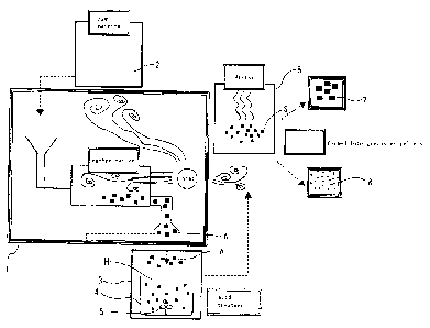
Figs. 1 and 2 show the first embodiment of this invention.
In Figs. 1 and 2, 1 indicates a carbonization furnace (an example of a
carbonization apparatus for carbonizing a raw material which comprises
plant(s)) for
carbonizing a ligneous material (an example of a raw material which comprises
plant(s)) 2
of plant(s), for example, natural fibers, including hemp, or lumber, without
activating
the material. Ligneous chips, for example, are used as the above described
material 2.
These ligiean chips are gained by processing a conifer, such as Japanese
cypress or cedar
having high water absorbency and have a size of no greater than, for example,
10 mm.
3 indicates facilities for acid treatment which contact an acid solution with
a
carbonized material that has been created by carbonization apparatus 1, and
has mixing
blades 5 inside a container 4 for containing an acid solution H, for example,
HCl and
H2SO4. The concentration of this acid solution is, for example, 5 mol/L.
Apparatus for
acid treatment 3 treats charcoal A in chip form that has been gained in
carbonization
furnace 1 with acid. In addition, (1) acid treated charcoal (an example of an
-22-
CA 02546477 2006-05-17
intermediate body) S which can be used immediately after acid treatment is
used as it is.
In addition, (2) the above described charcoal S may be neutralized with alkali
after
acid treatment if necessary, and in this case, (3) the neutralized acid
treated charcoal
S may be washed with water if necessary.
6 indicates a drier for drying acid treated charcoal S after acid treatment or
acid treated charcoal S after acid treatment, neutralization and washing with
water using
the heat discharged from the carbonization furnace. Here, drying may be
omitted if the
charcoal is used in a moist state. 6a (see Fig. 2) indicates a processing
portion for
processing the dried acid treated charcoal S. 7 indicates a product in pellet
form which
has been processed from the above described dried acid treated charcoal S, and
8
indicates a product which has been formed by crushing dried acid treated
charcoal S.
Here, the products are processed in different ways, depending on the
application. In
addition, another product, where dried acid treated charcoal S is stuck to an
unwoven
cloth, for example, can be cited, in addition to products 7 and 8.
Figs. 3 and 4 show the second embodiment of this invention.
In Figs. 3 and 4, acid treated Ca charcoal 32, which is an example of an anion
adsorbing carbon material is gained by drying ligneous material (an example of
a raw
material which comprises plant(s)) 2 of plant(s), for example, natural fibers,
including
hemp or lumber, using dryer 12 after immersion in a solution including calcium
ions (for
example, lime water C) which is prepared in a Ca introducing apparatus (an
example of an
apparatus for contacting a raw material which comprises plant(s) with a
solution including
calcium ions) 9, and subsequently, carbonizing the material in carbonization
furnace (an
example of a carbonization apparatus) 1 without activating the material, and
after that,
immersing the material in acid solution H, for example, HC1 or H2SO , using
apparatus
for acid treatment 3 for contacting the carbonized material which has been
created by
carbonization apparatus 1 with an acid solution, and furthermore, drying the
material
using dryer 6 and processing the material in processing portion 6a.
In this embodiment, ligneous chips are used as the above described material
originating from plant(s) (hereinafter, simply referred to as material) 2.
These
ligneous chips are gained by processing a conifer, such as Japanese cypress or
cedar
- 2 3 -
CA 02546477 2006-05-17
having high water absorbency and have a size of no greater than, for example,
10 mm. The
above described Ca introducing apparatus 9 is an apparatus for introducing Ca
into
li.gis chips 2, and is provided with a container 10 which contains a solution
including
calcium ions in which ligneous chips 2 are immersed. In this embodiment,
ligneous chips
2 are immersed in the lime water C, and ligneous chips 2 are immersed in the
lime water C
of a predetermined oonontration (for example, 5 weight %), and after that,
taken out from
container 10, and thereby, chips into which Ca has been introduced (an example
of an
intermediate body) 30 can be gained. In this case, it is preferable to drive
mixing
blades 10a which are provided inside container 10 while the ligneous chips are
immersed,
in order for the solution to sufficiently soak into ligneous chips 2, or for
calcium ions
to sufficiently react with a component of ligneous chips 2.
The gained chips 30 into which Ca has been introduced are dried using the
above
described dryer 12. In this embodiment, dryer 12 dries chips 30 into which Ca
has been
introduced using heat discharged fray the carbonization furnace. Here, the
efficiency in
processing improves when milk of lime is used. In addition, a calcium chloride
solution
or a calcium acetate solution can be used instead of lime water C or milk of
lime.
The dried chips 30 into which Ca has been introduced are carbonized in
carbonization furnace 1, so that Ca charcoal (an example of an intermediate
body made of a
carbonized material) 31 in chip form is gained. As for the conditions for
carbonization
in this embodiment, the temperature for carbonization is 650 C to 750 C.
The above described apparatus for acid treatment 3 is provided with a
container 4
which contains acid solution H, for example, HCl or H2SO4, and mixing blades 5
are
provided inside this container 4. The concentration of this acid solution H
is, for
example, 5 mol/L. In the above described apparatus for acid treatment 3, Ca
charcoal 31
in chip form that has been Pined in carbonization furnace 1 is treated with
acid, so that
acid treated Ca charcoal 32 is gained. In addition, it is preferable to drive
mixing
blades 5 which are provided inside container 4, so that dissolving of calcium
carbonate
(CaCO3) on the surface of Ca charcoal 31 in the acid is accelerated and
chloride ions
and calcium ions sufficiently react with functional groups on the surface of
the above
described Ca charcoal 31. The gained acid treated Ca charcoal (an example of
an
-24-
CA 02546477 2006-05-17
intermediate body made of a carbonized material) 32 is dried using the above
described
drier 6. In this embodiment, dryer 6 dries acid treated Ca charcoal 32 using
heat
discharged from the carbonization furrnace.
In addition, (1) acid treated Ca charcoal 32 which can be used immediately
after
acid treatment and drying is processed directly into a product as an anion
adsorbing
material. In addition, (2) acid treated Ca charcoal 32 may be neutralized with
alkali
after treatment with acid if necessary, and in this case, (3) the neutralized
acid treated
Ca charcoal may be washed with water if necessary. Here, drying may be omitted
in the
case where the product is used in a moist state.
7' indicates a product in pellet form which is gained by processing acid
treated
Ca charcoal 32, and 8' is a product which is formed by crushing acid treated
Ca charcoal
32. Here, the products are processed differently, as shown below, depending on
the
application. In addition, another product where acid treated Ca charcoal 32 is
stuck to
an unwoven cloth, for example, can be cited, in addition to products 7' and
8'. Here, in
some cases, chips 30 into which Ca has been introduced and Ca charcoal 31 are
prepared in
separate factories, and in such cases, manufacturing of acid treated Ca
charcoal 32 may
start in the middle of the process in each of the above described embodiments.
In
addition, acid treated Ca charcoal 32 can be used as it is, without
processing.
<Nitrate Nitrogen and Nitrite Nitrogen Adsorbing Test>
[Testing Method]
Five containers having 50 ml of nitrate solution and nitrite solution of the
ccnoentraticn of 50 mg/L (50 ppn), respectively, were prepared (standard
liquid), and five
types of the following samples were put into the corresponding containers for
each
standard liquid, and the containers were shaken for ten hours under the
conditions of, for
example, 200 ran at 20 C, and after that the concentration of nitrate nitrogen
and the
concentration of nitrite nitrogen in the above described nitrate solution and
nitrite
solution were respectively measured and the amount of adsorption was
calculated:
(1) 200 mg of charcoal, which was gained by carbonizing ligneam chips 2 at 700
C
(hereinafter simply referred to as charcoal) and used as a comparative
example,
(2) 200 mg of iron chloride charcoal, which was gained by immersing charcoal
-25-
CA 02546477 2006-05-17
which had been gained by carbonizing ligneous chips 2 at 700 C in 1 mol/L of
an FeC13
solution and after that washing the charcoal with water, and used as a
comparative
example,
(3) 200 mg of acid treated charcoal, which was gained by immersing charcoal
which
had been gained by carbonizing ligneous chips 2 at 700 C in 5 mol/L of an HC1
solution
and after that washing the charcoal with water,
(4) 200 mg of acid treated Ca charcoal 32 (anion adsorbing carbon material),
which was gained by immersing charcoal which had been gained by immersing
ligneous chips 2
in 5 weight % of lime water, and after that, carbonizing the chips at 70 C in
5 mol/L of
an HC1 solution, and
(5) 200 mg of an anion exchange resin, which was used as a comparative
example.
[Results]
Fig. 5 shows the comparison in the adsorbing abilities of nitrate nitrogen and
nitride nitrogen among the above described respective samples. The Charcoal of
(1) which
was carbonized at 700 C barely adsorbed nitrate nitrogen or nitrite nitrogen,
while the
iron chloride charcoal of (2) adsorbed 2.75 mg/g and 2.35 mg/g of nitrate
nitrogen and
nitrite nitrogen, respectively. In addition, acid treated charcoal S of (3)
adsorbed 2.50
mg/g and 2.20 mg/g of nitrate nitrogen and nitrite nitrogen, respectively. The
anion
exchange resin of (5) adsorbed 10.80 mg/g and 10.00 mg/g of nitrate nitrogen
and nitrite
nitrogen, respectively.
Meanwhile acid treated Ca charcoal 32 of (4), which was gained by immersing
ligneous chips 2 in lime water C, and after that, carbonizing the chips, and
subsequently
immersing the chips in an HC1 solution, adsorbed 10.75 mg/g and 9.80 mg/g of
nitrate
nitrogen and nitrite nitrogen, respectively, and exhibited the adsorption
ability which
was equal to or greater than that of the anion exchange resin of (5).
In addition, the mechanism for the above described acid treated Ca charcoal 32
to
adsorb nitrate ions is considered as follows. As shown in Fig. 10(A), when
acid treated
Ca charcoal 32 (anion adsorbing carbon material) is immersed in a nitrate
solution L, for
example, nitrate ions in nitrate solution L are exchanged with chloride ions
[see Fig.
10(B)] which have combined with functional groups on the surface of the walls
of the
-26-
CA 02546477 2006-05-17
micro pores in acid treated Ca charcoal 32 directly or via calcium ions [see
Fig. 10(C)],
and thus, the nitrate ions adsorbed by acid treated Ca charooal 32 [see Fig.
10(D)]. Fig.
10(E) shows a change in acid treated Ca charcoal 32 shown in Fig. 10(D) when
this is
immersed in a KC1 (or NaCl) solution. That is to say, the acid treated Ca
charcoal 32
which has adsorbed nitrate ions can repeatedly be restored by exchanging
nitrate ions
with chloride ions in the KCl (or NaCl) solution. In the following, this
restoration
test is described.
<Restoration Test>
[Testing Method]
Samples of acid treated charcoal S and acid treated Ca charcoal 32 after the
above described nitrate nitrogen adsorbing test had been carried out, were
washed with 1
mol/L of a KC1 (or NaCl) solution, and furthermore, it was washed with water.
Subsequently, the standard liquid was exchanged and 50 ml (milliliter) of a
nitrate
solution of which the concentration of nitrate nitrogen was 50 mg/L was
prepared as a
standard liquid, and the first restoration test was carried out on the above
described 200
mg of the samples which were washed with water. That is to say, the above
described
samples were put into a nitrate solution and the containers were shaken for
ten hours
under the conditions of, for example, 200 rpm at 20 C, and after that, the
concentration
of nitrate nitrogen in the above described nitrate solution was measured and
the amount of
adsorption was calculated, and in this manner, the first restoration test was
carried out
on the above described samples.
Next, the above described samples which were used in the first restoration
test
were washed with a KC1 (or NaCl) solution of 1 mol/L, and furthermore, it was
washed with
water. Subsequently, the standard liquid was exchanged and 50 ml (milliliter)
of a
nitrate solution of which the concentration of nitrate nitrogen was 50 mg/L
was prepared
and a restoration test was carried out on 200 ml of the above described
samples which had
been washed with water as described above. That is to say, the above described
samples
were put into 50 ml (milliliter) of a nitrate solution and the containers were
shaken for
ten hours under the conditions of, for example, 200 rpm at 20 C, and after
that, the
concentration of nitrate nitrogen in the above described nitrate solution was
measured and
-27-
CA 02546477 2006-05-17
the amount of adsorption was calculated, and in this manner, the second
restoration test
was carried out on the above described samples. This process was repeated two
additional
times.
[Results]
Amount of nitrate nitrogen adsorbed by acid treated charcoal S
Initial time 2.5 mg/g
First restoration time 2.5 mg/g
Second restoration time 2.4 mg/g
Third restoration time 2.5 mg/g
Amount of nitrate nitrogen adsorbed by acid treated Ca charcoal 32
Initial time 10.8 mg/g
First restoration time 10.6 mg/g
Second restoration time 10.9 mg/g
Third restoration time 10.7 mg/g
It can be seen from the above that the above described acid treated charcoal S
and acid treated Ca charcoal 32 after use can be washed with a dense KC1 (or
NaCl)
solution, respectively, and furthermore, it was washed with water, and
thereby, can be
restored. That is to say, it was found that acid treated charcoal S and acid
treated Ca
charcoal (anion adsorbing carbon material) 32 which had adsorbed nitrate
nitrogen
(anions) in the nitrate nitrogen adsorbing test were respectively washed with
a KC1 (or
NaCl) solution, and furthermore, it was washed with water, and thereby,
nitrate nitrogen
(anions) which had been adsorbed in the nitrate nitrogen adsorbing test was
removed and
Cl- was combined instead of the removed nitrate nitrogen (anions), and thus,
acid treated
charcoal S and acid treated Ca charcoal 32 (anion adsorbing charcoal material)
were
respectively restored. That is to say, it was confirmed that acid treated
charcoal S and
acid treated Ca charcoal 32 (anion adsorbing carbon material) are respectively
washed with
a KC1 (or NaCl) solution and then washed with water after each use, and
thereby, they can
be used a number of times. Here, in the case where nitrite nitrogen is
adsorbed and acid
treated charcoal S and acid treated Ca charcoal are respectively used as an
anion
adsorbing carbon material, the restoration principle is the same.
-28-
CA 02546477 2006-05-17
Fluoride Ion Adsorbing Test>
[Testing Method]
50 ml (milliliter) of a solution of which the concentration of fluoride ions
was
50 mg/L (standard liquid) was prepared in separate containers, and five types
of the
following samples were put into the corresponding containers for each standard
liquid,
and the containers were shaken for ten hours under the conditions of, for
example, 200 rpm
at 20 C, and after that, the concentration of .fluoride ions in the above
described
solution were respectively measured and the amount of adsorption was
calculated:
(1) 100 mg of charcoal, which was gained by carbonizing ligneous chips 2 at
700 C
(hereinafter simply referred to as charcoal) and used as a comparative
example,
(2) 100 mg of iron chloride charcoal, which was gained by immersing charcoal
which had been gained by carbonizing ligneous chips 2 at 700 C in 1 mol/L of
an FeCl3
solution and after that washing the charcoal with water, and used as a
comparative
example,
(3) 100 mg of acid treated charcoal, which was gained by immersing charcoal
which
had been gained by carbonizing ligneous chips 2 at 700 C in 5 mol/L of an HC1
solution
and after that washing the charcoal with water,
(4) 100 mg of an anion adsorbing carbon material (acid treated Ca charcoal
32),
which was gained by immersing charcoal which had been gained by immersing
ligneous chips
2 in 5 weight % of lime water, and after that, carbonizing the chips at 700 C
in 5 mol/L
of an HC1 solution, and
(5) 100 mg of an anion exchange resin, which was used as a cxmpxirative
example.
[Results]
Fig. 6 shows the comparison in the fluoride ion adsorbing ability among the
above
described respective samples.
The charcoal of (1) carbonized at 700 C barely adsorbed chloride ions, while
the
ion chloride charcoal of (2) adsorbed 7.50 mg/g of fluoride ions. In addition,
acid
treated charcoal s of (3) adsorbed 5.00 mg/g of fluoride ions. The anion
exchange resin
of (5) adsorbed 8.50 mg/g of fluoride ions.
Meanwhile, acid treated Ca charcoal 32 of (4) which had been gained by
immersing
-29-
CA 02546477 2006-05-17
ligneous chips 2 in lime water, and after that, carbonizing the chips, and
subsequently,
immersing the chips in an HM solution adsorbed 19.00 mg/g of fluoride ions and
exhibited
adsorption ability which greatly exceeded the anion exchange resin of (5).
Restoration Test>
[Testing Method]
Next, the samples of acid treated charcoal S and acid treated Ca charcoal 32
after the above described fluorine adsorbing test had been carried out, were
washed with 1
mol/L of a hydrochloric acid (or sulfuric acid), and furthermore, it was
washed with
water. Subsequently, the standard liquid was exchanged and 50 ml (milliliter)
of a
solution of which the concentration of fluoride ions was 50 mg/L was prepared,
and the
first restoration test was carried out on the above described 200 mg of the
samples which
had been washed with water. That is to say, the above described samples were
put into
the above described solution and the containers were shaken for ten hours
under the
conditions of 200 rpm at 20 C, and after that, the concentration of fluoride
ions in the
above described solution was measured and the amount of adsorption was
calculated, and in
this manner, the first restoration test was carried out on the above described
samples.
Next, the above described samples which had been used in the first restoration
test were
washed with 1 mol/L of a hydrochloric acid (or sulfuric acid), and
furthermore, it was
washed with water. Subsequently, the standard solution was exchanged and 50 ml
(milliliter) of a solution of which the concentration of fluoride ions was 50
mg/L was
prepared as described above, and a restoration test was carried out on 200 mg
of the above
described samples which had been washed with water as described above. That is
to say,
the above described samples were put into the containers of 50 ml (milliliter)
of the
above described solution, and the containers were shaken for ten hours under
the
conditions of, for example, 200 rpm at 20 C, and after that, the concentration
of
fluoride ions in the above described solution was measured and the amount of
adsorption
was calculated, and in this manner, the second restoration test was carried
out on the
above described samples. This process was repeated two additional times.
[Results]
Amount of fluoride ions adsorbed by acid treated charcoal S
-30-
CA 02546477 2006-05-17
Initial time 2.5 mg/g
First restoration time 2.5 mg/g
Second restoration time 2.4 mg/g
Third restoration time 2.5 mg/g
Amount of fluoride ions adsorbed by acid treated Ca charcoal 32
Initial time 18.7 mg/g
First restoration time 18.2 mg/g
Second restoration time 18.9 mg/g
Third restoration time 18.6 mg/g
It can be seen from the above that the above described acid treated charcoal S
and acid treated Ca charcoal 32 after use were respectively washed with a
dense
hydrochloric acid (or sulfuric acid), and furthermore, it was washed with
water, and
thereby, were restored. That is to say, it was found that acid treated
charcoal S and
acid treated Ca charcoal 32 (anion adsorbing carbon material) which had
adsorbed fluoride
ions (anions) in the fluorine adsorbing test were respectively washed with a
hydrochloric
acid (or sulfuric acid), and furthermore, it was washed with water, and
thereby, the
fluoride ions (anions) which had been adsorbed in the fluoride ion adsorbing
test were
removed and Cl- (or S042-) was combined instead of the removed fluoride ions
(anions) ,
and thus, acid treated charcoal S and acid treated Ca charcoal 32 (anion
adsorbing carbon
material) were restored, respectively. That is to say, it was confirmed that
acid
treated charcoal S and acid treated Ca charcoal 32 (anion adsorbing carbon
material) which
are once used can be washed with a hydrochloric acid (or sulfuric acid), and
furthermore,
it was washed with water, after each use, and thereby, can be used a number of
times.
Figs. 11 to 20 show the third embodiment of this invention. Fig. 11
schematically shows an example ofa facilities for manufacturing an anion
adsorbing carbon
material (hereinafter referred to as carbon material) 37 according to the
third embodiment
of this invention, and in this figure, 2 indicates a plant material which is
ligneous
chips in this embodiment. These ligneous chips 2 are gained by processing a
conifer,
such as Japanese cypress or cedar having high water absorbency and have an
appropriate
size of no greater than, for example, 50 mm.
-31-
CA 02546477 2006-05-17
In addition, the above described ligneous chips 2 are fed to a process tank 20
(apparatus for contacting a material with a solution including a metal
chloride) which
contain a metal chloride solution (CaCl 2 solution in this embodiment) M
having an
appropriate concentration, and within this process tank 20, a process for
introducing a
metal chloride (CaC1 2 in this embodiment) is carried out on ligneous chips 2
so that
chips into which a metal chloride has been introduced (an example of an
intermediate body)
35 are formed. Here, 20a indicates mixing blades which are provided within
process tank
20 and are driven by a motor (not shown) so as to rotate, and thus, are used
when stirring
a liquid or the like within process tank 20. Here, it is preferable to add a
slight
amount of Ca(CH) 2 to the metal chloride solution in order to enhance the
anion adsorbing
ability.
Chips 35 into which a metal chloride has been introduced and which have been
gained as described above are dried using a drier 12, and after that, fed to a
carbonization process furnace 1 (carbonization apparatus) where a
carbonization process
is carried out on the chips without activation. Here, the above described
drier 12 is an
example of a drying area for drying chips 35 into which a metal chloride has
been
introduced and which are an intermediate body for gaining a carbon material
37, and is
formed such that the heat discharged from carbonization prod furnace 1 is used
for the
above described drying.
The main body 1a of the carbonization furnace which is heated by an
appropriate
heat source 21 is contained inside the above described carbonization process
furnace 1.
In addition, chips 35 into which a metal chloride has been introduced are
supplied to the
inside of the above described main body la of the carbonization furnace
through an
introduction portion 1b, and are heated at an appropriate temperature
(described below)
and for an appropriate period of time (described below) so as to be carbonized
and
converted to a carbonized material, and this carbonized material is discharged
to the
outside of the main body 1a of the carbonization furnace through a discharging
portion 1c
as carbon material 36, which is an example of an intermediate body.
After that, the above described carbon material 36 is fed to a process tank 22
(apparatus for enhancing the anion adsorbing ability) which contains water or
an HC1
-32-
CA 02546477 2006-05-17
solution (hydrochloric acid) H, and a process for contacting (immersing)
carbon material
36 with (in) water or HC1 solution H is carried out within this process tank
22. Here, 23
indicates mixing blades which are provided within process tank 22, and are
driven by a
motor (not shown) so as to rotate, and thus, are used when stirring a liquid
or the like
within process tank 22. In some cases, a process for contacting a material
with water is
carried out after a process for contacting the material with an acid, or they
may be
carried out in the opposite order.
Next, carbon material (an example of an intermediate body) 37 which has been
immersed in water or HCl solution H is fed to a drier 24 so as to be dried,
and after
that, are formed into grains (pellets) 7" having an appropriate diameter or
further
crushed into powder 8" which is finer than grains. Here, the above described
drier 24 is
an example of a drying area for drying carbon material 37 which is an
intermediate body
before being processed to pellets 7" or powder 8", and is formed so that the
heat that is
discharged from carbonization process furnace 1 is used for the above
described drying.
Here, Fig. 12(A) shows the carbon material 37 which has been formed into chips
having a length of approximately 10 mm and Fig. 12(B) shows an example of
grains (pellets)
7" having an appropriate diameter which have been formed from the above
described carbon
material 37 in chip form.
Next, an example of a procedure for gaining carbon material 37 from plant
material 2 using the facilities shown in Fig. 11 is described in detail in
reference to
Figs. 11 and 13. First, ligxous chips 2 which have been gained by processing a
conifer,
such as Japanese cypress or cedar having high water absorbency and have a size
of no
greater than, for example, 10 mm are prepared (Step Si).
Next, the above described ligneous chips 2 are immersed in CaC12 solution M
which
has been prepared so as to have 1 weight % to 20 weight % within process tank
20 for no
less than, for example, three hours. It is preferable to rotate mixing blades
20a while
these ligneous chips 2 are immersed. As a result, CaCl2 solution M soaks into
ligneous
chips 2, and thus, chips 35 into which a metal chloride has been introduced,
that is,
ligneous chips 2 into which calcium ions and chloride ions have been
introduced are
gained (Step S2).
-33-
CA 02546477 2006-05-17
In addition, the above described chips 35 into which a metal chloride has been
introduced are fed to drier 12 so as to be dried (Step S3).
After that, the above described ligneous chips 2 are supplied to main body 1 a
of
the carbonization furnace in carbonation process furnace 1, and is heated for
approximately one hour in a temperature range (700 C in this embodiment) from
400 C to
1000 C so that a carbonization process is carried out (Step S4). As a result,
the carbon
material 37 is gained.
The above described carbon material 37 is supplied to process tank 22 and is
immersed and processed in HC1 solution H that has been prepared so as to have
0.01 mol/L
to 11 mol/L (for example, 5 mol/L) within process tank 22 (Step S5). In this
case, it is
preferable to rotate mixing blades 23, and thereby, extra crystal of the metal
chloride
(CaC12) which remains within carbon material 37 can be removed and at the same
time
chloride ions can further be added, and thus, desired carbon material 37 is
gained.
In addition, carbon material 37 after the above described immersion process is
dried in general using drier 24 (Step S6). In this case, carbon material 37
may be
directly fed to drier 24, or a neutralization process such as immersion in an
appropriate
alkaline solution may be carried out, and additionally, the carbon material
may be washed
with water after the neutralization process. Here, in the case where carbon
material 37
is used in a moist state, it may not be dried.
In addition, though carbon material 37 in chip form after drying as described
above can be used as is, the material has been formed into grains (pellets) 7"
having an
appropriate diameter or powder 8" which has finer particles using an
appropriate
processing machine in this embodiment (Step S7). In addition, it is possible
to use the
above described carbon material 37 in a state where, for example, it is stuck
to an
unwoven cloth in addition to being used as is.
Here, the above described carbon material 37 is not necessarily manufactured
by
carrying out all the above described Steps S1 to S7 within the same factory.
In the case
where several steps from among the above described Steps Si to S7 have been
carried out
during the manufacture in another factory, or the like, carbon material 37 may
be
manufactured by starting from a step in the middle.
-34-
CA 02546477 2006-05-17
Here, this invention is not limited to any of the above described embodiments,
and can be implemented by modifying in various manners. BaC12, t4iC12, and the
like,
for example, can be cited as the metal chloride, though CaC12, which allows
the anio n
adsorbing carbon material having the highest performance to be gained, is used
in the
above described embodiments.
In addition, in the above described embodiments though a process for
contacting
carbon material 37 with HC1 solution H is carried out within process tank 22,
water may
be used instead of HC1 solution H. In this case, chloride ions are not added
and extra
crystal of a metal chloride which remains within carbon material 37 is simply
moved.
Furthermore, in the above described embodiments, though carbon material 37 is
fed to
process tank 22 after it has been gained by carrying out a carbonization
process on chips
35 into which a metal chloride has been introduced in carbonization process
furnace 1, it
is not necessary to feed the carbon material to process tank 22. In this case,
it
becomes unnecessary to feed the above described carbon material 37 to drier
24, and
therefore, the above described Steps S5 and S6 are omitted from the
manufacturing method
for carbon material 37. In addition, in this case the manufacturing method for
carbon
material 37 may be completed with Steps S1 to S4, or Step S7 may be carried
out
afterwards.
Next, a test that was carried in order to check the performance of the above
described carbon material 37 of adsorbing nitrate nitrogen and nitrite
nitrogen is
described. A test method and test results of the performance of adsorbing
nitrate
nitrogen and nitrite nitrogen are described in the following.
First, two sets of samples (1) to (7), each of which was 200 mg and of which
the
total number of samples in one set was 7 were prepared as shown in the
following. That is
to say, two sets of the following samples, of which the total number in one
set was 7,
were prepared:
(1) charcoal which was gained by heating and carbonizing ligneous chips 2 for
1 hour at
700 C ,
(2) iron chloride charcoal which was gained by heating and carbonizing
ligneous chips 2
for 1 hour at 700 C , and after that immersing the chips in an FeC13 solution
of 1 mol/L
-35-
CA 02546477 2006-05-17
and then washing the chips with water,
(3) an anion exchange resin,
(4) BaC12 charcoal which was gained by immersing ligneous chips 2 in a BaC12
solution of
weight %, and after that, heating and carbonizing the chips for one hour at
700 C,
(5) HCl processed BaC12 charcoal which was gained by immersing ligneous chips
2 in a BaCl
2 solution of 10 weight %, and after that, heating and carbonizing the chips
for one hour
at 700 C, and furthermore, immersing and processing the chips in an HC1
solution of 5
mal/L,
(6) CaCl2 charcoal which was gained by immersing ligneous chips 2 in a CaCl2
solution of
10 weight %, and after that, heating and carbonizing the chips for one hour at
700 C, and
(7) HCl processed CaC12 charcoal. which was gained by immersing ligneous chips
2 in a CaCl
2 solution of 10 weight %, and after that, heating and carbonizing the chips
for one hour
at 700 C, and furthermore, immersing and processing the chips in an HCl
solution of 5
cool/L. Here, samples (4) to (7) corresponded to the above described carbon
material 37
and samples (1) to (3) were provided for comparison with carbon material 37.
Then samples in one set were individually put into 50 mL of nitrate nitrogen
solution (first standard liquid) of which the concentration of nitrate
nitrogen was 50
mg/L (50 ppm) and samples in the other set were individually put into 50 mL of
nitrite
nitrogen solution (second standard liquid) of which the concentration of
nitrite nitrogen
was 50 mg/L (50 ppm). After that, the containers of the solutions were shaken
for ten
hours under the conditions of 200 rpm at 20 C, and then, the concentration of
nitrate
nitrogen in the first standard liquid and the concentration of nitrite
nitrogen in the
second standard liquid were respectively measured, and the amount of nitrate
nitrogen and
nitrite nitrogen which were adsorbed by each sample was calculated.
Fig. 18 shows the comparison results in the nitrate nitrogen adsorbing ability
and nitrite nitrogen adsorbing ability among the respective samples which were
gained in
the above described test. Here, this figure shows the amount of nitrate
nitrogen and
nitrite nitrogen adsorbed by each sample is shown in pairs of bars in a graph,
where the
bars on the left show the amount of adsorbed nitrate nitrogen and the bars on
the right
-36-
CA 02546477 2006-05-17
show the amount of adsorbed nitrite nitrogen. It can be seen from the results
shown in
this graph that all the samples of the present invention have high nitrate
nitrogen
adsorbing ability and nitrite nitrogen adsorbing ability. Furthermore, the
amount of
adsorbed nitrate nitrogen and nitrite nitrogen is compared between BaCl2
charcoal of (4)
and HC1 processed BaC12 charcoal of (5) and the amount of adsorbed nitrate
nitrogen and
nitrite nitrogen is compared between CaC12 charcoal of (6) and HC1 processed
CaC12
charcoal of (7), and thereby, it can be seen that it is better to carry out a
process (HC1
process) for immersing carbon material 37 in an HC1 solution in order to
enhance the
nitrate nitrogen/nitrite nitrogen adsorbing ability of carbon material 37.
However,
carbon material 37 having a sufficiently high nitrate nitrogen/nitrite
nitrogen adsorbing
ability can be gained without carrying out an HC1 process, and in this case,
carbon
material 37 can be manufactured at a cost which is lower by the portion for
carrying out
a process for contacting the material with an HCl solution.
Here, the above described carbon material 37 adsorbs, for example, nitrate
ions,
and this is considered to be become, as shown in Fig. 17(A), when carbon
material (CaC12
charcoal) 37 is immersed in a nitrate solution L, chloride ions which has been
combined
with functional groups on the surface of carbon material 37 directly or via
calcium ions
(see Fig. 17(B)) and nitrate ions in nitrate solution L are exchanged (see
Fig. 17(C)) so
that nitrate ions are adsorbed by carbon material 37 (see Fig. 17(D)).
In addition, Fig. 17(E) shows a state of carbon material 37, which was in a
state
shown in Fig. 17(D) adsorbing nitrate ions, after being immersed in a chloride
solution
having a high concentration (for example, a metal chloride solution of KC1 or
NaCl, or
HCl solution H). That is to say, the nitrate ions which have been adsorbed by
carbon
material 37 are exchanged with chloride ions in chloride solution, and
thereby, carbon
material 37 is restored and becomes a state where it can adsorb anions such as
nitrate
ions. That is to say, carbon material 37 of this invention is not always
limited to those
which are newly gained in accordance with the above described manufacturing
method, but
may be those which are gained (that is to say, restored) by moving the
adsorbed anions
(for example, nitrate ions) frcm carbon material 37 which has been gained in
accordance
with the above described manufacturing method and has adsorbed anions (nitrate
ions) and
-37-
CA 02546477 2006-05-17
combining anions (chloride ions in this embodiment) which can be ion exchanged
with
anions (for example, nitrate ions) of the next object of adsorption with the
carbon
material instead of the above described removed anion (nitrate ions). In
addition, in
the case where sulfuric acid is used instead of the above described chloride
solution,
nitrate ions are ion exchanged with sulfate ions instead of the above
described chloride
ions.
Next, a test which was carried out in order to check how the concentration of
metal chloride solution (CaC12 solution) M into which ligneous chips 2 are
immersed in
the above described Step S2 effects the anion absorbing ability of carbon
material 37
after the manufacture is described. In the above described test, carbon
material 37 which
was gained by immersing ligneous chips 2 in CaC12 solution M, and after that
carbonizing
the chips by heating for one hour at 700'C, and then, washing the chips with
water, was
put into 50 mL of nitrate nitrogen solution (standard liquid) of which the
concentration
of nitrate nitrogen was 50 mg/L (50 ppm), and thus, the nitrate nitrogen
adsorbing
ability of the above described carbon material 37 was checked, where CaC12
solutions of
which the concentrations were 1 weight %, 3 weight %, 5 weight %, 7 weight %,
10 weight
%, 12 weight %, 14 weight %, 17 weight % and 20 weight % were used as the
above described
CaC12 solution M. Here, the amount of carbon material 37 which was added to
each
solution was 200 mg. In addition, for oanparison, 200 mg of carbon material
37, which was
gained by immersing ligneous chips 2 in 10 weight % of CaC12 solution M, and
after that,
heating and carbonizing the chips for one hour at 700 C, and then carrying out
an HC1
process, was used so that the nitrate nitrogen adsorbing ability thereof was
checked.
The results of the above described test are shown in Fig. 19.
As is clear from the results shown in Fig. 19, the anion adsorbing ability of
carbon material 37 does not increase in proportion to the concentration of the
CaC12
solution, and it can be said that it is most preferable for the concentration
to be
approximately 10 weight % when taking cost and the like into consideration. In
addition,
it can be seen from the results shown in this Fig. 19 that it is better to
carry out an
HC1 process on carbon material 37 in order to enhance the anion adsorbing
ability of
carbon material 37.
-38-
CA 02546477 2006-05-17
Next, the restoration test, in which carbon material 37 that had been used to
adsorb nitrate nitrogen was restored using a KC1 (or NaCl) solution and which
was carried
out to check the nitrate nitrogen adsorbing ability of the restored carbon
material 37,
is described.
First, 200 mg of CaC12 charcoal, which had been gained by immersing ligneous
chips 2 in a CaC12 solution of 10 weight %, and after that, heating and
carbonizing the
chips for one hour at 70 C, was prepared as carbon material 37. Then, this
CaC12
charcoal was put in 50 mL of a nitrate nitrogen solution (standard liquid) of
which the
concentration of nitrate nitrogen was 50 mg/L (50 ppn), and the container was
shaken for
ten hours under the conditions of 200 rpm at 20 C , and after that, the
concentration of
the nitrate nitrogen in the above described standard liquid was measured and
the amount
of nitrate nitrogen adsorbed by the above described CaC12 charcoal was
calculated
(initial time).
Subsequently, the above described CaC12 charcoal was washed with a KC1 (or
NaCl)
solution of 1 mol/L, and furthermore, it was washed with water and then
restored. After
that, the restored CaW12 charcoal was put in a newly prepared standard liquid
(that is to
say, 50 mL of a nitrate nitrogen solution of which the concentration of
nitrate nitrogen
was 50 mg/L), and the container was shaken for ten hours under the conditions
of 200 rpm
at 20 C, and after that, the concentration of nitrate nitrogen in the above
described
standard liquid was measured and the amount of nitrate nitrogen adsorbed by
the above
described CaC12 charcoal was calculated. In addition, the process, starting
from the
restoration of this CaC12 charcoal up to the calculation of the amount of
nitrate nitrogen
adsorbed by the CaC12 charcoal, was carried out three times in total (first
restoration
time to third time).
The results of the above described restoration test, that is to say, the
amount
of nitrate nitrogen adsorbed by the CaC12 charcoal, was as follows:
Initial time 9.5 mg/g
First restoration time 9.0 mg/g
Second restoration time 9.1 mg/g
Third restoration time 8.8 mg/g
-39-
CA 02546477 2006-05-17
It was confirmed from the above description that carbon material 37 (CaC12
charcoal),
which had been used to adsorb nitrate nitrogen, was restored when washed with
a dense KC1
(or NaCl) solution, and furthermore, it was washed with water. This is
considered to be
because nitrate nitrogen was removed from the CaC12 charcoal when the CaC12
charcoal,
which had adsorbed nitrate nitrogen, was washed with a KC1 (or NaCl) solution,
and
furthermore, it was washed with water, and Cl- combined with the functional
groups
instead of this removed nitrate nitrogen. In addition, it was confirmed from
the results
of the above described restoration test that carbon material 37 (CaC12
tharccal) could be
used a number of times to adsorb nitrate nitrogen in the case where the carbon
material
was restored by washing it with a KC1 (or NaCl) solution, and then washing it
with water.
Here, the restoring principle is the same in the case where the above
described carbon
material 37 (CaC12 charcoal) is used to adsorb nitrite nitrogen.
Next, HC1 processed CaC12 charcoal, which had been gained by immersing
ligneous
chips 2 in a CaC12 solution of 10 weight %, and after that, heating and
carbonizing the
chips for one hour at 70 C, and then, processing the chips through the
immersion in an
HC1 solution of 5 mol/L, was used as carbon material 37, and the results of
the
restoration test, which was carried out in the same manner as described above
on this HC1
processed CaC12 charcoal, are shown as follows.
The results of the above described restoration test, that is to say, the
amount
of nitrate nitrogen adsorbed by the HCl processed CaC12 charcoal, was as
follows:
Initial time 11.0 mg/g
First restoration time 11.0 mg/g
Second restoration time 10.8 mg/g
Third restoration time 10.8 mg/g
It was confirmed from the above description that carbon material 37 (HC1
Processed CaCl2
charcoal..), which was gained by processing the chips after carbonization
through immersion
in an HCl solution, was also restored by washing it with a dense KC1 (or NaCl)
solution,
and furthermore, washing it with water after it was used to adsorb nitrate
nitrogen. In
addition, it was confirmed that the nitrate nitrogen adsorbing ability of the
HC1
processed CaCl2 charcoal, which increased by processing the char-coal through
immersion in
-40-
CA 02546477 2006-05-17
an HCl solution, was maintained (kept increasing) even when the HC1 processed
CaC12
charcoal was repeatedly restored by washing it with a KC1 (or NaCl) solution,
and then
washing it with water.
Next, the test which was carried out in order to check the fluoride ion
adsorbing
ability of the above described carbon material 37 is described. First, in
order to carry
out this test, one set of samples (1) to (7), which were the same as those
used in the
above described test of nitrate nitrogen and nitrite nitrogen adsorption
ability, and of
which the total number of samples was 7 with each having 50 mg, was prepared.
Then,
these samples were individually put into 50 mL of a solution (standard liquid)
of which
the concentration of fluoride ions was 50 mg/L (50 ppm), and the containers
were shaken
for ten hours under the conditions of 200 rpm at 20 C, and after that, each
concentration
of fluoride ions in the standard liquid was measured, and the amount of
fluoride ions
adsorbed by each sample was calculated.
Fig. 20 shows the results of comparison in the fluoride ion adsorbing ability
among the respective samples which were gained in the above described test. It
can be
seen from the results shown in this figure that the samples of the present
invention all
had a high fluoride ion adsorbing ability. Furthermore, the amount of fluoride
ions
adsorbed by the BaC12 charcoal of (4) and the amount of fluoride ions adsorbed
by the HCl
processed BaCl2 charcoal of (5) are cared, and in addition, the amount of
fluoride ions
adsorbed by the CaCl2 charcoal of (6) and the amount of fluoride ions adsorbed
by the
HCl processed CaCl2 charcoal of (7) are compared, and thereby, it can be seen
that it is
better to carry out a process (HC1 process) of immersing carbon material 37 in
an HC1
solution in order to enhance the fluoride ion adsorbing ability of carbon
material 37.
However, carbon material 37, having a sufficiently high fluoride ion adsorbing
ability,
can be gained without carrying out an HC1 process, and in this case, carbon
material 37
can be manufactured at a oast that is lower by the portion for carrying out a
process for
contacting the carbon material with an HC1 solution.
Next, the restoration test, in which carbon material 37 that had been used to
adsorb fluoride ions was restored using a hydrochloric acid (or sulfuric acid)
and which
was carried out to check the fluoride ion adsorbing ability of the restored
carbon
-41-
CA 02546477 2006-05-17
material 37, is described.
First, 200 mg of CaC12 charcoal, which had been gained by immersing ligneous
chips 2 in a CaC12 solution of 10 weight %, and after that, heating and
carbonizing the
chips for one hour at 70 C, was prepared as carbon material 37. Then, this
CaC12
charcoal was put in 50 mL of a solution (standard liquid) of which the
concentration of
fluoride ions was 50 mg/L (50 ppn), and the container was shaken for ten hours
under the
conditions of 200 rpm at 20 C, and after that, the concentration of the
fluoride ions in
the above described standard liquid was measured and the amount of fluoride
ions adsorbed
by the above described CaC12 charcoal was calculated (initial time).
Subsequently, the above described CaCl2 charcoal was washed with a
hydrochloric
acid (or sulfuric acid) of 1 mol/L, and furthermore, it was washed with water
and then
restored. After that, the restored CaCl2 charcoal was put in a newly prepared
standard
liquid (that is to say, 50 mL of a solution of which the concentration of
fluoride ions
was 50 mg/L), and the container was shaken for ten hours under the conditions
of 200 rpm
at 20 C, and after that, the concentration of fluoride ions in the above
described
standard liquid was measured and the amount of fluoride ions adsorbed by the
above
described CaCl2 charcoal was calculated. In addition, the process, starting
from the
restoration of this CaC12 charcoal up to the calculation of the amount of
fluoride ions
adsorbed by the CaCl2 charcoal, was carried out three times in total (first
restoration
time to third time).
The results of the above described restoration test, that is to say, the
amount
of fluoride ions adsorbed by the CaC12 charcoal, was as follows:
Initial time 22.5 mg/g
First restoration time 22.4 mg/g
Second restoration time 21.7 mg/g
Third restoration time 21.9 mg/g
It was confirmed from the above description that carbon material 37 (CaC12
charcoal),
which had been used to adsorb fluoride ions, was restored when washed with a
dense
hydrochloric acid (or sulfuric acid), and fire, it was washed with water. This
is
considered to be because fluoride ions were removed from the CaCl2 charcoal
when the CaCl
-42-
CA 02546477 2006-05-17
2 charcoal, which had adsorbed the fluoride ions, was washed with a
hydrochloric acid (or
sulfuric acid), and furthermore, it was washed with water, and Cl- (or S0#2-)
combined
with the functional groups instead of these removed fluoride ions. In
addition, it was
confirmed from the results of the above described restoration test that carbon
material 37
(CaC12 charcoal) could be used a number of times to adsorb fluoride ions in
the case
where the carbon material was restored by washing it with a hydrochloric acid
(or sulfuric
acid), and then washing it with water.
Next, HC1 processed CaCl2 charcoal, which had been gained by immersing
ligneous
chips 2 in a CaCl2 solution of 10 weight %, and after that, heating and
carbonizing the
chips for one hour at 70 C, and then, processing the chips through the
immersion in an
HC1 solution of 5 mol/L, was used as carbon material 37, and the results of
the
restoration test, which was carried out in the same manner as described above
on this HCl
processed CaC12 charcoal, are shown as follows.
The results of the above described restoration test, that is to say, the
amount
of fluoride ions adsorbed by the HCl processed CaC12 charcoal, was as follows:
Initial time 32.0 mg/g
First restoration time 31.5 mg/g
Second restoration time 31.4 mg/g
Third restoration time 31.2 mg/g
It was confirmed from the above description that carbon material 37 (HC1
processed CaC12
charcoal), which was gained by processing the chips after carbonization
through immersion
in an HCl solution, was also restored by washing it with a dense hydrochloric
acid (or
sulfuric acid) solution, and furthermore, washing it with water after it was
used to
adsorb fluoride ions. In addition, it was confirmed that the fluoride ion
adsorbing
ability of the HCl processed CaC12 charcoal, which increased by processing the
charcoal
t ro gh immersion in an HC1 solution, was maintained (kept increasing) even
when the HCl
processed CaW12 charcoal was repeatedly restored by washing it with a
hydrochloric acid
(or sulfuric acid), and then washing it with water.
An anion adsorbing carbon material according to this invention adsorbs anions
such as nitrate nitrogen, nitrite nitrogen and fluorine, and therefore, can be
mainly
-43-
CA 02546477 2006-05-17
used in the applications, for example, as follows:
(1) Purifier for Processing Sewage and Groundwater
Currently, most of the nitrate nitrogen components such as nitrite ions and
nitrate ions as well as fluoride ions which exist in processed sewage water
and
groundwater are discharged without being treated. An anion adsorbing carbon
material of
this invention can be used as an inexpensive and effective purifier for
processing sewage
and groundwater. In a sewage treatment plant or a groundwater purifying plant,
a
purifier for processing sewage having an appropriate size, for example, is
floated in the
sewage or is contained in a cage having an appropriate mesh size or a mesh bag
so as to
be installed in a state of making sufficient contact with the water to be
treated, and
thereby, anions such as nitrite ions, nitrate ions and fluoride ions that are
included in
the water to be treated are adsorbed without fail. In addition, in the case
where the
purifier is in powder form, this may be stuck to an unwoven cloth.
(2) Purifier for Treating Discharged Wastewater
Currently, there are only a few inexpensive materials which adsorb anions such
as
nitrite ions and nitrate ions that are included in wastewater from chemical
factories,
oil purifying factories, steel and steel material manufacturing factories,
paper
manufacturing factories, semiconductor factories, industrial waste storage
facilities,
spinning factories in the fiber manufacturing industry and food processing
factories, as
well as fluoride ions that are included in wastewater from factories,
residential
wastewater of homes, combined treatment septic tanks and communities, and
wastewater from
the glass, plating, metal scouring, metal surface processing, and ceramics
industries,
electronic industries including semiconductors, chemical industries and the
like. An
anion adsorbing carbon material of this invention can be used as an
inexpensive and
effective purifier for processing discharged wastewater.
In a discharge wastewater path or within a tank for processing discharged
wastewater from the residential wastewater of each home, a combined treatment
septic
tank, a community, or in a discharge wastewater path and within a tank for
processing
discharged wastewater where wastewater from livestock farms and various types
of factories
floats, a purifier for processing sewage having an appropriate size, for
example, is
-44-
CA 02546477 2006-05-17
floated in the discharged wastewater or is contained in a cage having an
appropriate mesh
size or a mesh bag so as to be installed in a state of making sufficient
contact with the
water to be treated, and thereby, anions such as nitrite ions, nitrate ions
and fluoride
ions that are included in the water to be treated are adsorbed without fail.
In
addition, in the case where the purifier is in powder form, this may be stuck
to an
unwoven cloth.
(3) Purifier for Tap Water
In recent years and in many regions, a severe groundwater contamination of
nitrite ions and nitrate ions, which has been caused by discharged wastewater
as described
in (2) and a large amount of fertilizers used in tea fields, turfs for golfing
and the
like, as well as a large amount of excrement from livestock on farm grounds,
has been
observed, and thus, it has became necessary to remove nitrate nitrogen
components from the
collected water when the water is used as a water source for tap water,
including water
from rivers. An anion adsorbing carbon material of this invention can be used
as an
inexpensive and effective purifier for tap water.
In a facility for purifying tap water from a reservoir, within a facility for
collecting river water and groundwater or within a home water purifier, a
purifier for
processing tap water having an appropriate size, for example, is floated in
the tap water
or is contained in a cage having an appropriate mesh size or a mesh bag so as
to be
installed in a state of making sufficient contact with the water to be
treated, and
thereby, anions such as nitrite ions, nitrate ions and fluoride ions that are
included in
the water to be treated are adsorbed without fail. In addition, in the case
where the
purifier is in powder form, this may be stuck to an unwoven cloth.
(4) Purifier for Farmlands
In many regions, a severe underground contamination of nitrite ions and
nitrate
ions, which has been caused by a large amount of fertilizers used in tea
fields or a
large amount of excrements from livestock on farms, has been observed. An
anion adsorbing
carbon material of this invention can be used as an inexpensive and effective
purifier
for farmlands.
A purifier for farmlands having an appropriate size for example, is mixed with
-45-
CA 02546477 2006-05-17
the soil of farmlands or buried deep into the soil of farmlands, and thereby,
nitrite ions
and nitrate ions which originate fran excessive fertilizers or excrements from
livestock
can be adsorbed, and thus, the amount of nitrite ions and nitrate ions which
flow into
underground water can be reduced. Furthermore, this purifier for farmlands is
effective
as a material for physically improving the soil, and in addition, the adsorbed
nitrite
ions and nitrate ions can be used by plants, and therefore, this purifier for
farmlands
functions as a fertilizer having gradual effects. Accordingly, the anion
adsorbing
carbon material of this invention, which has adsorbed nitrite ions and nitrate
ions, can
be used as a soil improving fertilizer.
(5) Purifier for Tank Water and Culture Ponds
In the tank water of a tank for breeding creatures (for example, a tank in an
aquarium and a tank for a business or a hare) where aquatic creatures and
amphibians are
bred as well as in a culture pond for fish or shrimps, excrements from the
creatures and
uneaten food generate ammonia, which is then oxidized so as to be converted to
nitrite
ions or nitrate ions, and when the concentration of these is high, poisoning
symptoms may
appear in the creatures that are being bred, though the toxicity thereof is
gradually
reduced. An anion adsorbing carbon material of this invention can be used as
an
inexpensive and effective purifier for tank water.
Within a water tank or a culture pond or within a purifier for the water in a
water tank or a culture pond, a purifier for tank water and culture ponds
having an
appropriate size, for example, is floated in the water to be treated or is
contained in a
cage having an appropriate mesh size or a mesh bag so as to be installed in a
state of
making sufficient contact with the water to be treated, and thereby, anions
such as
nitrite ions, nitrate ions and fluoride ions that are included in the water to
be treated
are adsorbed without fail. In addition, in the case where the purifier is in
powder form,
this may be stuck to an unwoven cloth.
Industrial Applicability
An anion adsorbing carbon material according to the present invention adsorbs
nitrate nitrogen and nitrite nitrogen, and therefore, can be applied to
purification of
-46-
CA 02546477 2010-09-13
water, prevention of contamination caused by the livestock industry, and
prevention of
contamination caused by excessive fertilizing in agriculture. In addition, an
anion
adsorbing carbon material according to the present invention adsorbs fluorine,
and
therefore, can be applied in final treatment installations in semiconductor
factories,
glass factories, plating factories and the like, where cleaning is carried out
using
hydrofluoric acid.
The term "plant(s)" in the present specification includes both "a type or
species of
plant" and "more than one type or species of plant", in accordance with the
Japanese
phraseology for the specification as originally filed.
-47-