Language selection

Search

Patent 2546634 Summary

Third-party information liability

Some of the information on this Web page has been provided by external sources. The Government of Canada is not responsible for the accuracy, reliability or currency of the information supplied by external sources. Users wishing to rely upon this information should consult directly with the source of the information. Content provided by external sources is not subject to official languages, privacy and accessibility requirements.

Claims and Abstract availability

Any discrepancies in the text and image of the Claims and Abstract are due to differing posting times. Text of the Claims and Abstract are posted:

  • At the time the application is open to public inspection;
  • At the time of issue of the patent (grant).
(12) Patent Application: (11) CA 2546634
(54) English Title: APPARATUS AND METHOD FOR MEASURING STRIP VELOCITY
(54) French Title: DISPOSITIF ET METHODE PERMETTANT DE MESURER LA VITESSE DE DEPLACEMENT D'UNE BANDE METALLIQUE
Status: Deemed Abandoned and Beyond the Period of Reinstatement - Pending Response to Notice of Disregarded Communication
Bibliographic Data
Abstracts

English Abstract


A meter (10) is provided for measuring a velocity of a metallic strip or band
(30) moving
along a straight path (26). The meter (10) includes an antenna positioned at a
location
along the path (32)) pointing towards the strip edge at an oblique angle, and
a
transceiver electrically connected to the antenna. The transceiver transmits,
in
conjunction with the antenna, a field of electromagnetic energy of known
magnitude and
frequency and receives reflected electromagnetic energy from material (35)
crossing the
field to produce a signal related to the magnitude and the Doppler-shifted
frequency of
the reflected electromagnetic energy. The meter (10) also includes an
amplifier coupled
to the transceiver, a control unit for calibration, and a central processing
unit. The
central processing unit generates an output signal (4-20mA current loop or
voltage
output) based upon data received from the control unit and a signal received
from the
amplifier, proportional to the measured strip velocity.


Claims

Note: Claims are shown in the official language in which they were submitted.

APPARATUS AND METHOD FOR MEASURING METAL STRIP VELOCITY
CLAIMS
I Claim:
1. An apparatus for measuring the velocity of a metallic or dielectric strip
material
moving along a straight path at an assumed velocity, the apparatus comprising:
a
source that generates a field of electromagnetic energy through which a
material
moving along a flow path passes; a receiver that receives an amount of
electromagnetic energy reflected from the material which is proportional to
the
concentration of material moving along the flow path; and means for processing
the amount of electromagnetic energy reflected from the material passing
through the field and the assumed velocity to generate a signal representing a
mass flow rate of the material.
2. The apparatus of Claim 1, wherein the response is linear for a range of
magnitudes of reflected electromagnetic energies.
3. The apparatus of Claim 1, wherein the response is a voltage proportional to
the velocity of the strip material.
4. The apparatus of Claim 1, wherein the field of electromagnetic energy has a
frequency in a microwave range.
5. The apparatus of Claim 1, wherein the field of electromagnetic energy is
positioned at a fixed location along the edge of the strip material.
6. The apparatus of Claim 1, further comprising means for detecting a change
in
frequency between the field of electromagnetic energy and the electromagnetic
energy reflected from the material passing through the field to generate, in
conjunction with the processing means, a response related to the velocity of
the
material.
7. The apparatus of Claim 6, wherein the response is linear for a range of
reflected electromagnetic energies.
8. A meter for measuring a velocity of a strip material moving along a
straight
path at an assumed velocity.
9. The meter of Claim 8, wherein the transmitted electromagnetic energy has a
microwave frequency.
10. The meter of Claim 8, wherein the transmitting and detecting means include
an antenna and a transceiver.
1

11. The meter of Claim 10, wherein an output of the transceiver is
electrically
connected to the converting means and a signal appears at the output that is
related to the velocity of the strip.
12. The meter of Claim 8, wherein the converting means includes means for
amplifying the signal appearing at the output of the transceiver.
13. The meter of Claim 12, wherein the amplifying means has an adjustable gain
and a generally flat magnitude response for a predetermined frequency range.
14. The meter of Claim 13, wherein the predetermined frequency range is in an
audio frequency range.
15. The meter of Claim 8, further comprising control means for configuring and
calibrating the converting means to generate the response.
16. A meter for measuring a velocity of a strip moving along a straight path,
the
meter comprising: an antenna positioned at a location along the flow path; a
transceiver electrically connected to the antenna, the transceiver
transmitting, in
conjunction with the antenna, a field of electromagnetic energy of known
magnitude and frequency and receiving reflected electromagnetic energy from
the strip edge crossing the field to produce a signed related to the strip
velocity;
an amplifier electrically connected to the transceiver and amplifying the
signal
produced by the transceiver; a control unit enabling calibration for a
particular
strip velocity; and a central processing unit electrically connected to the
amplifier
and control unit and generating at least one output signal based upon data
received from the control unit and a signal received from the amplifier.
17. The meter of Claim 16, wherein the antenna includes a W band 25-32dB gain
horn antenna.
18. The meter of Claim 16, wherein the transceiver includes a gunn diode
transceiver.
19. The meter of Claim 16, wherein the amplifier has an adjustable gain and a
generally flat magnitude response for a predetermined frequency range.
20. The meter of Claim 19, wherein the response is generally flat from 0 to
100
kilo Hertz.
21. The meter of Claim 16, wherein the control unit includes a manual entry
interface.
22. The meter of Claim 16, wherein the central processing unit generates a
current output related to the measured strip velocity.
2

23. The method of Claim 16, wherein the transmitted electromagnetic energy has
a microwave frequency.
24. The apparatus of claim 1, further comprising means for determining a value
for the assumed velocity of the strip moving along the path.
25. The meter of claim 8, further comprising means for determining a value for
the assumed velocity of the strip moving along the path.
26. The meter of claim 16, further comprising means for determining a value
for
the assumed velocity of the strip moving along the path.
3

Description

Note: Descriptions are shown in the official language in which they were submitted.


CA 02546634 2006-05-15
1
APPARATUS AND METHOD FOR MEASURING STRIP VELOCITY
Background and Summary of the Invention
The present invention relates to an arrangement for the contactless
measurement of the velocity of a moving strip, band or a sheet of material.
More
particularly, the present invention relates to an arrangement for the
contactless
measurement of a velocity of a sheet of material moving through an
electromagnetic field of known frequency and and power based upon the
frequency shift of the electromagnetic energy backscattered off the edge of
the
sheet. The innovative part of this invention is the utilization of the
backscatter
mode of reflection of microwave radiation, off an edge of flat band or a strip
of
material to facilitate the doppler shift measurement.
Doppler radar could not be applied in its normal configuration, that is
obtaining a
retrograde reflection off a bulk and smooth sheets of material, because flat
surfaces of typical bulk sheet materials like plastics and metals, do not
produce
any measurable microwave backscatter reflection at an oblique angle (i.e. the
retrograde reflections where the reflected beam travels back to the receiver
along
the same path as the transmitted beam). A measurable microwave reflection
off a flat surface takes place only at the reflection angle equal to the
incident
angle and as such it requires the receiver to be placed away from the
transmitter,
except when the incidence angle is 90 degrees. In either case the Doppler
effect
is nullified.
DESCRIPTION
Introduction
The present invention addresses the above-described problem associated with
the microwave Doppler velocity meters, by utilizing the backscatter reflection
off
an edge of the material strip, where the electromagnetic beam is directed
towards an edge at an oblique angle (not 90 degrees); for example at 45
degree.
The beam could be pointed towards the edge within the plane of the strip, or
from
a any arbitrary direction, as long as the beam incidence angle to the linear
edge
is not 90 degrees. Electromagnetic energy impinging upon the sharp edge gets
scattered quasi-isotropically to a degree depending on the irregularities in
the
structure or geometry of the edge. In case of metallic strips the reflection
is
maximized when the polarity of the electric field is at right angle to the
direction of
the edge of the strip. The higher the irregularity (i.e. more jagged the edge)
the
higher the amount of energy is being scattered quasi-isotropically, as
compared

CA 02546634 2006-05-15
2
to the amount of energy that is reflected off the edge in the forward
direction as in
45 the normal equal-angle reflection.
A small portion of that quasi-isotropically scattered energy travels back in
the
direction towards the transceiver.and may get detected, providing that the
sensitivity is sufficiently high. Such backscattered energy suffers the same
50 Doppler shift when reflected off the edge of a moving strip as if retro-
reflected of
a moving target, that is the received beam exhibits a Doppler frequency shift
proportional to the axial component of the strip edge velocity, along the
direction
of the beam. If the strip velocity is V, C is the speed of light, F denotes
the
transmitter (microwave) frequency then the frequency received is shifted by
55 DeltaF compared to F, and the incidence beam angle with respect to the
strip
edge is Theta:
DeltaF = 2*F*(V/C)*COS(Theta)
60 EMBODIMENT OF THE INVENTION
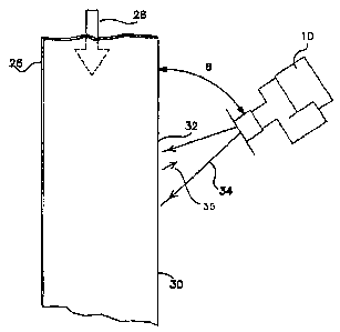
As per Fig.1, A meter (10) is provided for measuring a velocity of a metallic
or
polymer strips or bands (30) moving along a straight path (26). The meter (10)
includes an antenna positioned at a location along the path (32) pointing
towards
65 the strip edge at an oblique angle, and a transceiver electrically
connected to the
antenna. The transceiver transmits, in conjunction with the antenna, a field
of
electromagnetic energy of known magnitude and frequency and receives
reflected electromagnetic energy from material (35) crossing the field to
produce
a signal related to the magnitude and the Doppler-shifted frequency of the
70 reflected electromagnetic energy. The meter (10) also includes an amplifier
coupled to the transceiver, a control unit for calibration, and a central
processing
unit. The central processing unit generates an output signal (4-2OmA current
loop
or voltage output) based upon data received from the control unit and a signal
received from the amplifier, that is proportional to the measured strip
velocity.
Explanation of terms:
Antenna - "microwave antenna" device that receives electromagnetic energy
from a transmitter and radiates it onto free space, and/or a device
that receives electromagnetic energy from space and passes it
into receiver. A property of a directional antenna is that the
emmitted energy is radiated predominantly in one direction in form
of a narrow beam, and that it is sensitive to the received energy
only from a certain narrow range of direction. Important property
of antennas is that the receiveing and transmitting characteristics
are almost always identical.

CA 02546634 2006-05-15
3
Backscatter reflection - scattering of an electromagnetic (or other) beam of
90 energy upon a target, in all directions including also a direction
towards the transmitter, in a similar fashion as beam of light
scatters off a matte or rough (unpolished) surface. Part of the
backscatter radiation forms the retrograde reflection.
95 CW Radar - "Continous Wave" radar, usually the synonym for Doppler Radar
Doppler effect - changing (shifting) of the frequency of a beam of wave
(electromagnetic or other) reflected off a moving target, or
changing (shifting) of wave frequency emitted by a moving
100 tranmitter. The magnitude of the frequency shift is proportional to
the velocity and to the cosine of the angle formed between the
velocity vector and the beam. Doppler effect of electromagnetic
radiation vanishes in case of "Equal angle reflection" (see above)
or when the incident angle equals 90 degree.
105
Doppler Radar - Radar device utilizing Doppler effect principle for measuring
velocity of a moving target. Doppler radars use CW (Continuous
Wave) transceiver for at least part of the measurement cycle,
which extracts the doppler shift by combining (mixing) the
110 transmitted wave with the received wave. The microwave mixer
or detector contained in a receiver, naturally outputs the sum
frequency (which is discarded) and the difference frequency which
is then amplified and measured. The difference frequency is
proportional to the velocity of the target.
115
Detector - "microwave detector" - electronic component sensitive to weak
microwave radiation used for converting such radiation into
electrical signal.
120 Equal angle reflection - reflection of a beam off a target at an agle
equal to the
incidence angle, in a similar fashion as a beam of light reflects off
a mirror.
Microwaves - an arbitrarily selected portion of the electromagnetic energy
125 spectrum with the wavelength between decimeters and one-tenth
of millimeter. Note: some sources may specify slightly different
boundaries, the differences in this terminology are of no practical
importance.
130 Mixer - non-linear component that mixes two signal producing signals that
have frequency equal to the sum and/or to the difference of input

CA 02546634 2006-05-15
4
signals. In the case of radar devices, mixer produces the low
frequency signal of the frequency equal to the difference between
the original transmitter frequency and the received Frequency.
135 The received frequency may be shifted due to reflection off a
moving target (CW Doppler radars), or due to the radar-target-
radar round-trip delay when the transmitter frequency is varied in
time.
140 Receiver - "microwave receiver" - a device that receives incomming
microwave radiation and converts it into other form of electrical
signals , usually of much lower frequency.
145 Retrograde reflection - reflection of the electromagnetic (or other) beam
of
energy off a target, propagating back towards the emitter
(transmitter, tranceiver) along the direction of the original
transmitted beam.
150 Transceiver - transmitter combined with a receiver in one integrated unit.
Transmitter - "microwave transmitter" - device that generates and emmits
microwave energy.
155

Representative Drawing
A single figure which represents the drawing illustrating the invention.
Administrative Status

2024-08-01:As part of the Next Generation Patents (NGP) transition, the Canadian Patents Database (CPD) now contains a more detailed Event History, which replicates the Event Log of our new back-office solution.

Please note that "Inactive:" events refers to events no longer in use in our new back-office solution.

For a clearer understanding of the status of the application/patent presented on this page, the site Disclaimer , as well as the definitions for Patent , Event History , Maintenance Fee  and Payment History  should be consulted.

Event History

Description Date
Time Limit for Reversal Expired 2011-05-16
Application Not Reinstated by Deadline 2011-05-16
Inactive: Adhoc Request Documented 2011-02-17
Deemed Abandoned - Failure to Respond to Maintenance Fee Notice 2010-05-17
Application Published (Open to Public Inspection) 2007-11-15
Inactive: Cover page published 2007-11-14
Inactive: First IPC assigned 2006-08-20
Inactive: IPC assigned 2006-08-20
Inactive: Office letter 2006-06-20
Filing Requirements Determined Compliant 2006-06-13
Inactive: Filing certificate - No RFE (English) 2006-06-13
Application Received - Regular National 2006-06-13
Small Entity Declaration Determined Compliant 2006-05-15

Abandonment History

Abandonment Date Reason Reinstatement Date
2010-05-17

Maintenance Fee

The last payment was received on 2009-05-11

Note : If the full payment has not been received on or before the date indicated, a further fee may be required which may be one of the following

  • the reinstatement fee;
  • the late payment fee; or
  • additional fee to reverse deemed expiry.

Please refer to the CIPO Patent Fees web page to see all current fee amounts.

Fee History

Fee Type Anniversary Year Due Date Paid Date
Application fee - small 2006-05-15
MF (application, 2nd anniv.) - small 02 2008-05-15 2008-04-28
MF (application, 3rd anniv.) - small 03 2009-05-15 2009-05-11
Owners on Record

Note: Records showing the ownership history in alphabetical order.

Current Owners on Record
STAN BLESZYNSKI
Past Owners on Record
None
Past Owners that do not appear in the "Owners on Record" listing will appear in other documentation within the application.
Documents

To view selected files, please enter reCAPTCHA code :


To view images, click a link in the Document Description column. To download the documents, select one or more checkboxes in the first column and then click the "Download Selected in PDF format (Zip Archive)" or the "Download Selected as Single PDF" button.

List of published and non-published patent-specific documents on the CPD .

If you have any difficulty accessing content, you can call the Client Service Centre at 1-866-997-1936 or send them an e-mail at CIPO Client Service Centre.


Document
Description 
Date
(yyyy-mm-dd) 
Number of pages   Size of Image (KB) 
Abstract 2006-05-15 1 25
Description 2006-05-15 4 187
Claims 2006-05-15 3 109
Drawings 2006-05-15 1 7
Representative drawing 2006-11-27 1 5
Cover Page 2007-11-02 2 41
Filing Certificate (English) 2006-06-13 1 158
Notice: Maintenance Fee Reminder 2008-02-18 1 122
Notice: Maintenance Fee Reminder 2009-02-17 1 120
Notice: Maintenance Fee Reminder 2010-02-16 1 121
Courtesy - Abandonment Letter (Maintenance Fee) 2010-07-12 1 172
Second Notice: Maintenance Fee Reminder 2010-11-16 1 118
Reminder - Request for Examination 2011-01-18 1 117
Notice: Maintenance Fee Reminder 2011-02-16 1 120
Correspondence 2006-06-13 1 14
Fees 2008-04-28 1 47
Fees 2009-05-11 1 53