Language selection

Search

Patent 2546777 Summary

Third-party information liability

Some of the information on this Web page has been provided by external sources. The Government of Canada is not responsible for the accuracy, reliability or currency of the information supplied by external sources. Users wishing to rely upon this information should consult directly with the source of the information. Content provided by external sources is not subject to official languages, privacy and accessibility requirements.

Claims and Abstract availability

Any discrepancies in the text and image of the Claims and Abstract are due to differing posting times. Text of the Claims and Abstract are posted:

  • At the time the application is open to public inspection;
  • At the time of issue of the patent (grant).
(12) Patent: (11) CA 2546777
(54) English Title: ROTARY LEADTHROUGH OF A ROBOT ARM
(54) French Title: PASSAGE ROTATIF D'UN BRAS DE ROBOT
Status: Expired and beyond the Period of Reversal
Bibliographic Data
(51) International Patent Classification (IPC):
  • B25J 17/02 (2006.01)
(72) Inventors :
  • SCHULER, SAMUEL (Switzerland)
  • FILIPPI, MARTINO (Switzerland)
(73) Owners :
  • ROBERT BOSCH GMBH
(71) Applicants :
  • ROBERT BOSCH GMBH (Germany)
(74) Agent: BORDEN LADNER GERVAIS LLP
(74) Associate agent:
(45) Issued: 2012-07-10
(86) PCT Filing Date: 2004-11-19
(87) Open to Public Inspection: 2005-06-16
Examination requested: 2009-11-09
Availability of licence: N/A
Dedicated to the Public: N/A
(25) Language of filing: English

Patent Cooperation Treaty (PCT): Yes
(86) PCT Filing Number: PCT/DE2004/002554
(87) International Publication Number: DE2004002554
(85) National Entry: 2006-05-19

(30) Application Priority Data:
Application No. Country/Territory Date
02050/03 (Switzerland) 2003-12-02

Abstracts

English Abstract


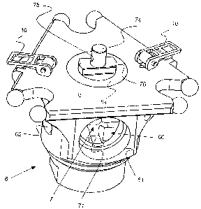
A rotary leadthrough of a robot arm, in particular of a fourth axle of a Delta
robot, has a housing and a shaft, located in an axial leadthrough of the
housing and
supported rotatably in this housing, for connection to the robot arm. The
housing has at
least two openings for cleaning the axial leadthrough. The shaft at least in a
portion of
its length, has a diameter which is less than the diameter of the axial
leadthrough in that
region, so that there is a void between the shaft and the axial leadthrough.


French Abstract

L'invention concerne un passage rotatif (D) d'un bras de robot, notamment d'un quatrième axe (4) d'un robot Delta. Ce passage rotatif comprend un boîtier (6) et un arbre (7), implanté dans un passage axial (60) du boîtier (6) et monté pivotant dans ce boîtier (6), est destiné à être relié au bras de robot (4). Le boîtier (6) comprend au moins deux orifices (61, 62) destinés au nettoyage du passage axial (60). Au moins dans une zone partielle de sa longueur, l'arbre (7) a un diamètre qui est inférieur au diamètre du passage axial (60) dans cette région de telle façon qu'une cavité (R) soit présente entre l'arbre (7) et le passage axial (60).

Claims

Note: Claims are shown in the official language in which they were submitted.


CLAIMS:
1. A rotary leadthrough of a fourth axle of a Delta robot arm, the rotary
leadthrough
comprising:
a housing,
a shaft located in an axial leadthrough of the housing and is rotatably
supported in
the housing, for connection to the robot arm, and
at least two openings in the housing which provide direct access into the
axial
leadthrough from outside the housing for cleaning the axial leadthrough, one
of the at least
two openings being a flushing opening and one of the at least two openings
being a
suction opening, the shaft having a reduced diameter extending over a portion
of its
length, which diameter is less than the diameter of the axial leadthrough in a
corresponding region of the axial leadthrough, thereby providing a void
between the shaft
and the axial leadthrough.
2. The rotary leadthrough in accordance with claim 1, wherein the at least two
openings are located in a radial direction to the axial leadthrough.
3. The rotary leadthrough in accordance with claim 2, wherein the shaft
further
comprises a connection journal on one end, for securing to a joint, and a
securing element,
on a diametrically opposite end, for securing a grasping element.
4. The rotary leadthrough in accordance with claim 3, wherein the securing
element
comprises a star-shaped body portion.
5. The rotary leadthrough in accordance with claim 2, wherein a first of the
at least
two openings is a suction opening, and at least a second of the least two
openings is a
flushing opening, and wherein the suction opening has a larger diameter than
the flushing
opening.
6. The rotary leadthrough in accordance with claim 5, wherein the suction
opening
and the flushing opening are located at an angle of at least approximately
90° to one
another.
6

7. The rotary leadthrough in accordance with claim 1, wherein the void is an
annular
gap.
8. The rotary leadthrough in accordance with claim 1, wherein the shaft
further
comprises a connection journal on one end, for securing to a joint, and a
securing element,
on a diametrically opposite end, for securing a grasping element.
9. The rotary leadthrough in accordance with claim 8, wherein the securing
element
comprises a star-shaped body portion.
10. The rotary leadthrough in accordance claim 1, wherein the housing is made
of
plastic or the shaft is made from an aluminum alloy.
11. A rotary leadthrough of a fourth axle of a Delta robot arm, the rotary
leadthrough
comprising
a housing,
a shaft located in an axial leadthrough of the housing and is rotatably
supported in
that housing, for connection to the robot arm, and at least one opening in the
housing for
cleaning the axial leadthrough, the shaft having a reduced diameter extending
over a
portion of its length, which diameter is less than the diameter of the axial
leadthrough in a
corresponding region of the axial leadthrough, thereby providing a void
between the shaft
and the axial leadthrough, wherein the housing comprises a cylindrical
securing ring,
which on at least one side has a radial groove; wherein the shaft comprises an
annular
groove, which is aligned with the at least one radial groove in the same
plane; and
wherein the rotary leadthrough comprises at least one disk, which can be
brought
into engagement with one each of the at least one radial groove and the
annular groove for
rotatably supporting the shaft in the housing.
12. The rotary leadthrough in accordance with claim 11, wherein the annular
groove is
located in a cylindrical head portion of the shaft, and wherein the
cylindrical head has an
outer diameter which corresponds to an inner diameter of the securing ring.
13. The rotary leadthrough in accordance with claim 12, wherein the shaft
further
7

comprises a connection journal on one end, for securing to a joint, and a
securing element,
on a diametrically opposite end, for securing a grasping element.
14. The rotary leadthrough in accordance claim 12, wherein the housing is made
of
plastic or the shaft is made from an aluminum alloy.
15. The rotary leadthrough in accordance with claim 11, wherein the shaft
further
comprises a connection journal on one end, for securing to a joint, and a
securing element,
on a diametrically opposite end, for securing a grasping element.
16. The rotary leadthrough in accordance claim 11, wherein the housing is made
of
plastic and/or the shaft is made from an aluminum alloy.
17. The rotary leadthrough in accordance with claim 11, wherein a first of the
at least
two openings is a suction extraction opening, and at least a second of the
least two
openings is an inflation opening, and wherein the suction extraction opening
has a larger
diameter than the inflation opening.
18. The rotary leadthrough in accordance with claim 17, wherein the suction
extraction
opening and the inflation opening are located at an angle of at least
approximately 90° to
one another.
19. A rotary leadthrough of a fourth axle of a Delta robot arm, the rotary
leadthrough
comprising
a housing,
a shaft located in an axial leadthrough of the housing and is rotatably
supported in
that housing, for connection to the robot arm, and at least one opening in the
housing for
cleaning the axial leadthrough, the shaft having a reduced diameter extending
over a
portion of its length, which diameter is less than the diameter of the axial
leadthrough in a
corresponding region of the axial leadthrough, thereby providing a void
between the shaft
and the axial leadthrough, wherein at least two openings are located in a
radial direction to
the axial leadthrough;
8

wherein the housing comprises a cylindrical securing ring, which on at least
one
side has a radial groove;
wherein the shaft comprises an annular groove, which is aligned with the at
least
one radial groove in the same plane; and
wherein the rotary leadthrough comprises at least one disk, which can be
brought
into engagement with one each of the at least one radial groove and the
annular groove for
rotatably supporting the shaft in the housing.
20. The rotary leadthrough in accordance with claim 19, wherein the annular
groove is
located in a cylindrical head portion of the shaft, and wherein the
cylindrical head has an
outer diameter which corresponds to an inner diameter of the securing ring.
9

Description

Note: Descriptions are shown in the official language in which they were submitted.


e CA 02546777 2006-05-19
ROTARY LEADTHROUGH OF A ROBOT ARM
FIELD OF THE INVENTION
The invention relates to a rotary leadthrough of a robot arm, in particular of
a
fourth axle of a Delta robot.
BACKGROUND OF THE INVENTION
Delta robots are known from European Patent Disclosures EP-B 0 250 470, EP-
A 1 129 829, and EP-A 1 293 691. These Delta robots are suitable for moving
objects
precisely and in a guided way in three-dimensional space. They have proven
themselves in practice and are used, among other fields, in the food industry
or in
machining centers that have stringent cleanliness requirements. Cleaning the
rotary
leadthrough of the fourth axle, however, is sometimes complicated. Until now,
this
rotary leadthrough has been embodied such that a hollow shaft was supported in
a
housing, and the shaft had a radial inflation opening in its central void.
Precisely in the aforementioned areas of use, however, it would be desirable
to
be able to clean the entire robot and especially the region of the rotary
leadthrough of
the fourth axle better and more simply.
US Patent 5,775,169 moreover discloses a robot arm that is used for
manipulation in a vacuum chamber, but that is operated from outside. The robot
arm is
rotatably supported in a housing, and there is a seal in the housing, for
dividing the part
of the robot arm toward the vacuum from the part toward the atmosphere.
It is therefore an object of the invention to create a rotary leadthrough for
a robot
arm, in particular for a fourth axle of a Delta robot, which is constructed
simply and is
less vulnerable to soiling and which makes good cleaning possible.
SUMMARY OF THE INVENTION
The rotary leadthrough of the invention has a housing and a shaft, located in
an
axial leadthrough of the housing and supported rotatably in this housing, for
connection
to the robot arm. The housing has at least two openings for cleaning the axial
leadthrough. The shaft, at least in a portion of its length, has a diameter
which is less
than the diameter of the axial leadthrough in that region, so that there is a
void, in
1

CA 02546777 2006-05-19
particular an annular gap that is open in at least one direction, between the
shaft and the
axial leadthrough.
The rotary leadthrough can therefore be cleaned easily and without tedious
disassembly, by means of a fluid medium, such as water or compressed air.
Furthermore, because of its construction, the rotary leadthrough is less
vulnerable to
soiling. The rotary leadthrough requires relatively few individual parts,
making it
economical to manufacture and easy to assemble. A further advantage is that
the rotary
leadthrough can be put together and also secured to the robot without
auxiliary tools.
A further advantage is that the shaft can be made relatively slender; that the
housing is hollow; and that these parts can be made of lightweight materials.
This
optimizes the moment of mass inertia of the fourth axle or of the robot arm.
This effect
is reinforced by the fact that the mass of the shaft is concentrated about the
central axis
of rotation, and not spaced apart from it as in the prior art.
BRIEF DESCRIPTION OF THE DRAWINGS
The subject of the invention is described below in terms of a preferred
exemplary embodiment, which is shown in the accompanying drawings, in which
Fig. 1, is a perspective view of a conventional Delta robot;
Fig. 2, is a perspective view of a rotary leadthrough of the invention,
secured to
a carrier plate;
Fig. 3, is a perspective view of a shaft of the rotary leadthrough of Fig. 2;
Fig. 4, is a top plan view of the rotary leadthrough with the carrier plate of
Fig. 2
from below;
Fig. 5, is a first longitudinal section through the rotary leadthrough with
the
carrier plate of Fig. 2;
Fig. 6, is a second longitudinal section through the rotary leadthrough with
the
carrier plate of Fig. 2; and
Fig. 7, is a third longitudinal section through the rotary leadthrough with
the
carrier plate of Fig. 2.
DESCRIPTION OF THE PREFERRED EMBODIMENTS
Except for the rotary leadthrough D described hereinafter, the Delta robot
shown
2

CA 02546777 2006-05-19
in Fig. 1 is equivalent to the known Delta robots and has a platelike basic
element 1, on
which three control arms 3 are supported so as to be pivotable or rotatable.
The three
control arms 3 can be moved individually by means of motors 2. The free ends
of the
control arms 3 are pivotably connected to a carrier element, in this case a
carrier plate 5.
The Delta robot also has a fourth axle 4, which is often telescoping or
otherwise
changeable in length. This fourth axle 4 is connected to the rotary
leadthrough D via a
joint 9, in particular a cardan joint or a universal joint. A grasping
element, not shown,
can be secured to the rotary leadthrough D on the side of the rotary
leadthrough D
diametrically opposite the fourth axle 4. The type of grasping element depends
on the
field in which it is to be used. Examples of grasping elements are suction
cups or
clamping means. By means of the three control arms 3, the carrier plate 5 and
thus the
grasping element can be moved in three-dimensional space. The fourth axle 4
transmits
a torque to the grasping element, so that the grasping element can furthermore
be rotated
purposefully about an axis.
In Fig. 2, a rotary leadthrough according to the invention is shown, secured
to
the carrier plate 5. This view is on a larger scale; the size of the rotary
leadthrough can
be selected to suit the size of the robot and the field of use, without
altering the concept
of the invention.
The rotary leadthrough has a housing 6 with an axial leadthrough 60. According
to the invention, at least one opening, and here precisely two openings 61,62
are present,
which create a connection from the outside to the axial leadthrough 60 and are
preferably located in the radial direction to the axial leadthrough.
The housing 6 has a securing ring 64, which is received in an opening in the
carrier plate 5. The outer diameter of the securing ring 64 is preferably
equivalent to the
inner diameter of the opening in the carrier plate 5.
The housing 6 can be secured to the carrier plate 5 by means of clamps 10.
Alternatively or in addition, connections by means of screws 11 are also
possible, as can
be seen in Figs. 5 and 7. For receiving the screws 11 and for securing the
clamps 10, the
housing 6 has a securing flange 63 (Figs. 5 and 7), which protrudes past the
substantially cylindrical basic body of the housing 6. Securing by means of
clamps 10
has the advantage that the rotary leadthrough D can be removed in a simple
way, and
without auxiliary tools.
3

CA 02546777 2006-05-19
The basic body of the housing 6 may also take some other form. The form
depends essentially on the field of use. Preferably, the housing 6 is made
from plastic,
so that it has a relatively low weight and assures good sliding behaviour of
the shaft in
the housing.
A shaft 7 is rotatably supported in the housing 6 and is located in and
penetrates
the axial leadthrough 60. This shaft serves on the one hand to provide
connection to the
fourth axle 4 and on the other to provide connection to the grasping element.
As can be
seen from Fig. 2, shaft 7 protrudes out of the leadthrough 60 with a sliding
block 76 and
a connection journal 74 on the side toward the carrier plate 5 and also
protudes passed
the carrier plate 5. Via the sliding block 76, a groove of the universal joint
9 can be
displaced, causing the connection journal 74 to protrude into the universal
joint 9. The
fixation of this connection is done by means of a bolt or pin, which is passed
through a
bore in the universal joint 9 and through a bore 75, aligned with it, of the
connection
journal 74. Preferably, an anchor-shaped fixation means, not shown here, is
used, which
has a resilient curved element and a pin located on the curved element. The
curved
element can be fitted resiliently over the cylindrical body of the universal
joint,
whereupon the pin penetrates the bores.
The shaft 7 is shown by itself in Fig. 3. It is preferably made from a
lightweight
material, such as an aluminum alloy. It has an axle 70, which on one end
merges with a
cylindrical head 72 that has an adjoining journal74 and on the other end with
a star-
shaped securing element 71. As a result, as can be seen best from Figs. 5
through 7, the
shaft, over at least a portion of its length, namely the length of its axle
70, has an outer
diameter that is smaller than the inner diameter of the axial leadthrough 60.
This creates
a void, embodied as an annular gap R (see Figs. 5 through 7), into which the
aforementioned radial leadthrough openings 61,62 lead.
The cylindrical head 72 of the shaft 7 has an encompassing annular groove 73
below the sliding block 76. By means of this annular groove 73, the shaft 7
can be
axially supported rotatably in the housing 6. For that purpose, in its
securing ring 64, the
housing 6 has at least one and in this case two diametrically opposed circular-
segment-
shaped grooves 65. The cylindrical head 72, in the assemble state, is
introduced into an
opening in the securing ring 64, in which it is preferably received without
play, and its
outward-oriented surface is also aligned with the surface of the securing ring
64. In this
state, the circular-segment-shaped grooves 65 and the annular groove 73 are in
the same
4

CA 02546777 2006-05-19
plane with one another. The axial position of the shaft 7 can now be fixed by
thrusting
segmental disks 66, preferably also made of plastic, into the circular-segment-
shaped
grooves 65 until they engage the annular groove 73. This can be seen best in
Figs. 5
through 7. In the installed state of the housing 6 in the carrier plate 5, the
segmental
disks 66 rest on the side walls of the opening in the carrier plate 5 and are
thus secured
by it.
An intermediate member 8, which is joined to the star body 71 of the shaft 7,
is
also visible in these drawings. The shape of the intermediate member depends
on the
type of grasping element used. Preferably, however, it also has an axial
through
opening 80, so that the annular gap R has a connection to the outside in this
direction.
This can be best seen in Fig. 4. The star body 71 has the advantage that,
while it makes
sufficient stability and simple securing possible, nevertheless it reduces the
inside cross
section as little as possible.
The aforementioned radial openings now enable simple cleaning of the rotary
leadthrough D, and in particular of the annular gap R, by means of a fluid
medium, such
as water, a cleaning solution, or compressed air. A first one of the openings
61 is a
suction extraction opening, and a second opening 62 is an inflation or
flushing opening.
Preferably, the suction extraction opening 61 has a larger diameter than the
inflation
opening 62. Preferably, the two openings 61,62 are also disposed at an angle
of at least
approximately 90 to one another. They may be located at the same height or at
different
heights.
The rotary leadthrough of the invention finds its preferred field of use, as
described above, upon the leadthrough of a fourth axle of a Delta robot or
similar robot.
However, its use with robot arms of robots of other designs is also possible
and is also
part of the concept of the invention.
The foregoing relates to preferred exemplary embodiments of the invention, it
being understood that other variants and embodiments thereof are possible
within the
spirit and scope of the invention, the latter being defined by the appended
claims.
5

Representative Drawing
A single figure which represents the drawing illustrating the invention.
Administrative Status

2024-08-01:As part of the Next Generation Patents (NGP) transition, the Canadian Patents Database (CPD) now contains a more detailed Event History, which replicates the Event Log of our new back-office solution.

Please note that "Inactive:" events refers to events no longer in use in our new back-office solution.

For a clearer understanding of the status of the application/patent presented on this page, the site Disclaimer , as well as the definitions for Patent , Event History , Maintenance Fee  and Payment History  should be consulted.

Event History

Description Date
Time Limit for Reversal Expired 2016-11-21
Letter Sent 2015-11-19
Letter Sent 2013-03-12
Inactive: Correspondence - MF 2013-02-15
Inactive: Office letter 2013-01-29
Grant by Issuance 2012-07-10
Inactive: Cover page published 2012-07-09
Pre-grant 2012-05-02
Inactive: Final fee received 2012-05-02
Notice of Allowance is Issued 2011-12-02
Letter Sent 2011-12-02
Notice of Allowance is Issued 2011-12-02
Inactive: Approved for allowance (AFA) 2011-11-29
Amendment Received - Voluntary Amendment 2011-08-16
Inactive: S.30(2) Rules - Examiner requisition 2011-02-18
Letter Sent 2010-01-05
Request for Examination Requirements Determined Compliant 2009-11-09
All Requirements for Examination Determined Compliant 2009-11-09
Request for Examination Received 2009-11-09
Letter Sent 2007-06-27
Inactive: Correspondence - Transfer 2007-05-29
Inactive: Single transfer 2007-05-16
Inactive: Cover page published 2006-08-07
Inactive: Courtesy letter - Evidence 2006-08-01
Inactive: Notice - National entry - No RFE 2006-07-28
Application Received - PCT 2006-06-14
National Entry Requirements Determined Compliant 2006-05-19
Amendment Received - Voluntary Amendment 2006-05-19
Application Published (Open to Public Inspection) 2005-06-16

Abandonment History

There is no abandonment history.

Maintenance Fee

The last payment was received on 2011-11-08

Note : If the full payment has not been received on or before the date indicated, a further fee may be required which may be one of the following

  • the reinstatement fee;
  • the late payment fee; or
  • additional fee to reverse deemed expiry.

Patent fees are adjusted on the 1st of January every year. The amounts above are the current amounts if received by December 31 of the current year.
Please refer to the CIPO Patent Fees web page to see all current fee amounts.

Owners on Record

Note: Records showing the ownership history in alphabetical order.

Current Owners on Record
ROBERT BOSCH GMBH
Past Owners on Record
MARTINO FILIPPI
SAMUEL SCHULER
Past Owners that do not appear in the "Owners on Record" listing will appear in other documentation within the application.
Documents

To view selected files, please enter reCAPTCHA code :


To view images, click a link in the Document Description column (Temporarily unavailable). To download the documents, select one or more checkboxes in the first column and then click the "Download Selected in PDF format (Zip Archive)" or the "Download Selected as Single PDF" button.

List of published and non-published patent-specific documents on the CPD .

If you have any difficulty accessing content, you can call the Client Service Centre at 1-866-997-1936 or send them an e-mail at CIPO Client Service Centre.

({010=All Documents, 020=As Filed, 030=As Open to Public Inspection, 040=At Issuance, 050=Examination, 060=Incoming Correspondence, 070=Miscellaneous, 080=Outgoing Correspondence, 090=Payment})


Document
Description 
Date
(yyyy-mm-dd) 
Number of pages   Size of Image (KB) 
Drawings 2006-05-18 5 120
Claims 2006-05-18 3 68
Description 2006-05-18 10 280
Abstract 2006-05-18 1 15
Representative drawing 2006-08-01 1 14
Description 2006-05-19 5 256
Abstract 2006-05-19 1 13
Claims 2006-05-19 3 117
Drawings 2006-05-19 5 118
Claims 2011-08-15 4 153
Reminder of maintenance fee due 2006-07-30 1 110
Notice of National Entry 2006-07-27 1 193
Request for evidence or missing transfer 2007-05-22 1 102
Courtesy - Certificate of registration (related document(s)) 2007-06-26 1 107
Reminder - Request for Examination 2009-07-20 1 116
Acknowledgement of Request for Examination 2010-01-04 1 188
Commissioner's Notice - Application Found Allowable 2011-12-01 1 163
Maintenance Fee Notice 2015-12-30 1 171
PCT 2006-05-18 5 177
Correspondence 2006-07-27 1 27
Correspondence 2012-05-01 1 31
Correspondence 2013-01-28 1 15
Correspondence 2013-02-14 2 89
Correspondence 2013-03-11 1 13