Language selection

Search

Patent 2547071 Summary

Third-party information liability

Some of the information on this Web page has been provided by external sources. The Government of Canada is not responsible for the accuracy, reliability or currency of the information supplied by external sources. Users wishing to rely upon this information should consult directly with the source of the information. Content provided by external sources is not subject to official languages, privacy and accessibility requirements.

Claims and Abstract availability

Any discrepancies in the text and image of the Claims and Abstract are due to differing posting times. Text of the Claims and Abstract are posted:

  • At the time the application is open to public inspection;
  • At the time of issue of the patent (grant).
(12) Patent: (11) CA 2547071
(54) English Title: SCREW FEEDER ADAPTER FOR A POWER SCREWDRIVER
(54) French Title: ADAPTATEUR DE DISTRIBUTEUR A VIS POUR TOURNEVIS ELECTRIQUE
Status: Expired and beyond the Period of Reversal
Bibliographic Data
(51) International Patent Classification (IPC):
  • B25B 23/04 (2006.01)
(72) Inventors :
  • HSU, MING-HUNG (Taiwan, Province of China)
(73) Owners :
  • MOBILETRON ELECTRONICS CO., LTD.
(71) Applicants :
  • MOBILETRON ELECTRONICS CO., LTD. (Taiwan, Province of China)
(74) Agent: OSLER, HOSKIN & HARCOURT LLP
(74) Associate agent:
(45) Issued: 2009-07-21
(22) Filed Date: 2006-05-16
(41) Open to Public Inspection: 2007-03-06
Examination requested: 2006-05-16
Availability of licence: N/A
Dedicated to the Public: N/A
(25) Language of filing: English

Patent Cooperation Treaty (PCT): No

(30) Application Priority Data:
Application No. Country/Territory Date
94215338 (Taiwan, Province of China) 2005-09-06

Abstracts

English Abstract

A screw feeder adapter includes a housing having a first connecting portion for connection to a screw feeder, a second connecting portion, and a retaining portion connected between the first connecting portion and the second connecting portion, a coupling member connectable to a power screwdriver and coupled to the second connecting portion of the housing through a rotary motion, and two locking units respectively pivoted to the retaining portion of the housing at two sides and forced by a respective spring member to engage into a respective retaining hole at the housing and a respective retaining groove at the coupling member to lock the coupling member to the housing.


French Abstract

Adaptateur pour distributeur à vis comprenant un boîtier doté d'une première partie de connexion pour le raccordement à un distributeur à vis, une seconde partie de connexion, une partie de retenue entre la première partie de connexion et la seconde partie de connexion, un élément de couplage pouvant être raccordé à un tournevis électrique et couplé à la seconde partie de connexion du boîtier par un mouvement rotatif, deux éléments de verrouillage, tous les deux étant fixés de façon pivotante à la partie de retenue du boîtier sur les deux côtés et retenus en place par un ressort respectif afin de permettre un enclenchement dans un trou de retenue respectif sur le boîtier, et une rainure de retenue respective à chacun des éléments sur l'élément de couplage pour permettre le verrouillage de l'élément de couplage au boîtier.

Claims

Note: Claims are shown in the official language in which they were submitted.

WHAT IS CLAIMED IS:
1. A screw feeder adapter for detachably connecting a screw feeder to a
power screwdriver, the screw feeder adapter comprising:
a housing having a first connecting portion for connecting to the screw
feeder, a second connecting portion, a retaining portion connected between
said first
connecting portion and said second connecting portion, a receiving open
chamber
axially extending through said first connecting portion, said retaining
portion and said
second connecting portion, two retaining holes respectively formed in said
retaining
portion at two opposite lateral sides in communication with said receiving
open
chamber, and two inside locating blocks respectively projecting from an inside
wall of
said second connecting portion;
a coupling member for connecting the second connecting portion of said
housing to the power screwdriver, said coupling member having two locating
structures disposed at two opposite lateral sides for coupling to the inside
locating
blocks of said housing, and two retaining grooves respectively disposed
adjacent to
said locating structures; and
two locking units respectively pivotally coupled to said retaining portion of
said housing and engageable into said retaining holes of said housing and said
retaining grooves of said coupling member to lock said coupling member to said
housing.
2. The screw feeder adapter as claimed in claim 1, wherein said housing
comprises a plurality of lock holes formed in said first connecting portion
for receiving
a respective spring pin of a screw feeder to be attached to said first
connecting portion
7

of said housing.
3. The screw feeder adapter as claimed in claim 1, wherein said housing
comprises a plurality of coupling grooves respectively formed in an outside
wall of
said retaining portion above said retaining holes; said locking units each
comprise a
connecting portion respectively pivotally coupled to the coupling grooves of
said
housing.
4. The screw feeder adapter as claimed in claim l, wherein said housing
comprises two bearing portions respectively provided outside said retaining
portion at
two opposite lateral sides; said locking units each comprise a locking member
respectively pivotally coupled to said retaining portion of said housing and
turnable
relative to said housing between a locking position to lock said coupling
member to
said housing and an unlocking position for disconnection of said coupling
member
from said housing, and a spring member coupled to one of said bearing portions
of said
housing and stopped between said retaining portion of said housing and said
locking
member to hold said locking member in said locking position.
5. The screw feeder adapter as claimed in claim 4, wherein said locking
member comprises a handle disposed at one end thereof for pressing by the
user, a
locking tip disposed at an opposite end thereof for engaging into one
retaining hole of
said housing and one retaining groove of said coupling member to lock said
coupling
member to said housing, and a connecting portion spaced between said handle
and said
locking tip and pivoted to said retaining portion of said housing.
6. The screw feeder adapter as claimed in claim 1, wherein the spring
8

member of each of said two locking units is a curved spring plate.
7. The screw feeder adapter as claimed in claim 1, wherein said coupling
member has a coupling hole for coupling to a power screwdriver.
8. The screw feeder adapter as claimed in claim 1, wherein said locating
structures of said coupling member each comprise a guide groove, which extends
axially from one end of said coupling member, and a positioning groove
extending
from one end of said guide groove for receiving one of said locating blocks of
said
housing to prohibit axial displacement of said housing relative to said
coupling
member after insertion of said locating blocks of said housing into the guide
grooves of
said locating structure and after a rotary motion of said housing relative to
said
coupling member.
9

Description

Note: Descriptions are shown in the official language in which they were submitted.


CA 02547071 2006-05-16
SCREW FEEDER ADAPTER FOR A POWER SCREWDRIVER
BACKGROUND OF THE INVENTION
1. Field of the Invention
The present invention relates to power hand tools and more particularly, to a
screw feeder adapter for detachably connecting a screw feeder to a power
screwdriver.
2. Description of the Related Art
When proceeding with a screw fastening or unfastening task, a manual
screwdriver or a power screwdriver may be used. Further, when performing a
task that
requires installation of a big amount of screws, a screw feeder or screw
magazine may
be used with a power screwdriver so that screws can be automatically fed into
the
power screwdriver and quickly driven into the workpiece with the power
screwdriver.
According to a conventional design, the connection between a screw feeder and
a
power screwdriver is done through a lock nut. However, it takes much time to
connect
the screw feeder to the power screwdriver with the lock nut and to rotate the
lock nut
to the locking position. When wishing to detach the screw feeder from the
power
screwdriver, it also takes much time to rotate the lock nut from the locking
position to
the unlocking position and then to disconnect the screw feeder and the lock
nut from
the power screwdriver.
SUMMARY OF THE INVENTION
The present invention has been accomplished under the circumstances in
view. It is therefore one object of the present invention to provide a screw
feeder
adapter, which can quickly and detachably be installed to connect a screw
feeder to a
power screwdriver.
To achieve this object of the present invention, the screw feeder adapter for

CA 02547071 2006-05-16
detachably connecting a screw feeder to a power screwdriver comprises a
housing, a
coupling member, and two locking units. The housing has a first connecting
portion for
connecting to the screw feeder, a second connecting portion, a retaining
portion
connected between the first connecting portion and the second connecting
portion, a
receiving open chamber axially extending through the first connecting portion,
the
retaining portion and the second connecting portion, two retaining holes
respectively
formed in the retaining portion at two opposite lateral sides in communication
with the
receiving open chamber, and two inside locating blocks respectively projecting
from
an inside wall of the second connecting portion. The coupling member is
connected
the second connecting portion of the housing to the power screwdriver. The
coupling
member has two locating structures disposed at two opposite lateral sides
thereof for
coupling to the inside locating blocks of said housing, and two retaining
grooves
respectively disposed adjacent to the locating structures. The locking units
are
respectively pivotally coupled to the retaining portion of the housing and
engageable
into the retaining holes of the housing and the retaining grooves of the
coupling
member to lock the coupling member to the housing.
BRIEF DESCRIPTION OF THE DRAWINGS
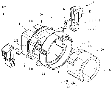
FIG 1 is an exploded view of a screw feeder adapter for a power screwdriver
according to a preferred embodiment of the present invention.
FIG 2 is a perspective assembly view of the screw feeder adapter according
to the preferred embodiment of the present invention.
FIG. 3 is a schematic drawing showing the invention in use.
FIG. 4 is a sectional view of the present invention, showing the screw feeder
adapter locked.
FIG. 5 is a sectional view of the present invention, showing the screw feeder

CA 02547071 2006-05-16
adapter unlocked.
FIG. 6 is a sectional view of the present invention, showing the detachable
status of the screw feeder adapter.
DETAILED DESCRIPTION OF THE INVENTION
Referring to FIGS. 1 and 2, a screw feeder adapter 100 in accordance with
the preferred embodiment of the present invention is shown comprising a
housing 10, a
coupling 20, and two locking units 30.
The housing 10 is made in integrity, having a first connecting portion 11, a
retaining portion 12 and a second connecting portion 13. The retaining portion
12 has
two ends respectively connected to the first connecting portion 11 and the
second
connecting portion 12, i.e., the retaining portion 12 is disposed between the
first
connecting portion 11 and the second connecting portion 13. The first
connecting
portion 11, the second connecting portion 13 and the retaining portion 12
define an
axially extending receiving open chamber 14, i.e., the receiving open chamber
14
extends through the free ends of the first connecting portion 11 and second
connecting
portion 13 in communication with the outside of the housing 10.
The first connecting portion 11 is a hollow rectangular structure surrounding
the receiving open chamber 14, having a plurality of lock holes 111 in the
peripheral
wall thereof.
The retaining portion 12 is a hollow member surrounding the receiving open
chamber 14 and connected between the first connecting portion 11 and the
second
connecting portion 13, having a retaining hole 121 disposed at each of the two
opposite
lateral sides thereof, two coupling grooves 122 disposed at each of the two
opposite
lateral sides above the retaining hole 121, and a bearing member (for example,
a
2~ suspension rod) 123 disposed at each of the two opposite lateral sides
right above the
3

CA 02547071 2006-05-16
respective retaining hole 121 and spaced between the respective coupling
grooves 122.
The second connecting portion 13 has a circular cross section surround the
receiving open chamber 14 and is connected to one end of the retaining portion
12
opposite to the first connecting portion 11. Further, the second connecting
portion 13
has two locating blocks 131 bilaterally protruding from the inside wall.
The coupling member 20 is shaped like a barrel defining an axially extending
coupling hole 21, having two substantially L-shaped locating structures 22
symmetrically disposed on the outside wall at two opposite lateral sides. Each
locating
structure 22 comprises a guide groove 221, which extends axially from one end
of the
outside wall of the coupling member 20, and a positioning groove 222
perpendicularly
extending from one end of the guide groove 221. The coupling member 20 further
has
two retaining grooves 223 respectively formed on the outside wall thereof
adjacent to
the guide grooves 221 of the locating structure 22 respectively.
The locking units 30 each are comprised of a locking member 31 and a
spring member 32. The locking member 31 is pivotally connected to the housing
10
and turnable relative to the housing 10 between a locking position and an
unlocking
position. The locking member 31 has a handle 311 at one end, a locking tip 312
at the
other end, and a connecting portion, for example, a pivot rod 313 on the
middle
between the handle 311 and the locking tip 312. The handle 311 and the locking
tip
312 respectively extend from the two distal ends of the locking member 31 in
reversed
directions.
The assembly process of the screw feeder adapter 100 is simple and outlined
hereinafter with reference to FIGS. 1 and 2 again. The spring members 32 of
the two
locking units 30 are curved spring plates respectively inserted through the
gaps
between the peripheral wall of the retaining portion 12 and the bearing
members 123
y

CA 02547071 2006-05-16
and attached to the periphery of the bearing members 123, and then the pivot
rods 313
of the locking members 31 are respectively pivotally coupled to the coupling
grooves
122 of the retaining portion 12 to have the two distal ends of each of the
spring
members 32 be respectively stopped against the outside wall of the retaining
portion 12
of the housing 10 and the inside wall of each of the locking members 31. By
means of
the spring force of the spring members 32, the locking members 31 are held in
the
locking position where the locking tips 312 of the locking members 31 are
respectively
inserted through the retaining holes 121 into the receiving open chamber 14.
The use of the present invention is outlined hereinafter with reference to
FIGS. 3 and 4 and FIGS. 1 and 2 again. The coupling hole 21 of the coupling
member
is press-fitted onto the coupling end 41 of the power screwdriver 40, and then
the
coupling member 20 is inserted into the receiving open chamber 14 within the
second
connecting portion 13 for enabling the locating blocks 131 of the second
connecting
portion 13 to be respectively inserted into the guide grooves 221 of the
locating
15 structures 22 of the coupling member 20, and then the housing 10 and the
coupling
member 20 are rotated relative to each other through an angle to move the
locating
blocks 131 into the positioning grooves 222 of the locating structures 22
respectively
to further prohibit relative movement in axial direction between the housing
10 and the
coupling member 20. At this time, the retaining grooves 223 of the coupling
member
20 20 are forced into engagement with the locking tips 312 of the locking
members 31,
and therefore the locking members 31 lock the coupling member 20 to the
housing 10.
Thereafter, the first connecting portion 11 of the housing 10 is inserted into
the
coupling end 51 of the screw feeder 50. Upon insertion of the first connecting
portion
11 of the housing 10 to the coupling end 51 of the screw feeder 50, the spring
pins ~2
of the screw feeder 50 automatically engage into the lock holes 111 to lock
the screw

CA 02547071 2006-05-16
feeder 50 to the housing 10. Thus, the screw feeder adapter 100 connects the
screw
feeder 50 to the power screwdriver 40.
When wishing to detach the screw feeder adapter 100 from the screw feeder
50 and the power screwdriver 40, press the handles 311 of the locking members
31 to
bias the locking members 31 relative to the housing 10 and to move the locking
members 31 from the locking position to the unlocking position where the
locking tips
312 are respectively disengaged from the respective retaining grooves 223 (see
FIG. 5),
and then rotate the coupling member 20 relative to the housing 10 in the
reversed
direction to move the locating blocks 131 out of the respective positioning
grooves 222
into the respective guide grooves 221. At this time, the coupling member 20 is
unlocked from the housing 10 and can be detached with the power screwdriver 40
from
the housing 10. Thereafter, the housing 10 can be disconnected from the
coupling end
51 of the screw feeder 50, and the coupling member 20 can be detached from the
coupling end 41 of the power screwdriver 41.
In the aforesaid embodiment, the coupling member is an independent
member. Alternatively, the coupling member can be formed integral with one end
of
the power screwdriver.
Although a particular embodiment of the invention has been described in
detail for purposes of illustration, various modifications and enhancements
may be
made without departing from the spirit and scope of the invention.
Accordingly, the
invention is not to be limited except as by the appended claims.
6

Representative Drawing
A single figure which represents the drawing illustrating the invention.
Administrative Status

2024-08-01:As part of the Next Generation Patents (NGP) transition, the Canadian Patents Database (CPD) now contains a more detailed Event History, which replicates the Event Log of our new back-office solution.

Please note that "Inactive:" events refers to events no longer in use in our new back-office solution.

For a clearer understanding of the status of the application/patent presented on this page, the site Disclaimer , as well as the definitions for Patent , Event History , Maintenance Fee  and Payment History  should be consulted.

Event History

Description Date
Time Limit for Reversal Expired 2014-05-16
Letter Sent 2013-05-16
Grant by Issuance 2009-07-21
Inactive: Cover page published 2009-07-20
Inactive: Final fee received 2009-04-08
Pre-grant 2009-04-08
Notice of Allowance is Issued 2008-10-09
Letter Sent 2008-10-09
Notice of Allowance is Issued 2008-10-09
Inactive: Approved for allowance (AFA) 2008-09-12
Application Published (Open to Public Inspection) 2007-03-06
Inactive: Cover page published 2007-03-05
Inactive: IPC assigned 2006-11-01
Inactive: First IPC assigned 2006-11-01
Letter Sent 2006-06-16
Inactive: Filing certificate - RFE (English) 2006-06-16
Application Received - Regular National 2006-06-16
Correct Applicant Requirements Determined Compliant 2006-06-16
Filing Requirements Determined Compliant 2006-06-16
Letter Sent 2006-06-16
Request for Examination Requirements Determined Compliant 2006-05-16
All Requirements for Examination Determined Compliant 2006-05-16

Abandonment History

There is no abandonment history.

Maintenance Fee

The last payment was received on 2009-05-04

Note : If the full payment has not been received on or before the date indicated, a further fee may be required which may be one of the following

  • the reinstatement fee;
  • the late payment fee; or
  • additional fee to reverse deemed expiry.

Please refer to the CIPO Patent Fees web page to see all current fee amounts.

Fee History

Fee Type Anniversary Year Due Date Paid Date
Application fee - standard 2006-05-16
Request for examination - standard 2006-05-16
Registration of a document 2006-05-16
MF (application, 2nd anniv.) - standard 02 2008-05-16 2008-05-08
Final fee - standard 2009-04-08
MF (application, 3rd anniv.) - standard 03 2009-05-19 2009-05-04
MF (patent, 4th anniv.) - standard 2010-05-17 2010-05-17
MF (patent, 5th anniv.) - standard 2011-05-16 2011-05-09
MF (patent, 6th anniv.) - standard 2012-05-16 2012-05-03
Owners on Record

Note: Records showing the ownership history in alphabetical order.

Current Owners on Record
MOBILETRON ELECTRONICS CO., LTD.
Past Owners on Record
MING-HUNG HSU
Past Owners that do not appear in the "Owners on Record" listing will appear in other documentation within the application.
Documents

To view selected files, please enter reCAPTCHA code :


To view images, click a link in the Document Description column. To download the documents, select one or more checkboxes in the first column and then click the "Download Selected in PDF format (Zip Archive)" or the "Download Selected as Single PDF" button.

List of published and non-published patent-specific documents on the CPD .

If you have any difficulty accessing content, you can call the Client Service Centre at 1-866-997-1936 or send them an e-mail at CIPO Client Service Centre.


Document
Description 
Date
(yyyy-mm-dd) 
Number of pages   Size of Image (KB) 
Abstract 2006-05-16 1 17
Description 2006-05-16 6 245
Claims 2006-05-16 3 93
Drawings 2006-05-16 5 108
Representative drawing 2007-02-14 1 17
Cover Page 2007-02-27 1 46
Cover Page 2009-06-25 2 51
Acknowledgement of Request for Examination 2006-06-16 1 176
Courtesy - Certificate of registration (related document(s)) 2006-06-16 1 105
Filing Certificate (English) 2006-06-16 1 158
Reminder of maintenance fee due 2008-01-17 1 112
Commissioner's Notice - Application Found Allowable 2008-10-09 1 163
Maintenance Fee Notice 2013-06-27 1 170
Fees 2008-05-08 1 56
Correspondence 2009-04-08 1 49
Fees 2009-05-04 1 48
Fees 2010-05-17 1 46
Fees 2011-05-09 1 53
Fees 2012-05-03 1 48