Note: Descriptions are shown in the official language in which they were submitted.
CA 02547957 2006-06-02
METHOD AND ROLL STAND FOR MULTIPLY
INFLUENCING PROFILES
The invention concerns a method and a rolling stand for
rolling plate or strip, with work rolls supported on backup
rolls or on intermediate rolls with backup rolls, wherein the
adjustment of the roll gap profile is carried out by axial
shifting of pairs of rolls provided with curved contours. The
rolls of selected roll pairs can be shifted axially relative to
each other in pairs, and each roll of such a roll pair is
provided with a curved profile, which extends towards opposite
sides on both rolls of the roll pair over the entire length of
the roll barrel. Well-known embodiments are four-high mills,
six-high mills, and the various forms of cluster mills
configured as one-way mills, reversing mills, or tandem mills.
In the hot rolling of small final thicknesses and in cold
rolling, it is necessary to deal with the problem of maintaining
flatness by countering two fundamentally different causes of
off-flatness with the same adjusting means:
1
CA 02547957 2006-06-02
-- The desired profile of the rolling stock, i.e., the
distribution of the thickness of the rolling stock over the
width of the rolling stock that is necessary to maintain
flatness, decreases proportionally to the nominal thickness of
the rolling stock from pass to pass. Especially in the case of
one-way mills and reversing mills, the adjusting mechanisms must
be capable of realizing the appropriate adjustments.
-- Depending on the current rolling force, the roll
temperature and the state of wear of the rolls, the profile
height and profile distribution to be compensated with the
adjusting mechanisms change from pass to pass. The adjusting
mechanisms must be able to compensate the changes in profile
shape and profile height.
Rolling stands with effective adjusting mechanisms for
preadjustment of the necessary roll gap and for variation of the
roll gap under load are described in EP 0 049 798 Bl and are
thus already prior art. This involves the use of work rolls
and/or backup rolls and/or intermediate rolls that can be
axially shifted relative to each another. The rolls are
provided with a curved contour that extends to one end of the
barrel. This curved contour extends towards opposite sides on
the two rolls of a roll pair over the entire barrel length of
both rolls and has a shape with which the two barrel contours
2
CA 02547957 2006-06-02
complement each other exclusively in a specific relative axial
position of the rolls. This measure makes it possible to
influence the shape of the roll gap and thus the cross-sectional
shape of the rolling stock by only small shift distances of the
rolls with the curved contour without any need for direct
adaptation of the position of the shiftable rolls to the width
of the rolling stock.
The feature of complementation in a specific axial position
determines all of the functions that are point-symmetric to the
center of the roll gap as suitable. The third-degree polynomial
has been found to be the preferred embodiment. For example, EP
0 543 014 Bl describes a six-high rolling stand with
intermediate rolls and work rolls that can be axially shifted,
wherein the intermediate rolls have cambers that are point-
symmetric with respect to the center of the rolling stand and
the camber can be expressed by a third-degree equation. This
function of the roll contours that is point-symmetric with
respect to the center of the roll gap takes the form of a
second-degree polynomial in the load-free roll gap, i.e., it
takes the form of a parabola. A roll gap of this type has the
special advantage that it is suitable for rolling different
widths of rolling stock. The variation of the profile height
that can be produced by axial shifting allows systematic
3
CA 02547957 2006-06-02
adaptation to the influencing variables specified above and
already covers most of the necessary profile adjustment with a
high degree of flexibility.
It was found that the rolls described above can compensate
the essential parabolic roll deflection that is determined by
quadratic components and extends over the entire length of the
barrel. However, especially in the case of the larger rolling
stock widths of a product spectrum, deviations are apparent
between the adjusted profile and the profile that is actually
required due to excessive stretching in the edge region and the
quarter region, which manifest themselves in the flatness of the
product in the form of so-called quarter waves and can be
reduced only with the use of strong additional bending devices,
advantageously in conjunction with zone cooling.
To eliminate these disadvantages, EP 0 294 544 proposes
that quarter waves of this type be compensated by the use of
polynomials of higher degrees. The fifth-degree polynomial has
been found to be especially effective. In the unloaded roll
gap, it manifests itself as a polynomial of fourth degree and,
compared to the second-degree polynomial, effectively influences
flatness deviations in the width range of about 70~ of the
nominal width.
4
CA 02547957 2006-06-02
However, this type of contouring of the rolls was found to
have the disadvantage that when the rolls are shifted to adjust
the roll gap, the effect on the quarter waves changes at the
same time. It is just not possible to carry out two different
tasks of this type with one adjusting mechanism.
The objective of the present invention is to solve the
problems explained above as examples with the use of a simple
mechanism and to realize further improvement of the adjusting
mechanisms and the strategy for producing absolutely flat plate
or strip with a predetermined thickness profile over the entire
width of the rolled product.
In accordance with the characterizing features of Claim l,
this objective is achieved by carrying out the adjustment of the
roll gap by at least two pairs of rolls, which have differently
curved contours and can be axially shifted independently of each
other and whose different contours are calculated by splitting
the desired roll gap profile effective in the roll gap into at
least two different desired roll gap profiles, and are
transferred to the pairs of rolls.
Advantageous refinements of the invention are specified in
the dependent claims. A rolling stand for rolling plate or
strip is characterized by the features of Claim 6 and the
features of the additional dependent claims.
CA 02547957 2006-06-02
In accordance with the invention, the function of the
unloaded roll gap necessary for adjusting the roll gap profile
is first developed for two selected shift positions as a
polynomial of nth degree with even-numbered exponents. In
accordance with the invention, each of these two functions to be
used for a roll pair in accordance with the prior art is split
into a second-degree polynomial with the known positive
properties for the preadjustment and a residual polynomial with
higher even-numbered powers, which yields the profile 0 in the
center line (the profile height in the center line is identical
with the profile height at the edges) and shows two maxima on
either side of the center line that are suitable for influencing
the quarter waves. The roll contours that can be calculated
from these polynomials are transferred to at least two roll
pairs that can be shifted independently of each another, so
that, in accordance with the invention, the adjustment of the
desired roll gap profile can now be carried out by at least two
roll pairs with different roll contours by axial shifts that are
independent of each another. In accordance with the invention,
this splitting of the roll contour of a known roll pair into at
least two roll pairs that can be shifted independently of each
other thus allows sensitive control and correction of the roll
gap to produce absolutely flat plate or strip with a
6
CA 02547957 2006-06-02
predetermined thickness profile.
The mathematical background for realizing the stated
objective is explained below with reference to Figure l, which
presents notation for setting up the roll function for the roll
contour of an individual pair of rolls (in Figure 1, the
subscript "o" denotes the upper roll, and the subscript "u"
denotes the lower roll of the roll pair):
The roll gap obeys the function
h=aa- f(s+z)- f(s-z). (G1)
in which the meanings of the individual variables are shown in
Figure 1.
Using the Taylor series and a few elementary
transformations, this equation can be expanded to
h = as - 2 .f ~S') + ~f (2) (~s) z z + ~f (4) (s.) z4 + '~'(~) (s) z6 +... .
(G2)
21 41 61
The function of the roll gap thus takes the form of the
difference of the axial separation of the rolls and twice the
sum of even-numbered powers, i.e., it takes the form of a
7
CA 02547957 2006-06-02
function that is symmetric with respect to the center of the
stand. This result is obviously obtained without the
determination of a radius function and is therefore valid for
every differentiable function. The selected radius function
determines, by its derivatives, only the coefficients of the
power terms.
In analogy to a symmetrically contoured pair of rolls, one
may imagine that a nonshiftable, symmetrically contoured roll
pair with the ideal radius Ri(s,z) is present in the stand. The
contours of these imagined rolls vary symmetrically with respect
to the center of the roll by roll shifting of the actual rolls
in opposite directions.
The following holds:
h = as - 2Ri (G3 )
According to Equations (G2) and (G3), the ideal roll radius
Ri obeys the function
RI = .f (S) + f (2, (S,~ Z Z ~ f (~) (S~ Z ' -~ f (6) (S1~ Z ~ + . . . (G4)
21 41 61
The function of the roll profile of each of the two
8
CA 02547957 2006-06-02
shiftable real rolls is given by
R=,f(x) =a~, +a~x+aZx2 +a3x3 +a4x4 +a5x5 +a6x6 +a~x' +... (GS)
After the necessary differentiations according to Equation
(G4) have been performed and the results have been substituted
in Equation (G4), the equation for the ideal roll radius is
available
n=yk=n
RI - ~ ~ (k ~ansn-kzk y1 = 0 1> 2~ 3~...~7 ~C = ~~ 2~ 4~... Y1 . (G6)
n=0 k=0
Figure 2 shows an organized presentation of the
coefficients of Equation (G6) up to the sixth power in a
coefficient matrix and the combination to the polynomial
Rl =C~ -!-CZZz ~-C4Z~ ~-C6Z6 +C~Zg+... (G7)
with the initially still unknown coefficients cK, which are
formed by the rule of (G6) from the coefficients of Equation
(G5) .
Equation (G7) describes the roll profile with which the
9
CA 02547957 2006-06-02
ideal roll should be furnished in a certain shift position. For
this purpose, however, the polynomial must be split into
individual polynomials, of which each individual one can be
dimensioned with a value that is understandable for operational
practice.
The splitting of the nth-degree polynomial into the
individual polynomials is accomplished by taking the differences
of the terms of ith degree from the next lower power and is
illustrated below for a sixth-degree polynomial.
In Equation (G7), negative additive terms are inserted with
a power degree that is lower by 2 in each case and with the
coefficient qk, which at the same time are also positively added
to the next lower power.
RI =C~ +q~Z~ -~aZ~ +~zZ2 +~~ZZ -q2Z2 +~aZ4 +qaZ4 -qaZ4 +~~Z6
The resulting equivalent polynomial is arranged into new
terms:
RZ =Ry +Ri2 +RZ4 +RZ6 (G9)
The terms of this equation represent the profile components
CA 02547957 2006-06-02
of the individual power degrees in the overall profile.
According to Equation (G8), we have:
Rig = ca + q~z°
for the nominal radius (G10)
Ri2 =-qoZ~ +caZ2 +qGZa
for the second-degree component (G11)
Ri4 =-qzz2 +c4z~ +q4z4
for the fourth-degree component (G12)
Ri6 =-q4z4 +c~z6 +g6z~
for the sixth-degree component (G13)
The further course of the calculation is illustrated with
the example of the term Rig:
By simple transformation, we obtain:
Ri6 = ~c6 + q6 - q4 z ' ~z (G 14)
The values q~ in (G10) to G13) are to be selected in such a
way that the Ri,t for z = z ~ = b~/2 become 0, where bo is the
reference width of the set of rolls.
_ _ z ~
- (Lti + q6 q4''R )'~'R
11
CA 02547957 2006-06-02
From this, we obtain:
r l_ 2
\C6 +q6/ ~4ZR ' GIS
The value qH is equal to 0 for the highest degree considered
here, the sixth degree, since it is assigned to the eighth
degree, which is not present. Numerically, therefore, it is
also necessary to begin the resolution with the highest degree.
Substitution of Equation (G15) in Equation (G14) yields
116 = (9azR2 -~14Z ~ lz6 = ~la z2 -1 z4 . (G16)
ZR
This is already the equation for the functional curve of
the profile component of the sixth degree in the overall
profile. For z = 0 and z = z~, the profile component 0 is
obtained, as required. The extreme value of this function is
the profile height, which is strived for as a preset value.
The extreme values are obtained from the first derivative
set to 0 with
oRi6 6z5
= q~ ~ - 4z
az z R
After setting to zero, the following is obtained
12
CA 02547957 2006-06-02
_ ~4 t1
Z6max ~~'R (G1 /)
the position of each of the two extreme values of the function
for the profile component of the sixth degree located
symmetrically with respect to the center of the stand.
Substitution of (G1'7) in (G16) leads to the extreme value
itself with
z z
4 1 4 z1 1 2 1
Ri~~"ax-9406-1~~6~a~ =-~'a3~3zR~ ' G18
The values for Rik«,~,X are identical with the profile
components of the ideal rolls. Since the roll profile, the so-
called crown, or the profile height, is calculated with respect
to the roll diameter, we have
C7"n = ZRlnmax ' ~G19>
A direct relation between the crown values and the q values
follows with
1 2 z
~lY~ = -2 3 ~ ~ ZR ~ L g4 (G2~,
13
CA 02547957 2006-06-02
Performing the calculation for the remaining terms Ri4 and
Rig of Equation (G9) leads to the set of equations:
second degree:
Cr2 = -2qa (G21)
fourth degree:
z
CY4 = -2 2 ~ 2 ZR ~ ~2
sixth degree:
z
~1Y6 =-23 C3 ZRJ X14
after performing the calculation.
The term Rig of Equation (G9) can be freely selected as the
nominal radius of the roll.
As is readily apparent, the polynomial can be further
expanded by continuation of the series indefinitely in the
direction of higher degrees. For example, we have
eighth degree:
CY 8 2 1 3 ZR 3 l 6
4(4
and tenth degree:
_ 1 4 4~l
~l~~10 2505 ZR~ 78'
14
CA 02547957 2006-06-02
To determine the coefficients of Equation (G5) for the
polynomial functions of the roll cross sections, two shift
positions si and sj are to be selected, for each of which the
desired profile is to be determined by selection of the crown
values of Cry to Crn. Between these two profiles, for example,
in the maximum and in the minimum shift position, the profiles
will vary continuously by the roll shift. Since the individual
power degrees can be dimensioned independently of one another,
the absolute requirement of complementation of the roll profiles
of the upper roll relative to the lower roll becomes
unnecessary. However, this can be easily brought about
intentionally by uniformly establishing, for all profile
degrees, the profile height of 0 for one of the two freely
selectable shift positions, if necessary, also beyond the real
shift distance.
After selection of the crown values, the values for qk are
obtained from the set of Equations (G21). The values for ck are
determined by Equation (G15), and this equation is to be written
down for the other terms in analogy to the set of Equations
(G21). After substitution into Equations (G10) to (G13), the
complete functional curves of the individual power degrees are
available. The overall profile then appears, in aCCOrdance with
Jquation (G9), in the form of individual superimposed layers and
CA 02547957 2006-06-02
can also be calculated with the identical Equation (G7).
The calculation of the coefficients of the polynomial for
the contours of the shiftable rolls is accomplished by combining
the coefficients of Equation (G7) with Equation (G6).
As described above, Equation (G7) exists for two shift
positions s~ and s~. Setting the two Equations (G7) equal to
Equation (G6) yields the necessary defining equations for the
coefficients ai of the polynomial for the roll cross section
according to the selected power degree. The individual defining
equations can be read directly from the coefficient chart of
Figure 2. The coefficient al remains undetermined, since it has
no effect on the profile shape of the roll. It determines the
conicity of the roll and therefore requires a different design
criterion, which will be explained below at the contact of a
profiled roll with a cylindrically shaped intermediate roll or
backup call.
During the rolling operation, the elevated profile regions
of the profiled rolls will become embedded in the cylindrical
roll by elastic deformation in the contact zone and under
certain circumstances will cause a nonparallel position of the
two rolls. To prevent crossing of the rolls, the slope al of the
work roll contour must be dimensioned in such a way that the
axes of the two rolls are parallel to each other. In this case,
16
CA 02547957 2006-06-02
a center line that is also parallel to the axes of the two rolls
is formed in the contact zone. The radius of this center line
with respect to the work roll is R.,~. A force element dF can then
be defined by a length element dz of the work roll:
dF = C: (R - RW )dz . (G22)
with C as a length-specific spring constant of the flattening
(dimension N/mm~). The force element dF produces a moment
element over the distance z, which moment element causes tilting
of the rolls. To ensure that the required parallelism of the
axes is maintained, the following is required for the integral
of the moment elements over the contact length:
~cZR .,-ZR Z-ZR
M~ _ ~ f~rK =~ faF.z= ~'c~R-r~"~)Z~Z=o. ~G23)
.. ZR '--ZR Z- ZR
The length-specific spring constant may be set constant
over the contact length. This leads to:
Z-~R
(~-~W)z~' = o (G24)
' ZR
as the defining Equation (G24) for the slope a1.
17
CA 02547957 2006-06-02
Substitution of Equation (G5) yields the defining equation
for al after integration over the reference width and a few
elementary transformations:
a, = 3 1 a;zR + l aSZR + I a~zR + 1 ayzR +... . (G25)
CS - 7 9 l~
It is immediately apparent that Equation (G25) also applies
to profiled rolls that are in contact with the profiled roll of
another pair of rolls if the coefficient al of this contact roll
was also dimensioned with Equation (G25).
After completion of the calculation performed, by way of
example, for the sixth degree, with Equations (G14) to (G20),
for all power degrees in question, it becomes apparent that two
extreme values that are symmetric with respect to the stand
center are always established for the power degrees higher than
2 in the ideal set of rolls and thus in the roll gap, whose
separation, however, increases with increasing power degree.
The power degree of 2 has only one extreme value in the center
of the set of rolls. In accordance with the invention, this
presents the solution of assigning one polynomial for power
degree 2 to a pair of rolls and a residual polynomial, which
covers all higher power degrees, to a second set of rolls.
18
CA 02547957 2006-06-02
The two or more pairs of rolls will be selected
differently, depending on the design of the stand. In the case
of a six-high stand, for example, the shiftable intermediate
rolls will be provided with a profile that produces the second-
degree polynomial in the roll gap. The shiftable rolls are
suited for the residual polynomial and serve to influence the
quarter waves or to achieve some other specific effect on the
profile. Depending on the position of a pair of rolls in the
stand combination, the profile heights of the profiles to be set
by the given roll pair will also be increased in a way that is
already well known in itself in order to improve the penetration
to the roll gap, especially in the case of roll pairs located
farther from the roll gap.
The fact that even in the case of large widths of the
rolling stock, the quarter waves can be sensitively influenced
by the shift of the work rolls has also been found to be
especially advantageous. If no quarter waves are present, then
the work rolls remain in the zero position and behave as
uncountoured rolls.
The two maxima in the residual polynomial are located in a
position symmetric with respect to the center line, which can be
varied by the degree of the polynomial. This results in the
possibility -- depending on the stand design -- of creating a
19
CA 02547957 2006-06-02
further adjustment option for eighth waves or edge waves by
means of another shiftable roll pair. Naturally, it also
continues to be possible to introduce this variant in the
simplest way by the roll change.
In individual cases, it may turn out to be advantageous
additionally to superimpose one or more degrees on the roll pair
to produce a second-degree polynomial. This could make sense if
the stands are operated with almost constant rolling stock
widths.
In addition, it is possible, by combining all available
profile forms of powers 2 to n, to create very specific profile
forms by suitable dimensioning of the profile height of each
power and to assign these profile forms to a roll pair. For
example, a profile form is possible in which the roll gap
remains essentially parallel and varies only in the area of the
edge of the rolling stock.
The additional use of work roll and intermediate roll
bending systems and roll cooling systems for dynamic corrections
and for the elimination of residual defects remains unaffected.
Further details, characteristics, and features of the
invention are explained below with reference to specific
embodiments, which are shown in schematic drawings and
illustrate the effectiveness of the measures of the invention.
CA 02547957 2006-06-02
-- Figure 1 shows terms used to set up the roll gap and
roll function.
-- Figure 2 shows a coefficient chart of the function
Ri (s, z) .
-- Figure 3 shows a schematic cross section of a four-high
stand.
-- Figures 3a and 3b show possible shifting ranges of
individual roll pairs of Figure 3.
-- Figure 4 shows a schematic cross section of a six-high
roll stand.
-- Figures 4a and 4b show possible shifting ranges of
individual roll pairs of Figure 4.
-- Figure 5 shows a schematic cross section of a ten-high
roll stand.
-- Figures 5a to 5d show possible shifting ranges of
individual roll pairs of Figure 5.
-- Figures 6 and 7 show desired roll gap profiles, formed
from the sum of profiles of the second and fourth degree for two
selected shift positions +100 / -100 mm.
-- Figures 8 and 9 show the resultant roll contour of
desired roll gap profiles of Figures 6 and 7.
-- Figures 10 and 11 show desired roll gap profiles for a
profile of second degree for two selected shift positions +100 /
21
CA 02547957 2006-06-02
-100 mm.
-- Figures 12 and 13 show the resultant roll contour of the
desired roll gap profiles of Figures IO and 11.
-- Figures 14 and 15 show desired roll gap profiles for a
profile of the fourth degree for two selected shift positions
+100 / -100 mm.
-- Figures 16 and I7 show the resultant roll contour of the
desired roll gap profiles of Figures 14 and 15.
-- Figures 18 and I9 show desired roll gap profiles, formed
from the sum of profiles of the second to sixteenth degree for
two selected shift positions +100 / -100 mm.
-- Figures 20 and 21 show the resultant roll contour of the
desired roll gap profiles of Figures 18 and 19.
Figures 1 and 2 have already been described in detail
above.
In Figures 3 to 5, the possible shifting ranges of
individual shiftable roll pairs (P1, P2, P3) with differently
;iurved contours are shown for the examples of selected rolling
stands (l, 1', 1 "). Figure 3 shows a side view of a four-high
stand 1. It consists of a shiftable roll pair P1, the work
rolls 2, and another shiftable roll pair P2, i.e., the backup
rolls 4. The rolling stock 5 is rolled out in the roll gap 6
between the work rolls 2.
22
CA 02547957 2006-06-02
Figures 3a and 3b, in which the four-high stand 1 of Figure
3 is shown turned by 90°, show the possible shifting ranges of
the roll pairs P1 and P2. Starting from the center 8 of the
stand, shift distances of the roll centers 7 by the amount spl
for the roll pair Pl and the amount sp2 for the roll pair P2 are
possible to the right and left, respectively. The shifts are
limited by the reference width b~ if a roll edge is shifted into
the vicinity of the rolling stock edge of a rolling stock width
corresponding to the reference width. In Figure 3a, for
example, the upper roll of the roll pair P1 is shifted to the
right by spl, and the accompanying lower roll is shifted to the
left by spl, while the upper roll of the roll pair P2 is shifted
to the left by sp2, and the accompanying lower roll is shifted
to the right by sp2. In Figure 3b, these shifts are made with
mirror-symmetry to Figure 3a. The juxtaposition of these two
possible extreme positions makes it clear how and to what limits
a shift of the two roll pairs Pl, P2 is possible. In this
connection, the shift direction of each pair of rolls is
independent of the shift direction of the other pair of rolls.
Figure 4 shows a side view of a six-high rolling stand 1'
It consists of a shiftable roll pair P1, the work rolls 2,
~.nother shiftable roll pair P2, the intermediate rolls 3, and
another, nonshiftable, roll pair, the backup rolls 4. Figures
23
CA 02547957 2006-06-02
4a and 4b, in which the six-high rolling stand 1' of Figure 4 is
shown turned by 90°, show the possible shifting ranges of the
roll pairs Pl and P2. The rolls are shifted in the same way as
shown in Figures 3a and 3b up to the maximum possible shift
amount spl or sp2. In this case, the intermediate rolls 3, as
roll pair P2, take on the role of the backup rolls 4 of the
four-high stand 1 in Figures 3a and 3b. Here again, the shift
direction of each pair of rolls is independent of the shift
direction of the other pair of rolls.
Figure 5 shows a side view of a ten-high rolling stand 1"
as an example of a cluster mill. It consists of a shiftable
roll pair Pl, the work rolls 2, a shiftable roll pair P2, the
intermediate rolls 3', another shiftable roll pair P3, the
intermediate rolls 3 ", and the two pairs of backup rolls 4' and
4".
Figures 5a and 5b, in which the ten-high rolling stand 1 "
of Figure 5 is shown turned by 90°, show, in a section through
the rolls 4'-3'-2-2-3'-4', the possible shifting ranges of the
roll pair Pl, the work rolls 2, and the roll pair P2, the
intermediate rolls 3' shown on the left in Figure 5. The
maximum shift distance is again spl and sp2, respectively.
In a section through the rolls 4"-3"-2-2-3"-4", Figures
5c and 5d again show the roll pair P1, but this time together
24
CA 02547957 2006-06-02
with the roll pair P3, i.e., with the intermediate rolls 3 "
that are located on the right in Figure 5 with a maximum shift
distance spa.
The two backup rolls 4' and 4 " are also designed to be
unshiftable in this embodiment of the ten-high rolling stand
1 " . It is thus apparent, especially in connection with the
ten-high rolling stand 1 ", that there is a great variety of
different combinations with a correspondingly large available
number of shiftable roll pairs with differently curved roll
contours, so that pairwise roll shifting and thus sensitive
influencing of the roll gap 6 can be carried out.
The desired range of adjustment and the shape of the roll
gap 6 for two selected shift positions, the shift position of
+100 mm and the shift position of -100 mm, are plotted as
examples in the graphs in Figures 6 to 21 for different rolling
:Jtands 1, 1', 1 " (see Figures 3, 4, 5) with a reference width
of 2,000 mm (x-axes in mm in each case). The individual desired
roll gap profiles for the two selected shift positions +100 /
-100 mm are defined by the choice of the profile components,
which is determined by the degree of the polynomial and the
profile height to be realized at the shift position in question.
in Figures 6 to 17, the following profile heights (y-axes in um
in each case) were selected:
CA 02547957 2006-06-02
For the shift position +100 mm:
-- second degree with 600 um profile height
-- fourth degree with 50 um profile height
For the shift position -100 mm:
-- second degree with 200 um profile height
-- fourth degree with -50 um profile height
The profile height of the function of each polynomial
varies continuously with the shift position between +100 mm and
-100 mm. Accordingly, the roll gap profile 6, which represents
the sum of the functional curves of the selected polynomials,
also varies continuously.
These profile heights determined above lead -- as described
-- with the aid of elementary mathematics to roll contours of
the upper and lower roll that can be uniquely calculated for the
reference width of the roll pairs Pl, P2, P3, with which
continuous variation of the roll gap 6 can be achieved. The
roll gap profile 6 is identical with the functional curve of the
height of the roll gap and is plotted in each case for a
comparison with the selected profile. Depending on the shift
position, a sector of the roll contour from the contour
extending over the entire length of the roll can be seen in each
of the graphs.
In Figures 6 and 7, in a form of representation in
26
CA 02547957 2006-06-02
accordance with the invention, the desired roll gap profiles for
the two selected shift positions of a prior-art roll pair are
separated into the components of a second-degree polynomial and
a residual fourth-degree polynomial.
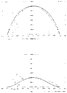
For a shift position of +100 mm and for the predetermined
profile heights, we obtain the curves plotted in Figure 6 for
the desired roll gap profile 10 and for the therein contained
component 20 of the polynomial of second degree and component 22
of the residual polynomial of fourth degree. Analogously, for a
shift position of -100 mm and for the much lower profile height,
Figure 7 shows the corresponding curves for the desired roll gap
profile 11 and its component 21 of the second-degree polynomial
and its component 23 of the residual fourth-degree polynomial.
In a modification of the prior art, i.e., a distribution,
in accordance with the invention, of the roll contourings to at
least two roll pairs P1 and P2, the rolls of a roll pair, e.g.,
P1, must be contoured in such a way that they produce the
symmetric desired roll gap profiles of second degree 20 and 21
in tree two selected shift positions. The rolls of the other
roll pair P2 must then be contoured in such a way that they
produce the desired roll gap profiles of fourth degree 22 and 23
in their two selected shift positions. If the two roll pairs Pl
and P2 are in the positions which produce the desired roll gap
27
CA 02547957 2006-06-02
profiles 20 and 22, then the resultant profile 10 is obtained in
the roll gap 6. In the opposite shift positions, the resultant
profile 11 is obtained. To determine the roll contour of a roll
pair, two desired roll gap profiles for two different shift
positions are always needed. The shift positions may be
completely different for the selected roll pairs.
Figures 8 and 9 show the roll contours 30 and 30' of the
upper roll and lower roll, respectively, which are calculated
from the desired roll gap profiles 10, 21, specifically, for the
shift position +100 mm in Figure 8 and for the shift position
-100 mm in Figure 9. Of the roll contours 30 and 30', only the
sector located in the given shift position in the reference
width can be seen in each case. For purposes of comparison, the
desired roll gap profiles 10, 11 are also plotted.
Figures 10 to 17 show how the roll gap contours with
polynomials of second and fourth degree selected in Figures 6 to
9 can be transferred to two roll pairs that can be shifted
independently of each other.
Figures 10 and 11 show the selected desired roll gap
profiles 20 and 21 of the second-degree polynomial known from
rigures 6 and 7. The determined profile heights of the shift
positions lead to the roll contours 31, 31' (Figure 12 and
Figure 13) of the upper and Lower roll for the reference width
28
CA 02547957 2006-06-02
of these roll pairs Pl, P2, P3, with which continuous variation
of the parabolically shaped roll gap between the profile heights
of the desired roll gap profiles 20 and 21 can be achieved.
In the same way, Figures 14 and I5 show the selected
desired roll gap profiles 22 and 23 of the fourth-degree
polynomial known from Figures 6 and 7. They lead to the roll
contours 32 and 32' (Figure 16 and Figure 17) of the upper roll
and lower roll and are likewise continuously variable within the
shifting range.
With a roll pair Pl, P2, P3 that has the profile of a
fourth-degree polynomial, it is thus possible to have a
sensitive effect on the so-called quarter waves from +50 pm
through 0 to
-50 um, without the adjustment of the set of rolls for the
second degree being subjected to an unfavorable change.
Figures 18 to 21 illustrate that the method is by no means
limited to the use of second- and fourth-degree polynomials and
to the influencing of quarter waves.
In Figure 18, an almost parallel desired roll gap profile
25, which is intended to open only at the edges of the rolling
stock, is required for a shift position of +100 mm. It is
formed by addition of the functional curves 24 of polynomials of
the degrees 2, 4, 6, 8, 10, 12, 14, and 16 with the profile
29
CA 02547957 2006-06-02
heights 400, 100, 60, 43, 30, 20, 14, and 10 um.
The roll gap profile is intended to vary continuously to 0
by the shift of the desired roll gap profile 25. Therefore, in
Figure 19, the roll gap profile 26 with profile height = 0 is
required for the opposite shift position of -100 mm.
Figures 20 and 21 show the corresponding roll contours 33
and 33' for the upper roll and the lower roll. We see the
opening of the roll gap that is strived for by the decrease of
the desired roll gap profile 25 (Figure 20) to the edges of the
rolling stock, which is reduced to 0 by shifting in the
direction -100 mm (Figure 21). At -100 mm, there is a parallel
roll gap with slight S-shaped curvature at the edges of the
rolling stock. A roll pair shaped in this way allows sensitive
correction of the decrease in thickness at the edges of the
rolling stock. In accordance with the invention, a roll pair of
this type can be used to advantage in combination with a roll
pair for the parabolic contour according to Figures 10 to 13.
With a suitable stand design, the additional incorporation of a
correction possibility with rolls according to Figures 14 to I7
is also conceivable.
CA 02547957 2006-06-02
The invention is not limited to the illustrated
embodiments. For example, the profile shapes of each shiftable
roll pair Pl, P2, P3 that can be produced in the roll gap 6 can
each be described by two freely selectable symmetric profiles of
an arbitrarily high degree, which are assigned to two likewise
freely selectable shift positions. In accordance with an
advantageous refinement of the invention, when a profile shape
consisting of more than one power degree is selected, the
profile heights of the individual power degrees are different
for the two freely selectable shift positions. The result of
this is that the shift position for producing the profile height
0 is different for the different power degrees, so that
complementation of the roll contours is deliberately avoided.
Alternatively, the profile height of all powers is set to 0
for one of the two selectable shift positions in order to force
complementation of the roll contours in this shift position. In
accordance with the invention, the selected shift position for
the profile 0 can also lie outside the real shifting range.
Moreover, in accordance with the invention, when a profile
shape consisting of more than two power degrees with powers
greater than 2 is selected, it is also possible for the profile
heights of the individual power degrees to be selected for the
two freely selectable shift positions in such a way that the
31
CA 02547957 2006-06-02
distance of the two profile maxima varies continuously from a
minimum to a maximum by the roll shifting.
The invention is also not limited to the use of
polynomials. For example, it is immediately possible to provide
individual roll pairs Pl, P2, P3 with contours that follow
transcendental functions or exponential functions. To this end,
the transcendental functions or exponential functions are
mathematically resolved into power series.
The operational application or the actual shifting of the
individual roll pairs is accomplished in a well-known way by
inserting the shifting systems of the roll pairs Pl, P2, P3 as
adjusting systems into a closed-loop flatness control system.
By measurement of the tensile stress distribution over the strip
width of the rolling stock, the present flatness of the rolling
stock is determined and compared with a set point. The
deviations over the strip width are analyzed by power degrees
and assigned as control values to the individual roll pairs P1,
P2, P3 according to the power degrees that can be influenced by
them. With reference to the example illustrated in Figures 6
and 7, control values for eliminating center waves would be
assigned to the roll pair for producing the desired roll gap
profiles 20, 21, and control values for eliminating quarter
;naves would be assigned to the roll pair for producing the
32
CA 02547957 2006-06-02
desired roll gap profiles 22, 23.
In the case of relatively large rolling stock thicknesses,
in which defects in the profile shape would not yet be
noticeable as flatness defects, the flatness measurement by
measurement of the tensile stress distribution is replaced in
the closed-loop control system by direct profile measurement in
the form of a measurement of the thickness distribution over the
width of the rolling stock.
33
CA 02547957 2006-06-02
List of Reference Symbols
1 four-high stand
1' six-high rolling stand
i" 10-high rolling stand
2 work rolls
3, 3', 3 " intermediate rolls
4, 4', 4 " backup rolls
rolling stock
6 roll gap, roll gap cross section,
roll gap profile in general
7 roll center
0 center of stand, center line
b-, reference width
P1, P2, P3 roll pairs, shiftable
resultant desired roll gap profile of second and
fourth degree for shift position + 100 mm
11 resultant desired roll gap profile of second and
fourth degree for shift position - 100 mm
'10 desired roll gap profile of second degree for
shift position +100 mm
21 desired roll gap profile of second degree for
shift position -100 mm
34
CA 02547957 2006-06-02
22 desired roll gap profile of fourth degree for
shift position +100 mm
23 desired roll gap profile of fourth degree for
shift position -100 mm
24 desired roll gap profile of second to sixteenth
degree for shift position +100 mm
25 additive desired roll gap profile of the profiles
from 24
26 desired roll gap profile = 0 for shift position
-100 mm
30 roll contour of the upper roll for the desired
roll gap profile according to 10 and 11
30' roll contour of the lower roll for the desired
roll gap profile according to 10 and 11
31 roll contour of the upper roll for the desired
roll gap profile according to 20 and 21
31' roll contour of the lower roll for the desired
roll gap profile according to 20 and 21
32 roll contour of the upper roll for the desired
roll gap profile according to 22 and 23
32' roll contour of the lower roll for the desired
roll gap profile according to 22 and 23
33 roll contour of the upper roll for the desired
roll gap profile according to 25 and 26
33' roll contour of the lower roll for the desired
roll gap profile according to 25 and 26