Note: Descriptions are shown in the official language in which they were submitted.
CA 02548939 2006-05-01
BACKGROUND OF THE INVENTION
Field of the Invention
[0001] The present invention relates to a vehicular wiper frame and a
rubber blade mounted thereon, and more particularly, to a frame that can allow
a
rubber blade lying against a vehicular windshield to exert vertical pressure
against the windshield. By maintaining the pressure against the windshield in
a
substantially vertical direction, the moment of a force generated between the
wiping surface of the rubber blade and the surface of the windshield is
minimized
and a secure contact between the two surfaces is maintained.
Description of the Related Art
[0002] An automotive wiper is operated by a wiper motor through a
mechanical linkage that moves the wiper arm back and forth in a predetermined
arc. Disposed on the end of the wiper arm is a detachably mounted wiper frame
to which a wiper blade made of rubber is attached.
[0003] Conventional wipers attached to wiper arms include a skeletal
frame and a blade portion mounted on the frame and contacting a windshield to
wipe it in a pendular movement.
[0004] Referring to Fig. 1, a conventional wiper 10 includes: a main frame
12 having an adapter 11 thereon for mounting the wiper arm 10; a first frame
16
symmetrically mounted on rivet joints 13 at either end of the main frame 12,
and
having a blade bracket 15 for evenly distributing load on the blade 14 and
holding
1
CA 02548939 2006-05-01
the blade 14 inserted therein; a second frame 17 symmetrically mounted on
rivet
joints 13 at either end of the first frame 16, and having blade brackets 15 on
either end thereof for evenly distributing load on the blade 14 and holding
the
blade 14 inserted therein; a blade 14 having a rail portion 19 formed thereon
along in which resilient tension springs 18 and 18a having a predetermined
elasticity are inserted, the resilient tension springs applying a
predetermined load
furnished by the first and second frames 16 and 17 along the length of the
blade
14 so that the blade 14 presses evenly against a windshield when wiping it;
and
a metallic tension spring 18 and 18a inserted along the length on either side
of
the blade 14 to support the load furnished by the first and second frames 16
and
17.
[0005] Here, in order for the main frame 12 to transmit the movement of
the wiper arm 10 to an arcuate movement of the blade 14, the wiper arm 10,
blade 14, and the tension springs 18 and 18a that provide resilience to the
blade
14 converge at one point so that they move in unison according to the movement
of the wiper arm 10. Also, the first and second frames 16 and 17 evenly
distribute load furnished by the main frame 12, and, along with the main frame
12, are press-formed to have holes formed therein to facilitate water drainage
and reduce weight.
[0006] The blade has a groove 20 (see Fig. 3) running lengthwise
therealong for guiding the blade brackets 15 of the first and second frames 16
and 17, and a separate rail portion 19 for accommodating the tension springs
18
and 18a that provide resilience to the blade 14.
2
CA 02548939 2006-05-01
[0007] In the structure of this type of wiper, because the load on the blade
is applied at certain points on the blade, it is unevenly distributed along
the length
of the blade. This unevenness causes premature wear of blade areas that are
more compressed, while less compressed areas are prone to streak or overshoot
the windshield glass underneath.
[0008] The wiper shown in Figs. 4 and 5 does not have a main frame
supporting a metal frame separately from a blade, but has tension springs
inserted in the blade 14, over which a rubber cover 21 covers the unit.
[0009] That is, the rail portion 19 is formed along the lengths on either
side of the blade 14, tension springs 18 and 18a are inserted into each rail
portion, and a rubber cover 21 that functions as a spoiler is then inserted
over the
unit to conceal the tension springs 18 and 18a.
[0010] The problem with the foresaid wiper is that the aggregate tension
of the two tension springs 18 and 18a and the rubber cover 21 necessitate the
wiper arm maintaining an increased load on the wiper for the wiper to be
operationally effective, unduly stressing the mechanism. Also, this type of
wiper
is not interchangeable with existing wiper arms on vehicles that have a
tension
present for the previously mentioned multi-point-type wiper blade.
Furthermore,
because the wiper requires the rubber spoiler-cum-cover to complete the
formation thereof, the latter item cannot be omitted.
[0011] Another conventional type of wiper, shown in Figs. 6a and 6b, is
formed with a separate spoiler 22 fitted at the top of the rubber blade that
the
tension springs are inserted into. This type of blade prevents vibration,
while
3
CA 02548939 2006-05-01
maintaining a secure and even contact with a windshield.
[0012] However, because this wiper structure has an adapter 11 and
frame 12 disposed in a vertical axis (H) direction of the adapter 11, the
frame 12
and the tension spring by themselves cannot function as a spoiler. Therefore a
separately formed spoiler is required, complicating the overall structure, and
creating the possibility of vibration or judder caused by the spoiler and wind
noise
when pressed against a windshield.
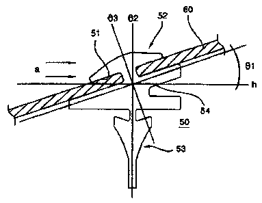
[0013] In another conventional type of wiper shown in Fig. 7, the upper
portion of the rubber blade 50 has a head portion 52 defining a mounting slot
51
for mounting the blade to a frame 60. The mounting slot 51 of the head portion
52 is inclined at an offset angle 81 according to the disposition of a frame
60,
such that a normal line of a cross section of the mounting slot 51 is offset
by a
predetermined angle from a vertical axis of the rubber blade 50. The lower
portion of the rubber blade 50 that contacts a windshield is a wiping portion
53,
which is formed perpendicularly on the vertical axis.
[0014] Thus, even without a spoiler, lifting of the wiper blade can be
prevented at high speeds.
[0015] However, although the rubber blade is structurally prevented from
lifting without a separately installed spoiler, the blade is not disposed
vertically on
the glass, so that its clearing capability diminishes.
[0016] That is, when the wiper operates and moves across the surface of
the glass about the pivoting pressure center of the motor, the blade does not
continuously contact the surface of the windshield at a perpendicular angle,
thus
4
CA 02548939 2006-05-01
failing to impart adequate contact between the blade and the windshield.
[0017] Fig. 8 is a typically shaped rubber blade 50a that is formed
symmetrically around a center of a pressing force (fs), so that despite the
position to which the wiper arm moves, the blade maintains a vertical contact
with the surface of the windshield.
[0018] The rubber blade 50 with the anti-lift characteristic shown in Fig. 7
is asymmetrical to the left and right of the pressing force (fs) from the
wiper arm
so that the wiper blade cannot maintain a vertical disposition to the
windshield
throughout the movement range of the wiper arm. That is, the angle of the
pressing force imparted on the rubber blade by the wiper arm cannot maintain a
vertical disposition with respect to the surface of the glass, so that the
wiper's
contact, wiping ability, secure disposition, etc. are insufficiently
maintained.
SUMMARY OF THE INVENTION
[0019] Accordingly, the present invention is directed to a vehicle wiper
frame that substantially obviates one or more problems due to limitations and
disadvantages of the related art.
[0020] An object of the present invention is to provide a wiper frame and
rubber blade that are asymmetrically formed to both sides of a center of
pressure
applied by the wiper arm, while maintaining the wiper blade in substantially
perpendicular contact with the surface of a windshield, without using a
separate
component.
[0021] Another object of the present invention is to provide a wiper frame
CA 02548939 2008-12-01
and a rubber blade that can maintain a predetermined lean of the entire wiper
to
prevent judder and streaking and maintain reliable contact with a windshield.
[0022] A further object of the present invention is to provide a wiper frame
and a rubber blade that maintain an even load distribution across the rubber
blade on a windshield surface to increase wiping effectiveness and firm
contact
of the blade on the windshield, while preventing noise induced by judder and
lift
while the vehicle is in motion.
[0023] Additional advantages, objects, and features of the invention will
be set forth in part in the description which follows and in part will become
apparent to those having ordinary skill in the art upon examination of the
following or may be learned from practice of the invention. The objectives and
other advantages of the invention may be realized and attained by the
structure
particularly pointed out in the written description and claims hereof as well
as the
appended drawings.
[0024] To achieve these objects and other advantages and in accordance
with the purpose of the invention, as embodied and broadly described herein,
there is provided a vehicular wiper frame that supports and presses a rubber
blade on a vehicle's windshield surface, and is coupled through an adaptor to
a
wiper arm that presses and moves the rubber blade against and across the
windshield surface. The wiper frame with a predetermined resilience has a slot
that guides a sliding insert formed on the rubber blade to mount the rubber
blade
so that load thereon presses evenly across the windshield surface. The
mounting portion at the upper end of the rubber blade is disposed slantingly
at a
6
CA 02548939 2006-05-01
predetermined angle against and mounted to the frame. The mounting portion
supports a wiping portion having a contact surface forming the bottom end of
the
rubber blade. To allow the wiping portion of the rubber blade to apply
vertical
force on and contact the windshield surface by being mounted on the frame
through the mounting portion, the slot, for mounting the rubber blade to
create a
predetermined offset between the centers of the mounting portion and the
wiping
portion of the rubber blade, is formed in a position so that the pressure of
the
wiper arm can fall at the center point of the wiping portion.
[0025] In another aspect of the present invention, there is provided a
vehicular rubber blade that is mounted to a frame with a certain elasticity
that
evenly distributes load along the rubber blade onto the windshield surface.
The
frame is coupled through an adapter to a wiper arm and presses the rubber
blade
against the windshield surface to simultaneously move the rubber blade across
the windshield surface. The rubber blade has a sliding insert into which the
frame is installed. The top of the rubber blade is slanted and installed at a
predetermined angle at a mounting portion with respect to the frame, and the
lower end of the rubber blade has a wiping portion that extends from the
mounting portion and includes a contact surface contacting the windshield
surface. The mounting portion and wiping portion are formed so that their
centers are offset from one another by a predetermined distance, so that the
pressing force of the wiper arm passes through the central point of the wiping
portion.
[0026] It is to be understood that both the foregoing general description
7
CA 02548939 2006-05-01
and the following detailed description of the present invention are exemplary
and
explanatory and are intended to provide further explanation of the invention
as
claimed.
BRIEF DESCRIPTION OF THE DRAWINGS
[0027] The accompanying drawings, which are included to provide a
further understanding of the invention and are incorporated in and constitute
a
part of this application, illustrate embodiment(s) of the invention and
together with
the description serve to explain the principle of the invention. In the
drawings:
[0028] Fig. 1 is an exploded perspective view of a vehicular wiper
structure according to the related art;
[0029] Fig. 2 is an exploded perspective view of the assembling structure
of spring rails on a wiper blade according to the related art;
[0030] Fig. 3 is a sectional view of a blade assembled with spring rails
according to the related art;
[0031] Fig. 4 is a perspective view of another type of wiper according to
the related art;
[0032] Fig. 5 is a sectional view of the wiper shown in Fig. 4;
[0033] Fig. 6 shows a further type of the wiper according to the related art,
where Fig. 6A is a perspective view and Fig. 6B is a side view thereof;
[0034] Fig. 7A is a sectional view of the structure of a rubber blade
according to the present invention, and Fig. 7B shows the asymmetrical
operation of the rubber blade in terms of pressure direction;
8
CA 02548939 2006-05-01
[0035] Fig. 8A is a sectional view showing the structure of a wiper blade
according to the related art, and Fig. 8B shows the symmetrical operation of
the
rubber blade in terms of pressure direction;
[0036] Fig. 9 is a perspective view showing an overall structure of a
rubber blade mounted on a wiper frame according to the first embodiment of the
present invention;
[0037] Fig. 10 is a plan view of the wiper according to the first
embodiment of the present invention;
[0038] Fig. 11 is a graph showing the load distribution on the wiper frame
in Fig. 10 and the response of the frame to the load;
[0039] Fig. 12 is a sectional view showing an example of an installed
rubber blade according to the first embodiment of the present invention;
[0040] Fig. 13 is a plan view of a rubber blade installed on a wiper
according to the second embodiment of the present invention;
[0041] Fig. 14 is a side view of the wiper according to the second
embodiment of the present invention; and
[0042] Fig. 15 is a sectional view showing the structure and shape of the
rubber blade according to the second embodiment of the present invention.
DETAILED DESCRIPTION OF THE INVENTION
[0043] Reference will now be made in detail to the preferred embodiments
of the present invention, examples of which are illustrated in the drawings.
Wherever possible, the same reference numbers will be used throughout the
9
CA 02548939 2006-05-01
drawings to refer to the same or like parts.
[0044] Fig. 9 is a perspective view showing an overall structure of a
rubber blade mounted on a wiper frame according to the first embodiment of the
present invention. Fig. 10 is a plan view of the wiper according to the first
embodiment of the present invention. Fig. 11 is a graph showing the load
distribution on the wiper frame in Fig. 10 and the response of the frame to
the
load. Fig. 12 is a sectional view showing an example of an installed rubber
blade
according to the first embodiment of the present invention. Fig. 13 is a plan
view
of a rubber blade installed on a wiper according to the second embodiment of
the
present invention. Fig. 14 is a side view of the wiper according to the second
embodiment of the present invention. Fig. 15 is a sectional view showing the
structure and shape of the rubber blade according to the second embodiment of
the present invention.
[0045] Hereinafter, the wiper frame according to the present invention will
be described in the first embodiment, and the rubber blade of the wiper
according
to the present invention will be described in the second embodiment.
[0046] <FIRST EMBODIMENT>
[0047] Referring to Figs. 9 through 12, a wiper frame 200 according to the
first embodiment of the present invention supports and presses a rubber blade
100 on a vehicle's windshield surface 70, and is coupled through an adaptor 90
to a wiper arm 80 such that it presses and moves the rubber blade 100 against
and across the windshield surface 70. The wiper frame 200 with a
predetermined resilience has a slot 201 that guides a sliding insert 101
formed
CA 02548939 2008-12-01
on the rubber blade 100 to mount the rubber blade 100 so that load thereon
presses evenly across the windshield surface 70. The mounting portion 102 at
the upper end of the rubber blade 100 is disposed at a predetermined angle and
mounted to the frame 200. The mounting portion 102 supports a wiping portion
104 having a contact surface 103 defining the bottom end of the rubber blade
100.
[0048] To allow the wiping portion 104 of the rubber blade 100 to apply a
vertical force on and contact the windshield surface 70 by being mounted on
the
frame 200 through the mounting portion 102, the slot 201 that mounts the
rubber
blade 100 to create a predetermined offset L1 between the center points of the
mounting portion 102 and the wiping portion 104 of the rubber blade 100 is
formed in a position so that the pressure fsl-fs2 of the wiper arm 80 can fall
at
the central point of the wiping portion 104.
[0049] The shape of the slot 201 formed in the frame 200 is symmetric
about the center (fp) of the frame 200, as shown in Fig. 11.
[0050] Also, the shape of the slot 201 formed in the frame 200 has a
curvature Cv that curves gently toward both ends.
[0051] A wiper frame 200 according to the present invention may be
applied to a wiper integrally formed with an elastic spring rail, from which
an
adaptor 90 is bent to connect to a wiper arm. That is, a frame 60 may be
designed to support a rubber blade 100 against a windshield surface 70 while
being coupled through an adapter 90 to a wiper arm 80 that moves the wiper
across the windshield surface 70. Specifically, the wiper frame 60 is
installed
11
CA 02548939 2008-12-01
along the sliding insert 101 of the rubber blade 100, and is a spring rail
having a
predetermined elasticity for distributing the load on the rubber blade 100
evenly
across the windshield surface 70. This may be applied to wiper structures with
frames and blades that have built-on spoilers for reducing air resistance by
being
formed at a certain angle, in order to prevent lift of the wiper.
[0052] <SECOND EMBODIMENT>
[0053] Referring to Figs. 13 through 15, a rubber blade 100 of a wiper
according to the second embodiment is mounted to a frame 200a with a certain
elasticity that evenly distributes load along the rubber blade 100 onto the
windshield surface 70. The frame 200a is coupled through an adapter 90 to a
wiper arm 80 and presses the rubber blade 100 against the windshield surface
70 to simultaneously move the rubber blade across the windshield surface 70.
The rubber blade has a sliding insert 101 into which the frame 200a is
installed.
[0054] The top of the rubber blade 100 is slanted and installed at a
predetermined angle at a mounting portion 102 with respect to the frame 200a,
and the lower end of the rubber blade 100 has a wiping portion 104 that
extends
from the mounting portion 102 and includes a contact surface 103 contacting
the
windshield surface 70.
[0055] The mounting portion 102 and wiping portion 104 are formed so
that their center points are offset from one another by a predetermined
distance
L1, so that the pressing force (fs) of the wiper arm 80 passes through the
central
point P4 of the wiping portion 104.
[0056] The offset distance L1 between the mounting portion 102 and the
12
CA 02548939 2008-12-01
wiping portion 104 of the rubber blade 100 may be deemed the distance between
the center point P1 of the mounting portion 102 and the center P2 of the
wiping
portion 104.
[0057] The pressing force (fs) of the wiper arm 80 applied to the rubber
blade 100 passes between the center point P2 of the wiping portion 104 and the
contact point P3 on the windshield surface 70 through the offset between the
mounting portion 102 and the wiping portion 104.
(0058] The rubber blade 100 according to the present invention may be
applied to a wiper that is a tensile member having an integrally formed frame
and
spring with an adapter bent therefrom. That is, the frame 200a is coupled
through its adapter 90 to the wiper arm 80 that presses the rubber blade 100
against a windshield surface 70 and simultaneously moves the rubber blade
across the windshield surface 70, where the rubber blade has a sliding insert
101
into which the spring rail (with a certain elasticity that evenly distributes
load
along the rubber blade 100 onto the windshield surface 70) is installed. This
may
be applied to wiper structures with frames and blades that have built-on
spoilers
for reducing air resistance by being formed at a certain angle, in order to
prevent
lift of the wiper.
[0059] The wiper frame and rubber blade according to the embodiments
of the present invention have the following characteristics.
[0060] In order to prevent lift of the wiper, the wiper structure shown in
Fig. 7A positions the frame 60 and the rubber blade 50 at an overall slant of
81,
so that they are disposed at an angle 03 with respect to a vertical axis 82.
Here,
13
CA 02548939 2006-05-01
the driving force of the motor remains constant, and when the pressing force
(fs)
of the wiper arm is transferred to the rubber blade 50, the point of the
pressing
force (fs) is applied asymmetrically in directions (a) and (b) (see Fig. 7B),
so that
the contacting end of the rubber blade is not maintained in a vertical
disposition
with respect to the windshield surface. That is, the blade does not evenly
contact
the windshield surface due to the asymmetrical pressing force in directions
(a)
and (b).
[0061] Comparatively, Fig. 8A shows a rubber blade 50a according to the
related art. This blade is not configured at an angle, so that the pressing
force
(fs) is symmetrically and evenly applied vertically on the windshield surface
70 in
directions (a) and (b), and regardless of the rotation and position of the
wiper, as
shown in Fig. 8B.
[0062] The present invention changes the configuration of the frame
and/or the rubber blade so that an ideal contact is maintained under all
circumstances, which is shown in the first and second embodiments.
[0063] Figs. 9 and 10 show a frame structure of a wiper according to the
first embodiment of the present invention, which includes a spoiler function
to
prevent lift of the wiper, as illustrated in Fig. 7. Fig. 11 shows the even
distribution of the initial applied pressure (fsl) and the latter applied
pressure
(fs2) from the wiper arm along sectors A through E along the wiper frame in
Fig.
10, and Fig. 12 shows the slot configuration of a wiper frame according to the
first embodiment of the present invention.
[0064] Figs. 13 and 14 show the structure of a rubber blade according to
14
CA 02548939 2008-12-01
the second embodiment of the present invention, with an air spoiler function
for
preventing lift of the wiper as that shown in Fig. 7. Fig. 15 shows the
structure
and shape of the rubber blade according to the second embodiment of the
present invention.
[0065] <FIRST EMBODIMENT>
[0066] Referring to Figs. 9 through 12, a rubber blade 100 installed to a
frame 200 according to the present invention has a mounting portion 102 at its
top that is disposed at a predetermined angle and installed to the frame 200.
The bottom portion of the rubber blade 100 has a wiping portion 104 that
extends
from the mounting portion 102 and has a contact surface 103 that contacts the
windshield surface 70.
[0067] Here, the center points of the mounting portion 102 and wiping
portion ' 104 are offset by a distance L1 from each other, due to the position
of the
slot 201 of the frame 200. When the pressing force (fs) or (fsl-fs2) is
applied by
the wiper arm 80, it passes through the central point P4 of the wiping portion
104.
Thus, the slant of the slot 201 of the frame 200 and its shape take into
consideration and are formed at the point of applied pressure of the wiper
arm.
[0068] According to the shape and position of the slot 201 of the frame
200, an offset is formed between the mounting portion 102 and washing portion
104 of the rubber blade 100, with the offset L1 being the distance between the
central point P1 of the mounting portion 102 and the central point P2 of the
washing portion 104.
[0069] The pressing force (fs, or fsl -fs2) of the wiper arm 80 that is
CA 02548939 2006-05-01
applied to the rubber blade 100 passes between the center point P2 of the
wiping
portion 104 and the contact point P3 that contacts the windshield surface 70,
by
means of the structural offset between the mounting portion 102 and the wiping
portion 104.
[0070] The shape of the slot 201 formed in the frame 200 is formed
symmetrically to either side of the center (fp) of the frame 200, as shown in
Fig.
11, and the shape of the slot 201 formed in the frame 200 has a gradual curve
(Cv) towards either end thereof.
[0071] That is, when pressure is equally distributed along sectors A
through E from the center (fp) of the pressing force, the contact surface 103
of
the wiping portion 104 of the rubber blade is resultantly offset from a
vertical
disposition on the windshield surface. However, when the shape of the slot 201
of the frame 200 is curved similarly, the angle of the contact surface of the
wiping
portion 104 receives elasticity and is disposed at an angle almost
perpendicular
to the glass.
[0072] Accordingly, when the mounting structure of the rubber blade in the
frame is configured according to the present invention, in the case of an
asymmetrical pivoting movement of the rubber blade contacting the windshield
surface, a spoiler effect for preventing lift of the wiper at high speed can
be
achieved without using a separate spoiler. Therefore, the problem of not being
able to maintain the angle of the rubber blade (which has vertical pressure
applied thereon) at an angle vertical to the windshield surface can be easily
overcome by using the offset maintained between the point of pressure exerted
16
CA 02548939 2008-12-01
by the wiper arm and the center point of actual contact on the windshield
surface
as a center.
[0073] <SECOND EMBODIMENT>
[0074] Referring to Figs. 13 through 15, the upper portion of the rubber
blade 100 has the mounting portion 102 that is disposed and installed at a
predetermined angle with respect to the frame 200a, and the lower end of the
rubber blade 100 includes a wiping portion 104 extending from the mounting
portion 102 and having a contact surface 103 that contacts the windshield
surface 70.
[0075] The mounting portion 102 and the wiping portion 104 are formed
such that their respective center points are offset by a predetermined
distance
L1. When a pressing force (fs) is applied by the wiper arm 80, it passes
through
the central point P4 of the wiping portion 104. Accordingly, the angle and
shape
of the rubber blade is formed to be at the center of pressure applied by the
wiper
arm.
[0076] The offset distance L1 between the mounting portion 102 and
wiping portion 104 of the rubber blade 100 is set as the distance between the
center point P1 of the mounting portion 102 and the center point P2 of the
wiping
portion 104.
[0077] The pressing force (fs) of the wiper arm 80 on the rubber blade 100
is structurally configured to pass through the offset between the mounting
portion
102 and the wiping portion 104 and through between the center point P2 of the
wiping portion 104 and the contact point P3 contacting the windshield surface
70.
17
CA 02548939 2006-05-01
[0078] Accordingly, when the mounting structure of the rubber blade in the
frame is configured according to the present invention, in the case of a wiper
structure with an asymmetrical pivoting movement of the rubber blade
contacting
the windshield surface, a spoiler effect for preventing lift of the wiper at
high
speed can be achieved without using a separate spoiler. Therefore, the problem
of not being able to maintain the angle of the pressure applied on the rubber
blade at an angle vertical to the windshield surface can be easily overcome by
using the offset maintained between the point of pressure exerted by the wiper
arm and the center point of actual contact on the windshield surface as a
center.
[0079] The wiper frame and rubber blade according to the present
invention act as a spoiler for oncoming air, and maintain the contacting angle
between the rubber blade and the windshield surface close to a perpendicular
90 , regardless of the pressure point exerted by the wiper arm and the motion
provided by the motor, so that a close contact is maintained between the
rubber
blade and windshield surface for superb wiping ability.
[0080]
It will be apparent to those skilled in the art that various modifications and
variations can be made in the present invention. Thus, it is intended that the
present invention covers the modifications and variations of this invention
provided they come within the scope of the appended claims and their
equivalents.
18