Note: Descriptions are shown in the official language in which they were submitted.
CA 02549779 2006-06-15
WO 2005/062757 PCT/US2004/041050
1
DESCRIPTION
ELECTROMAGNETIC RADIATION ASSEMBLY
TECHNICAL FIELD
The present invention relates to an electromagnetic radiation assembly, and
more
specifically, to an assembly having particular utility when coupled with the
controls of an
overland vehicle, or the like, and which, on the one hand, may operate as a
combined
warning lamp, and rearview mirror assembly, and further is operable to
illuminate the
side, and region adjacent to the overland vehicle to assist an operator or
passenger
when they are entering, or departing from the vehicle during reduced periods
of visibility.
BACKGROUND ART
The beneficial effects of employing auxiliary signaling assemblies have been
disclosed in various U.S. Patents including U.S. Patent No. 6,005,724 and
6,076,948,
the teachings of which are incorporated herein. Yet further, numerous designs
of
signaling assemblies, having various semitransparent mirrors including
dichroic, and
electrochromic type mirrors are disclosed in Patents 5,014,167; 5,207,492;
5,355,284;
5,361,190; 5,481,409 and 5,528,422. These references are also incorporated by
reference herein. Assemblies such as what is shown in U.S. Patent No.
6,005,724 and
6,076,948 have been incorporated into other mirror assemblies such as
electrochromic
mirror assemblies as more fully shown in U.S. Patents No. 6,512,624, and
6,356,376,
the teachings of which are also incorporated by reference herein. In addition
to providing
an auxiliary signaling device, such prior art assemblies have also included
auxiliary
lighting which has typically been remotely actuated in order to provide an
exterior vehicle
security light to aid and assist operators and passengers during night time
hours.
Examples of such assemblies are shown in U.S. Patent Nos. 5,371,659 and
5,497,305 to
name but a few.
While these prior art assemblies, as discussed above, have operated with a
great
deal of success, and have enjoyed wide commercial acceptance, there are
shortcomings
with respect to the individual designs which have detracted from their
usefulness. For
example, with respect to U.S. Patent No. 5,371,659 and 5,497,305 these
particular
assemblies, while effective for their intended purposes, are complex in their
overall
designs. This, of course, increases the cost of the resulting exterior mirror
which
incorporates same. As will be readily recognized from the study of the
drawings of these
respective prior art patents, the exterior mirror housing that must be
utilized for this type
of arrangement must be larger than what it would normally be merely because it
needs
CA 02549779 2006-06-15
WO 2005/062757 PCT/US2004/041050
2
to accommodate the assembly which projects visible light into the region
adjacent to the
overland vehicle. Still further, separate electrical connections must be made
to the
portion of the assembly which projects light into this region, thereby adding
complexity to
the wire harness that must be provided to service such a mirror, especially if
this mirror
incorporates an electrochromic type mirror which must also be provided with a
source of
electrical power in order to operate. These somewhat larger exterior mirror
housings, of
course, detract from the aesthetic appearance of the overland vehicle which is
equipped
with same and may not be useful on smaller or more compact vehicle platforms.
In the present invention, the inventors have departed from the teachings of
the
prior art by providing a novel arrangement which, in a first mode of
operation, permits the
electromagnetic radiation assembly to operate as an exterior warning lamp that
can alert
operators of vehicles traveling in adjacent lanes; and which further, in a
second mode of
operation, will emit visible light which is operable to illuminate the
adjacent area and
region along the side of the vehicle to assist an operator or passenger who is
either
entering or exiting the vehicle or working along same during periods of
reduced visibility.
These and other aspects of the present invention will be discussed in greater
detail hereinafter.
SUMMARY
Therefore, one aspect of the present invention relates to an electromagnetic
radiation assembly which includes a supporting substrate having opposite
surfaces, and
having a region through which an electromagnetic radiation signal may pass;
first and
second electromagnetic radiation emitters positioned adjacent to one of the
surfaces
defined by the substrate, and which, when energized, emit electromagnetic
radiation;
and a single reflector disposed in eccentric reflecting relation relative to
the first and
second electromagnetic radiation emitters, and wherein the emitted
electromagnetic
radiation produced by the first and second electromagnetic radiation emitters
is reflected
by the single reflector and passes through the supporting substrate region
which passes
electromagnetic radiation in different directions.
Another aspect of the present invention relates to an electromagnetic
radiation
assembly which includes a supporting substrate having opposite first and
second
surfaces, and having a first region which allows electromagnetic radiation to
pass
therethrough, and a second region adjacent to the first region; a reflector
positioned
adjacent to the second surface of the supporting substrate and oriented in a
position
which is adjacent to the first region; and at least two electromagnetic
radiation emitters
mounted on, or adjacent to the second surface of the supporting substrate, and
which,
CA 02549779 2006-06-15
WO 2005/062757 PCT/US2004/041050
3
when individually energized, emit electromagnetic radiation which is reflected
by the
reflector through the first region of the supporting substrate, and wherein
the energizing
of one of the electromagnetic radiation emitters produces visibly discernible
electromagnetic radiation which is reflected, at least in part, by the
reflector, and which
passes through the first region and predominately in a first direction, and
wherein
energizing of the other of the two electromagnetic radiation emitters emits
visibly
discernible electromagnetic radiation which is reflected, at least in part, by
the reflector,
and which passes through the first region and predominately in a second
direction which
is angularly displaced relative to the first direction.
Still another aspect of the present invention relates to an electromagnetic
radiation assembly which includes, a supporting substrate having opposite
surfaces, and
having a region through which an electromagnetic radiation signal may pass; a
plurality
of first and second electromagnetic radiation emitters positioned adjacent to
one of the
surfaces defined by the supporting substrate, and which, when energized, emit
visibly
discernable electromagnetic radiation; and a multi-faceted reflector disposed
in covering,
eccentric reflecting relation relative to the plurality of first and second
electromagnetic
radiation emitters, and wherein the emitted electromagnetic radiation produced
by the
first electromagnetic radiation emitters is substantially reflected through
the substrate
region in a first direction by a first group of reflector facets, and the
emitted
electromagnetic radiation produced by the second electromagnetic radiation
emitters is
substantially reflected by a second group of reflector facets through the
substrate region
in a second direction.
These and other aspects of the present invention will be discussed in greater
detail hereinafter.
BRIEF DESCRIPTION OF THE DRAWINGS
Preferred embodiments of the invention are described below with reference to
the
following accompanying drawings.
Fig. 1 is a greatly simplified, perspective, exploded view of the
electromagnetic
radiation assembly of the present invention.
Fig. 2 is a fragmentary, greatly enlarged, perspective view of the
electromagnetic
radiation assembly of the present invention.
Fig. 3 is fragmentary, transverse, vertical sectional view taken through one
of the
reflector cavities of the electromagnetic radiation assembly of the present
invention and
which is shown in an assembled arrangement.
CA 02549779 2006-06-15
WO 2005/062757 PCT/US2004/041050
4
Fig. 4 is a top, plan view of an overland vehicle of conventional design, and
which
illustrates the approximate projected pattern of light as provided by the
electromagnetic
radiation assembly of the present invention while operating in a first mode.
Fig. 5 is a perspective, side elevation view of an overland vehicle of
conventional
design, and which illustrates the approximate projected pattern of light as
provided by
the electromagnetic radiation assembly of the present invention while
operating in a first,
and in a second mode.
Fig. 6 is a simplified, perspective, side elevation view of the
electromagnetic
radiation assembly of the present invention, and which shows the approximate
projected
pattern of light provided by the invention when operating in a first mode.
Fig. 7 is a simplified, perspective, side elevation view of .the
electromagnetic
radiation assembly of the present invention, and which shows the approximate
projected
pattern of light provided by the invention when operating in a second mode.
Fig. 8 is a greatly exaggerated, partial, vertical sectional view of the
electromagnetic radiation assembly, and which is taken from a position along
line 8-8 in
Fig. 1.
Fig. 9 is a greatly enlarged, partial, vertical, sectional view of the
electromagnetic
radiation assembly and which is taken from a position along line 8-8 of Fig.
1, and which
illustrates an alternative form of the invention from that shown in Fig. 8.
Fig. 10 is a greatly enlarged, partial, vertical, sectional view of the
electromagnetic radiation assembly, and which illustrates yet another form of
the
invention.
Fig. 11 is a partial, transverse, vertical, sectional view of yet another form
of the
invention.
DETAILED DESCRIPTION OF THE PREFERRED EMBODIMENTS
Referring more particularly to the drawings, the electromagnetic radiation
assembly of the present invention is generally indicated by the numeral 10, in
Fig. 1, and
following. For illustrative convenience the electromagnetic radiation assembly
10 of the
present invention, and which is shown and described herein, is discussed as it
would be
configured if it was installed on an overland vehicle 11 of conventional
design. As
discussed in many of the earlier prior art references, which are incorporated
by reference
herein, the electromagnetic radiation assembly (hereinafter referred to as
assembly 10)
of the present invention is adapted to operate as a combination rearview
mirror and
visual signaling device, and wherein the visual signaling device provides a
visual signal
which is capable of being seen from locations which are laterally and
rearwardly of the
CA 02549779 2006-06-15
WO 2005/062757 PCT/US2004/041050
overland vehicle 11, when the invention is operating in a first mode. During
this first
mode of operation the visual signal, at a significantly reduced intensity, can
normally be
seen by the operator of the same vehicle. Still further, the invention, when
operating in a
second mode, is operable to illuminate the side, and region adjacent to the
overland
5 vehicle, in order to assist an operator or passenger when they are entering
or exiting the
vehicle during reduced periods of visibility. These first and second modes of
operation
will be discussed in greater detail hereinafter.
As best seen in Figs. 4 and 5, the assembly 10 of the present invention is
mounted on an overland vehicle 11 of conventional design. The overland vehicle
11 has
a front or forward portion 12, and a rearward portion 13. The overland vehicle
11 further
has a passenger compartment 14 which includes a front seat 15. Still further,
the
overland vehicle 11 has a longitudinal axis which is generally indicated by
the numeral
16, and an operator's position 20. The overland vehicle also includes
locations 21 for a
pair of exterior rearview mirrors. The overland vehicle 11 also has a hand
operated
directional signaling switch; and brake (not shown), and which when utilized,
provides an
electrical signal which may alert drivers of other vehicles in the immediate
vicinity that
the overland vehicle 11 is about to change directions, turn, change lanes,
etc. Yet
further, other signals may also be provided from the overland vehicle from
other devices
such as a hazard warning switch. In addition to the foregoing, the overland
vehicle 11
may be equipped with a radio frequency receiver 22 and which receives an RF
signal
which is transmitted from a key fob held by the operator of the overland
vehicle (not
shown). This radio signal, once received, is operable to unlock the various
doors of the
overland vehicle, and further, is useful in actuating the second mode of
operation of the
electromagnetic radiation assembly 10, as will be discussed below.
As best illustrated in Fig. 4, an operator 30, when positioned in the
operator's
position 20, has a field of view which extends approximately 180 degrees from
the
operator's position towards the forward portion 12 of the vehicle. Further,
and by using a
pair of the assemblies 10, which are individually located at the positions 21
on the
exterior portion of the overland vehicle 11, the operator may, by looking
along
predetermined lines of sight, view areas beyond his normal field of view, and
rearwardly
of the operator's position 20. In particular, the operator 30 has a first line
of sight 31,
which extends from the operator 30 to the assembly 10, which is located on the
driver's
side of the overland vehicle 11, and which permits the operator to view
rearwardly of the
vehicle along the driver's side thereof. The operator 30 additionally has a
second line of
sight, 32 which extends from the operator 30 to the passenger side of the
overland
vehicle and therefore permits the operator to view rearwardly along that side
of the
CA 02549779 2006-06-15
WO 2005/062757 PCT/US2004/041050
6
overland vehicle. Furthermore, the operator has a third line of sight which
extends from
the operator's position to the interior rearview mirror (not shown). As
depicted in the
drawings, the assembly 10 of the present invention, in a first mode of
operation, provides
illumination zones 33 which extend rearwardly of the overland vehicle 11 and
predominately out of the line of sight of the operator 30. These illumination
zones have a
predetermined beam spread 34 of approximately six meters when measured at a
distance of about 8 meters from the assembly 10. Further, the deviation angle
of the
driver's side and passenger's side illumination zone may be varied based upon
the
geometry of the overland vehicle 11 upon which the assembly 10 is utilized. In
a first
mode of operation 35, and when energized, the assembly 10 is operable to
produce
visibly discernible electromagnetic radiation which is provided to the
illumination zones
33 in order to signal adjacent vehicles or other interested parties regarding
the actions of
the operator of the overland vehicle 11. Further in a second mode of operation
36 (Fig.
5), the assembly 10, when energized, is operable to produce visibly
discernable light
which illuminates the side, and region adjacent the overland vehicle to aide,
and assist
an operator or passenger who may be entering, exiting, or working along the
side of the
overland vehicle 11.
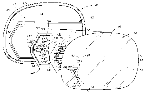
Referring now to Fig. 1, the assembly 10 of the present invention is
incorporated
into a mirror housing which is generally indicated by the numeral 40, and
which is
operable to be mounted at mirror locations 21 on the exterior surface of the
overland
vehicle 11. The mirror housing or enclosure has a rear wall 41 (Fig. 6), and a
sidewall
42 which extends outwardly therefrom. The sidewall 42 has a peripheral edge 43
which
defines an aperture 44 having given dimensions. The rear wall 41, and sidewall
42
further defines a cavity 45 which is operable to receive and enclose the
assembly 10 and
other associated devices such as a bezel 46. It should be understood that the
bezel may
provide a cavity 47 which receives the assembly 10, and which further will
movably
support the assembly 10 within the housing 40. The assembly 10 can then be
positionally adjusted, either manually, or remotely, as by a motorized
actuator (not
shown) to a given angular orientation relative to the first and second lines
of sight 31 and
32 of the operator 30 of the overland vehicle 11. This provides a means by
which the
operator 30 may adjust his given field of view rearwardly of the overland
vehicle 11.
The assembly 10 of the present invention as shown in Fig. 1, and following,
includes a semitransparent mirror which is generally indicated by the numeral
50, and
which has a front or exterior facing surface 51, and an opposite, or rearward
facing
surface 52. The semitransparent mirror further is defined by a peripheral edge
53, which
substantially corresponds in shape and size to the aperture 44 which is
defined by the
CA 02549779 2006-06-15
WO 2005/062757 PCT/US2004/041050
7
peripheral edge 43 of the housing 40. When assembled, the semitransparent
mirror 50
substantially occludes the aperture 44. The semitransparent mirror 50 of the
subject
invention 10 may take on several forms. Referring now to Figs. 8 and 9, the
semitransparent mirror 50 comprises, in a first form, a supporting,
substantially
transparent or translucent substrate 54, which has a forward facing surface
55, and an
opposite rearward facing surface 56. A highly reflective mirror coating 60 is
formed on
the rearward facing surface 56. As should be understood, the mirror coating
may be
applied, in an alternative form, to the forward facing surface of the
substrate 54. The
discussion which follows, therefore, is applicable to mirrors where the mirror
coating is
applied to either the forward or rearward facing surfaces thereof. The highly
reflective
mirror coating 60 may comprise any number of different highly reflective, or
mirror like
coatings, or substances, such as chromium and the like, and which may be
applied or
formed in a manner which provides a commercially acceptable reflective
surface. For
automotive applications, the resulting reflectance of the semitransparent
mirror 50 should
generally be, on average, greater than about 35%.
As best seen by reference to Fig. 1, the semitransparent mirror 50 has a first
or
primary region 61 and through which a visibly discernable electromagnetic
radiation
signal may pass; and an adjacent secondary region 62. While only two regions
are
shown and discussed herein, it is, of course, possible to have a plurality of
secondary
regions depending upon the end use of the assembly 10. As a general matter
however,
the first or primary region 61 passes a portion of the visibly discernible
electromagnetic
radiation directed at same, while simultaneously reflecting a given percentage
of the
visibly discernible electromagnetic radiation which comes from the ambient
environment.
On the other hand, the secondary region is operable to reflect visibly
discernible
electromagnetic radiation, and is otherwise considered nominally opaque. As
discussed
above, the combined average reflectance of the overall surface area of the
semitransparent mirror 50, including both the primary and secondary regions,
is normally
greater than about 35% when employed for automotive applications. In other
industrial
applications, the average reflectance may be lower or higher depending upon
the
desired end use. As seen in the drawings, the secondary region 62 is
substantially
continuous and reflects, for automotive applications, greater than about 35%
of visible
electromagnetic radiation and passes less than about 10% of visibly
discernable
electromagnetic radiation. The first or primary region 61, on the other hand,
passes less
than about 50% of visible electromagnetic radiation, and further reflects on
average less
than about 40% of visible electromagnetic radiation. The ranges noted above
have been
CA 02549779 2006-06-15
WO 2005/062757 PCT/US2004/041050
8
found suitable for automotive applications, however, it will be recognized
that other
broadened, or narrowed ranges may be useful for other industrial applications.
As best seen in Fig. 9, in a first form of the invention 10, the mirror
coating 60 in
the first or primary region 61, of the semitransparent mirror 50 includes a
plurality of
discreet apertures 63, and which may be formed in a number of given patterns,
and in
various densities. As recognized by a study of Fig. 9, which is greatly
exaggerated, the
plurality of discreet apertures .extend, in this form of the invention 10,
through the mirror
coating 60 to the rearward surface 56 of the transparent substrate 54. In an
alternative
form of the invention, as shown in Fig. 8, reduced thickness areas 64 may be
formed in
the mirror coating 60. These reduced thickness areas allow increased amounts
of visibly
discernable electromagnetic radiation to pass therethrough in relative
comparison to the
adjacent thicker areas in the secondary region 62. Therefore, the secondary
region 62
has a first thickness dimension for the mirror coating 60 which is greater
than the
thickness dimension of the mirror coating 60 which defines the first or
primary region 61.
Still further, these two approaches may be combined, and wherein the apertures
63 be
joined with a reduced thickness area 64.
Referring now to Fig. 10, another form of a semitransparent mirror 50 is
shown,
and which is useful in the present invention 10. In this form of the
invention, the
substrate 54 has applied thereto a dichroic mirror coating 65. The usefulness
of dichroic
mirrors, of various types, have been discussed in various U.S. Patents
including U.S.
Patent No. 5,014,167 and 5,207,492 to name but a few. The dichroic mirror
coatings 65
which are useful for such mirrors are also well known in the art, and further
discussion
regarding these dichroic mirror coatings is not warranted. As seen in Fig. 10,
a
substantially opaque masking layer 66 is applied over the secondary region 62
thereby
making the secondary region substantially opaque, and further permitting
visible
electromagnetic radiation to be passed through the first or primary region 61
which is
unmasked. As discussed in the earlier prior art patents, the dichroic mirror
coating 65
may be selected to pass given bands of visibly discernable electromagnetic
radiation in
greater amounts than other bands of electromagnetic radiation thereby making -
the
resulting semitransparent mirror 50, on average, an acceptable reflector of
visibly
discernable electromagnetic radiation, while simultaneously allowing increased
amounts
electromagnetic radiation of the selected band of electromagnetic radiation to
pass
therethrough.
Yet a further form of an acceptable semitransparent mirror 50 which may be
employed in the present invention 10 is seen in Fig. 11, and which illustrates
a prior art
arrangement for a signaling assembly which incorporates an electrochromic
mirror which
CA 02549779 2006-06-15
WO 2005/062757 9 PCT/US2004/041050
is generally indicated by the numeral 70. The electrochromic mirror 70
includes a front
or transparent element or substrate 71, and further has applied to its
rearwardiy facing
surface, a transparent electrically conductive material 72, and a layer of
color
suppression material which is generally indicated by the numeral 73. In the
arrangement
as shown irk, Fig. 11, an electrochromic fluid or gel 74 is provided, and
which is
sandwiched between the front element 71 and a rear element 75 which is also
transparent. As seen in Fig. 11, a conductive thin film reflector/electrode 76
is positioned
in spaced relation relative to the front element 71. Still further, a
plurality of apertures 77
are formed in this conductive thin film reflector/electrode 77 and which will
permit the
passage of visibly discernible electromagnetic radiation to pass therethrough
forming the
illumination zone 33. As seen in Fig. 11, a light source 80 is provided, and
which is
disposed at an oblique orientation relative to the electrochromic mirror 70.
Still further, a
light baffle assembly 81 is provided and which is substantially identical to
that described
in our previous U.S. Patent No. 6,257,746. The teachings of which are
incorporated by
reference herein. The light baffle assembly is operable to allow the passage
of visibly
discernable electromagnetic radiation to strike the electrochromic mirror 70
in a given
orientation such that it can be transmitted into the illumination zone 33. A
light sensor 82
is provided and which is oriented in a fashion so as to receive ambient
electromagnetic
radiation passing through apertures 83 which are formed in the thin film
reflector/electrode 76 thereby allowing for the automatic adjustment of the
reflectance of
the electrochromic mirror 70. This prior art arrangement is discussed in
further detail in
U.S. Patent No. 6,512,624, the teachings of which are incorporated by
reference herein.
As will be appreciated by a study of the drawings, the electrochromic mirror
70, as
shown herein, may be useful in the practice of the present invention 10, as
will be
discussed in greater detail below.
Referring now to Fig. 1 and 2, the assembly 10 of the present invention
includes
first and second electromagnetic radiation emitters, as will be discussed
hereinafter, and
which are individually positioned adjacent to one of the surfaces 51 or 52 of
the
supporting substrate 54 and which, when energized, emit visibly discernable
electromagnetic radiation and which is projected in given patterns and
orientations
during the first and second mode of operation 35 and 36, respectively. In this
regard,
and as best seen in Figs. 1 anal 2, a second substrate, and which is generally
indicated
by the numeral 90, is positioned in juxtaposed relation relative to the
rearward facing
surface 52 of the semitransparent mirror 50. The second substrate 90 has a
first surface
91, which is positioned adjacent to the rearward facing surface 52 of the
semitransparent
mirror 50, and further has an opposite second surface 92. As seen in the
exploded view
CA 02549779 2006-06-15
WO 2005/062757 PCT/US2004/041050
of Figs. 1 and 2, the second substrate, which may comprise a flexible
electrically
insulative circuit substrate, and which conforms to the shape of the
semitransparent
mirror 50, defines a plurality of apertures 93. The plurality of apertures
permits the
passage of visibly discernable electromagnetic radiation therethrough, and
further when
5 properly positioned relative to the semitransparent mirror 50 are
substantially aligned
with the first or primary region 61 which has been rendered operable to pass
visibly
discernable electromagnetic radiation. As best seen by reference Figs. 1 and
2, the
second substrate 90 supports a plurality of electrical pathways 94 which are
formed
thereon and which conduct electrical power to the distal or connector end
thereof for
10 energizing individual light emitting diodes as will be discussed below.
The second substrate 90 defines a plurality of electromagnetic radiation
emitter,
or light emitting diode supporting surfaces, which are generally indicated by
the numeral
100. The respective supporting surfaces 100 include a first group of
supporting surfaces
101, and a second group of supporting surfaces 102. Mounted on the second
surface 92
of each of the first group of supporting surfaces 101, are individual
electromagnetic
radiation emitters herein illustrated as first light emitting diodes 110.
Further, a second
plurality of electromagnetic radiation emitters herein illustrated as light
emitting diodes
111 are individually mounted on the second surface 92 of each of the second
group of
supporting surfaces 102. The respective electromagnetic radiation emitters or
light
emitting diodes 110 and 111 are each electrically coupled with the respective
electrical
pathways 94. As should be understood, when electrical power is provided to the
respective electrical pathways 94, the respective light emitting diodes become
energized,
and emit visibly discernible electromagnetic radiation which is subsequently
passed by
the first region 61 of the semitransparent mirror 50 as will be discussed in
greater detail
hereinafter, and which is projected in the given patterns which are
characteristic of the
first and second modes of operation 35 and 36, respectively. As best
appreciated by a
study of Figs. 1 and 2, the second substrate 90 which forms a flexible circuit
substrate
which is juxtaposed relative to the rearward facing surface 52 of the
semitransparent
mirror 50, may be formed of an opaque, or translucent electrically insulative
substrate,
depending upon the end use. Yet further, and while depicted in Figs. 1 and 2
as being a
discreet substrate 90 which mates in interfitted relation with an accompanying
reflector,
which will be discussed below, it will be recognized that the second substrate
90 may be
incorporated or made integral with other subassemblies, such as a heater,
which lies in
juxtaposed heat transferring relation relative to the rearward facing surface
52 of the
semitransparent mirror 50. Therefore, for purposes of the present application,
it should
be appreciated that the electrical pathways 94 may be incorporated into an
associated
CA 02549779 2006-06-15
WO 2005/062757 PCT/US2004/041050
11
heater element, or other electrical assemblies, which may be electrically
energized from
a common electrical source which is provided by the overland vehicle 11. Yet
further, it
should be appreciated that the second substrate 90 may be completely
eliminated in
some applications, and the plurality of electromagnetic radiation emitters or
light emitting
diodes 101 and 102 may be affixed directly to the rearwardly facing surface 52
of the
semitransparent mirror 50. In this arrangement, the electrically conductive
pathways 94
would be applied by a silkscreen, or similar application technique directly to
the
rearwardly facing surface 52 of the semitransparent mirror 50. Still further
and as
appreciated by a study of Fig. 3, an adhesive layer 112 may be provided and
which
affixes the second substrate 90 in an appropriate orientation relative to the
first region 61
of the semitransparent mirror 50. This adhesive layer may further serve as a
spacer in
order to orient the flexible circuit substrate a predetermined distance from
an underlying
electrically conductive region of a heater (not shown). This arrangement
simplifies the
electrical coupling of the circuit substrate to electrical pathways made
integral with the
heater. Such electrical coupling may be made by traditional means such as
soldering
and the like.
Referring now to Fig. 1 and 2, the assembly 10 of the present invention
includes
a multi-faceted reflector which is generally indicated by the numeral 120, and
which is
disposed in substantially covering, eccentric reflecting relation relative to
the plurality of
first and second electromagnetic radiation emitters 110 and 111. This multi-
faceted
reflector can be fabricated by utilizing standard injection molding
techniques, and post,
reflective coating procedures, or, in the alternative, it may be pressure or
vacuum formed
from deformable sheets that already have a highly reflective coating formed
thereon. As
depicted in Figs. 4, 5, 6 and 7, the emitted visibly discernable
electromagnetic radiation
produced by the first electromagnetic radiation emitters 110 are substantially
reflected by
the multi-faceted reflector 120, in a first direction, by a first group of
reflector facets, as
will be discussed below; and the emitted electromagnetic radiation produced by
the
second electromagnetic radiation emitters 111 is substantially reflected by a
second
group of reflector facets through the primary region 61 and in a second
direction. These
first and second directions will be discussed in greater detail below. With
regard to the
multi-faceted reflector, which is generally indicated by the numeral 120, the
reflector
includes a reflector body 121, having a first surface which is juxtaposed
relative to the
second surface 92, of the second substrate 90; and an opposite second surface
123.
The multi-faceted reflector 120 defines a plurality of single, discreet,
reflector cavities, or
pockets, 124 which are oriented in covering, eccentric reflecting relation
relative to a pair
of electromagnetic radiation emitters 110 and 111, respectively. Each of the
reflector
CA 02549779 2006-06-15
WO 2005/062757 PCT/US2004/041050
12
cavities or pockets is defined by a sidewall 125. The sidewall further defines
a plurality
of reflector facets 130. The sidewall is coated with a highly reflective
material which
facilitates the reflection of emitted visibly discernable electromagnetic
radiation. The
reflector facets 130 include a first group of reflector facets 131, and a
second group of
reflector facets 132. Each of the respective groups of reflector facets 131 or
132 may
have multiple reflecting surfaces which are generally indicated by the numeral
133. The
first and second group of reflector facets comprise at least two reflecting
surfaces which
are individually positioned in adjacent reflecting relation relative to the
first and second
electromagnetic radiation emitters 110 and 111, respectively. These facets may
be quite
distinct or smoothly blended together. As discussed above, emitted
electromagnetic
radiation passes outwardly through the first or primary region 61 of the
semitransparent
mirror 50, and in two different directions, that being a first direction 134,
and a second
direction 135 as best seen by reference to Figs. 4, 5, 6 and 7, respectively.
As best seen
by reference to Figs. 4 and 5, the emitted pattern of visibly discernable
electromagnetic
radiation traveling in the first direction 134 travels in a cone shaped
pattern generally
laterally, outwardly relative to the overland vehicle 11. This cone shaped
pattern has a
primary axis 136. Still further, the emitted electromagnetic radiation
produced by the
second light emitting diodes 111 travels in a cone-like pattern, in a second
direction 135.
This same cone shaped pattern has a primary axis which is generally indicated
by the
numeral137.
As can be appreciated from a study of Figs. 4, 5, 6 and 7, when the first
group of
electromagnetic radiation emitters or light emitting diodes 110 are energized,
the emitted
visibly discernable electromagnetic radiation is reflected by the first group
of reflector
facets 131, in the first direction 134, and which is laterally outwardly
relative to the
overland vehicle 11. Still further, when the second group of electromagnetic
radiation
emitters or light emitting diodes 111 are energized, the emitted
electromagnetic radiation
is reflected by the second group of reflector facets 132 in the second
direction 135, and
which. is laterally downwardly relative to the overland vehicle 11 as seen in
Figs. 5 and 7,
for example. As should be understood, and depending upon the position of the
respective light emitting diodes, the emitted electromagnetic radiation may be
reflected, if
desired, in a direction which is substantially laterally inwardly relative to
the overland
vehicle 11 as well as downwardly. This projection pattern would be used, for
example, to
illuminate the side of the overland vehicle 11 in the event the operator 30
was seeking
the vehicle door handle. As seen by Fig. 5 and following, the first and second
directions
134 and 135 for the emitted visibly discernable electromagnetic radiation are
angularly
displaced one relative to the other. As will be appreciated by the drawings,
the emitted
CA 02549779 2006-06-15
WO 2005/062757 PCT/US2004/041050
13
electromagnetic radiation may, in one form of the invention, travel
predominately along
individual axes 136 and 137 which are substantially in the same plane relative
to the
longitudinal axis 16; or further are angularly displaced such that the
individual axes 136
and 137 are in substantially different planes relative to the longitudinal
axis 16. This is
illustrated in Figs. 4, 5 and 6, respectively. As seen by reference to Fig. 3,
the reflector
body 121 is secured in an appropriate eccentric reflecting relation relative
to the second
substrate 90 by way of the adhesive layer 112.
OPERATION
The operation of the described embodiments of the present invention are
believed to be readily apparent and are briefly summarized at this point.
Referring now to Fig. 1 and following, an electromagnetic radiation assembly
10
of the present invention includes a supporting substrate 54 having opposite
surfaces and
having a region 61 through which an electromagnetic radiation signal may pass.
First
and second electromagnetic radiation emitters 110 and 111 are provided, and
which are
positioned adjacent to one of the surfaces defined by the substrate, and
which, when
energized, emit visibly discernable electromagnetic radiation. Still further,
and as seen in
Fig. 3, a single reflector 120 is disposed in covering, eccentric reflecting
relation relative
to the first and second electromagnetic radiation emitters 110 and 111,
respectively. The
emitted electromagnetic radiation produced by the first and second
electromagnetic
radiation emitters is reflected by the reflector 120, and passes through the
supporting
substrate region 61 in different directions 134 and 135, respectively. As
earlier
discussed, the semitransparent mirror 50 may be formed in a traditional
manufacturing
technique whereby a highly reflective coating 60, such as chromium, may be
applied to
one of the surfaces thereof to form the semitransparent mirror; or further,
the
semitransparent mirror may comprise a dichroic mirror 65 as seen in Fig. 10;
or further,
an electrochromic mirror 70 as seen in Fig. 11. The semitransparent mirror 50
as seen
in the drawings has a first region 61 which passes less than about 50% of
visible
electromagnetic radiation and which reflects, on average, less than about 40%
of visible
electromagnetic radiation; and a second region 62, which is adjacent thereto,
and which
passes less than about 10% of visible electromagnetic radiation, and which
reflects
greater than about 35% of visible electromagnetic radiation. On average, and
for
automotive applications, the average reflectance of the entire surface area of
the
semitransparent mirror 50 should typically be greater than about 35%.
In another aspect of the present invention 10, an electromagnetic radiation
assembly 10 is provided, and which includes a semitransparent mirror 50 and
which is
CA 02549779 2006-06-15
WO 2005/062757 14 PCT/US2004/041050
defined, in part, by a supporting substrate 54 having opposite first and
second surfaces
55 and 56. The supporting substrate further has a first or primary region 61,
which
allows visibly discernable electromagnetic radiation to pass therethrough; and
a second
region 62 which is adjacent to the first region 61. A reflector 120 is
provided, and which
is positioned adjacent to the second surface 56 of the supporting substrate,
and which is
oriented in a position which is adjacent to the first region 61 thereof. At
least two
electromagnetic radiation emitters 110 and 111, respectively, are mounted on,
or
adjacent to the second surface 56 of the supporting substrate 54, and which,
when
individually energized, emit visibly discernable electromagnetic radiation
which is
reflected by the reflector 120 through the first or primary region 61 of the
supporting
substrate 54. In the present invention 10, the energizing of one of the
electromagnetic
radiation emitters 110 produces visibly discernible electromagnetic radiation
which is
reflected, at least in part, by the reflector 120, and which passes through
the first region
61, and predominately in a first direction 134. Still further, the selective
energizing of the
other of the two electromagnetic radiation emitters 111 emits visibly
discernible
electromagnetic radiation which is reflected, at least in part, by the
reflector 120, and
which passes through the first region 61 and predominately in a second
direction 135
which is angularly displaced relative to the first direction 134. As seen in
Figs. 1, 6 and
7, the first region 61 of the semitransparent mirror 50, comprises less than a
preponderance of the surface area of the supporting substrate 54, which forms
a portion
of the semitransparent mirror 50. However, it will be recognized that the
invention 10
may be fabricated in a manner whereby the first region 61 comprises a
preponderance of
the surface area of the supporting substrate. As earlier discussed, the first
region 61
may be formed by a number of techniques including the creation of discreet
apertures 63
in given patterns as seen in Fig. 9, or further by providing a reflective
coating 60 which
has a thickness dimension which is less than the adjacent region that defines
the second
region 62 (Fig. 8).
Yet a further aspect of the present invention relates to an electromagnetic
radiation assembly 10 which includes a supporting substrate 54 which is formed
into a
semitransparent mirror 50, and which has a region 61 through which an
electromagnetic
radiation signal may pass. Still further a plurality of first and second
electromagnetic
radiation emitters 110 and 111 are positioned adjacent to one of the surfaces
defined by
the semitransparent mirror 50 and which, when energized, emit visibly
discernable
electromagnetic radiation. Still further, a multi-faceted reflector 120 is
disposed in
eccentric reflecting relation relative to the plurality of first and second
electromagnetic
radiation emitters 110 and 111, respectively. As seen in the drawings, the
emitted
CA 02549779 2006-06-15
WO 2005/062757 15 PCT/US2004/041050
electromagnetic radiation produced by the first electromagnetic radiation
emitters is
substantially reflected through the first region 61 in a first direction 134,
by a first group of
reflector facets 131, and the emitted electromagnetic radiation produced by
the second
electromagnetic radiation emitters 111 is substantially reflected by a second
group of
reflector facets 132 through the substrate region 61, in a second direction
135. As
earlier discussed, and as seen in Figs. 4 and 5, the visibly discernable
electromagnetic
radiation emitted by the first group of electromagnetic radiation emitters 110
travels
generally, laterally, outwardly relative to the outside facing surface of the
overland
vehicle 11. Still further, the electromagnetic radiation emitted by the second
group of
light emitting diodes 111 travels laterally, downwardly or inwardly relative
to the overland
vehicle 11, thereby aiding and assisting an operator 30 or passenger as the
operator/passengers are entering or existing the vehicle, or further to assist
in those
situations, for example, when an operator or passenger may be working adjacent
to the
overland vehicle such as when replacing a flat tire or the like.
As will be understood from a study of the drawings, the emitted
electromagnetic
radiation of the first and second light emitting diodes 110 and 111 may be of
the same
wavelength (and color), or may be of different wavelengths. Therefore, it will
be seen
that the electromagnetic radiation assembly 35 of the present invention
provides many
advantages over the prior art devices which have been utilized heretofore. As
will be
recognized, the present assembly 10 is compact, cost efficient, and further,
provides a
convenient means whereby visibly discernable electromagnetic radiation may be
projected in various patterns relative to the overland vehicle to aid and
assist the
operator in the use of the overland vehicle.