Note: Descriptions are shown in the official language in which they were submitted.
CA 02549877 2012-02-14
LOAD CONTROL POWER TRANSMISSION
FIELD OF THE INVENTION
The present invention relates to winches. More specifically, the present
invention
relates to transmissions used with winches that are subject to dynamic loading
conditions,
such as those conditions that arise in a marine environment.
BACKGROUND OF THE INVENTION
Towing/anchor-handling marine vessels are equipped with winches. When paying
out or hauling in wire rope or holding a load stationary, the winches and
their wire rope
are often subjected to load surges and peaks because of wave action
encountered by the
vessel. These load surges and peaks can cause the wire rope to fail.
The length of wire rope to be paid out from a winch can be significant. Thus,
payout of wire rope at normal winch operating speeds can require substantial
amounts of
time. There is a need in the art for an apparatus and method adapted to
minimize the effect
of load surges and peaks on winches during payout and haul-in operations in a
marine
environment. Also, there is need in the art for the ability to perform high
speed/horsepower dynamic payout of wire rope in a controlled manner.
BRIEF SUMMARY OF THE INVENTION
The present invention, in one embodiment, is a transmission used with a winch
drum. The transmission includes a fluid cooled clutch coaxially mounted on a
drive shaft
adapted to drive the winch drum.
The present invention, in another embodiment, is a transmission used with a
winch drum. The transmission includes a drive shaft, an output shaft, a
hydraulic or
pneumatic system, a cooling system, a gear coaxially mounted on the output
shaft, and
an electric motor for powering the gear. The drive shaft is adapted to drive
the winch
drum and includes a clutch disc extending generally radially outwards from the
drive
shaft. The clutch disc has a face. The output shaft coaxially
-1-
CA 02549877 2006-06-13
WO 2005/072309 PCT/US2005/002220
surrounds at least a portion of the drive shaft and includes a friction
surface extending generally
radially inward. The friction surface has a face opposing the face of the
clutch disc. The hydraulic
or pneumatic system is adapted to bring the faces into contact, and the
cooling system is adapted to
remove heat from the friction surface via a fluid coolant.
The present invention, in another embodiment, is a transmission used with a
winch drum.
The transmission comprises a drive shaft, an output shaft, an actuation
system, and a cooling system.
The drive shaft is adapted to drive the winch drum and is operably coupled to
a first clutch surface.
The output shaft is adapted to be driven by a motor and is operably coupled to
a second clutch
surface opposing the first clutch surface. The actuation system is adapted to
bring the first and
second surfaces into contact. The cooling system is adapted to remove heat
from at least one of the
surfaces via a fluid coolant.
The present invention, in another embodiment, is a method of controlling a
winch drum
transmission equipped with a drive shaft and an output shaft that coaxially
surrounds at least a
portion of the drive shaft. The drive shaft is adapted to drive a winch drum,
and the output shaft is
adapted to transfer power from an electric motor to the drive shaft via a
hydraulic or pneumatic
clutch. The method includes setting a winch load limit, hydraulically or
pneumatically causing the
clutch to prevent relative displacement between the drive and output shafts
when an actual winch
load does not exceed the set winch load limit, allowing relative displacement
between the shafts
when the actual winch load exceeds the set winch load limit, and circulating a
fluid coolant through
the clutch to remove heat resulting from the relative displacement between the
shafts.
The present invention, in another embodiment, is a method of performing
dynamic payout of
wire rope from a winch drum coupled to a transmission. The transmission is
equipped with a drive
shaft and an output shaft. The drive shaft is adapted to drive the winch drum,
and the output shaft
coaxially surrounds at least a portion of the drive shaft and is adapted to
transfer power from an
electric motor to the drive shaft via a hydraulic or pneumatic clutch. The
electric motor is
electrically connected to an electrical load, such as resistor bank, and the
clutch is fluidly connected
to a cooling system. Dynamic payout of the wire rope generates energy that
needs to be dissipated.
In one embodiment, the method includes setting a transition point based on a
percentage of the
electrical load capacity. In another embodiment, the method includes setting a
transition point based
on a predetermined electric motor speed. For example, in one embodiment, the
predetermined
electric motor speed may be based on a percentage of the maximum electric
motor speed. The
method further includes hydraulically or pneumatically causing the clutch to
prevent relative
-2-
CA 02549877 2012-02-14
displacement between the shafts when the transition point has not been
exceeded, thereby
causing all of the energy, generally speaking, to be dissipated through the
electrical load,
and hydraulically or pneumatically actuating the clutch to allow relative
displacement
between the shafts when the transition point has been exceeded, thereby
causing at least a
portion of the energy to be dissipated through the cooling system and the
remainder of the
energy to be dissipated through the electrical load.
The present invention, in another embodiment, is a method of dissipating
energy
generated by dynamic payout of wire rope from a winch drum. The method
includes
setting a transition point wherein the responsibility for dissipating the
energy transitions
from being, generally speaking, the responsibility of a primary energy
dissipation system
to being shared between the primary system and a supplemental energy
dissipation system,
dissipating the energy through the primary system when the transition point
has not been
exceeded, and dissipating the energy through the primary and supplemental
systems when
the transition point has been exceeded. In one embodiment, the primary system
is an
electric motor electrically coupled to an electrical load, and the
supplemental system is a
fluid cooled clutch fluidly coupled to a cooling system. In another
embodiment, the
primary system is a hydraulic motor fluidly coupled to a hydraulic system, and
the
supplemental system is a fluid cooled clutch fluidly coupled to a cooling
system.
Accordingly, in one aspect, the present invention resides in a transmission
for
coupling a motor to a winch drum, the motor having a primary energy
dissipation system
configured to dissipate energy from the motor during line payout from the
winch drum, the
transmission comprising: a clutch for selectively coupling the motor to the
winch drum
and allowing slip; a supplemental energy dissipation system operably coupled
to dissipate
energy from the clutch during slip; and a control system for accommodating
high-speed
dynamic line payout, said control system having a settable transition point
and configured
to (1) fully engage the clutch unless a payout speed causes the transition
point to be
exceeded and (2) allow the clutch to slip when the payout speed causes the
transition point
to be exceeded, the supplemental energy dissipation system supplementing the
primary
energy dissipation when the clutch is allowed to slip.
In another aspect, the present invention resides in a method of dissipating
energy
from a winch, the winch carrying a load on a line, the method comprising:
setting a
transition point wherein the responsibility for dissipating the energy from
the winch
transitions from being generally the responsibility of a primary energy
dissipation system
-3-
CA 02549877 2012-02-14
to being shared between the primary energy dissipation system and a
supplemental energy
dissipation system; dissipating the energy through the primary system when the
transition
point has not been exceeded; and dissipating the energy through the primary
and
supplemental systems when the transition point has been exceeded.
While multiple embodiments are disclosed, still other embodiments of the
present
invention will become apparent to those skilled in the art from the following
detailed
description, which shows and describes illustrative embodiments of the
invention. As will
be realized, the invention is capable of modifications in various obvious
aspects, all
without departing from the scope of the present invention. Accordingly, the
drawings and
detailed description are to be regarded as illustrative in nature and not
restrictive.
BRIEF DESCRIPTION OF THE DRAWINGS
FIG. 1A is a starboard elevation of a marine vessel equipped with an anchor-
handling/towing winch system.
FIG. 1B is a plan view of the marine vessel illustrated in FIG. IA.
FIG. 2 is an isometric view of the anchor-handling/towing winch system as
viewed
from an elevated, port/stern position.
FIG. 3 is an isometric view of a load control power transmission as viewed
from an
elevated, port/stem position.
FIG. 3A is a schematic plan view of an alternative embodiment of the winching
system.
-3 a-
CA 02549877 2006-06-13
WO 2005/072309 PCT/US2005/002220
FIG. 4A is a sectional elevation along section line AA of FIG. 3 and through
the port clutch,
port gear reducer, and outer end of the port drive shaft.
FIG. 4B is a sectional elevation similar to FIG. 4A, except of an alternative
embodiment.
FIG. 4C is a sectional elevation similar to FIG. 4A, except of an alternative
embodiment.
FIG. 4D is a sectional elevation along section line BB of FIG. 3A and through
a clutch and
outer end of a first shaft.
FIG. 5 is a flow diagram illustrating the function of the load control power
transmission.
FIG. 6 is a flow diagram illustrating a dynamic payout process employing the
load control
power transmission.
DETAILED DESCRIPTION
FIGS. 1A and 1B are, respectively, a starboard elevation and a plan view of a
marine vessel 1
equipped with the anchor-handling/towing winch system 2 of the subject
invention. As illustrated in
FIGS. IA and 1B, in one embodiment, the winch system 2 is mounted on the deck
3 of the marine
vessel 1 with the winch system's wire ropes 4 feeding towards the stern 5 of
the vessel from the
winch system 2. In other embodiments, the winch system 2 is mounted on the
deck 3 of a marine
vessel 1 so the wire ropes 4 feed towards other parts of the vessel 1, such as
the bow 6.
FIG. 2 is an isometric view of the anchor-handling/towing winch system 2 as
viewed from an
elevated, port/stem position. As shown in FIG. 2, in one embodiment, the winch
system 2 includes a
port tow drum 10, a starboard tow drum 11, an anchor-handling drum 15, and a
load control power
transmission 20. The drums 10, 11, 15 carry wire rope 4.
The load control power transmission 20 drives and/or brakes the drums 10, 11,
15 during the
winch system's various in-hauling and payout operations. As shown in FIG. 2
and explained in the
following discussion of FIGS. 3 and 4, in one embodiment, the load control
power transmission 20
employs a load limiting clutch 65a, 65b directly on each drive shaft 70a, 70b
to eliminate the effects
of motor and power train inertia. Because of each clutch's location, the speed
of its associated motor
45a, 45b, which is operably coupled to a shaft 70a, 70b and associated drum or
drums 10, 11, 15,
does not have to remain directly proportional to the drum speed during payout.
Thus, the load
control power transmission 20 allows full control of the wire rope 4 for
normal in-hauling and
payout operations, while allowing rapid payout of wire rope 4 during surge or
peak load situations,
thereby reducing the risk of broken ropes.
-4-
CA 02549877 2006-06-13
WO 2005/072309 PCT/US2005/002220
In one embodiment, the clutches 65a, 65b are disk or axial type clutches. In
one
embodiment, the clutches 65a, 65b are rim type clutches with internal
expanding shoes or external
contracting shoes.
For a more detailed discussion of the load control power transmission 20,
reference is now
made to FIG. 3, which is an isometric view of the transmission 20 illustrated
in FIG. 2, as viewed
from the same elevated, port/stem position. As shown in FIG. 3, in one
embodiment, the
transmission 20 includes a starboard power assembly 25, a starboard drive
shaft assembly 30, a port
power assembly 35, and a port drive shaft assembly 40. The starboard power
assembly 25 is
operably coupled to the starboard drive shaft assembly 30. Similarly, the port
power assembly 35 is
operably coupled to the port drive shaft assembly 40.
As shown in FIG. 3, in one embodiment, the power assemblies 25, 35 each
include an
electric motor 45a, 45b, a power shaft 50a, 50b, a brake 55a, 55b, a primary
gear reducer 60a, 60b,
and a fluid cooled multi-disc clutch 65a, 65b. Each electric motor 45a, 45b
drives a power shaft 50a,
50b that runs a primary gear reducer 60a, 60b coupled to a fluid cooled clutch
65a, 65b. Each fluid
cooled clutch 65a, 65b, when engaged, transfers the power of its respective
electric motor 45a, 45b
to its respective drive shaft assembly 30, 40. As will be explained more fully
later in this
specification in the discussion of FIG. 4A, the less a clutch 65a, 65b is
engaged, the greater the
amount of slip between its power assembly 25, 35 and the respective drive
shaft assembly 30, 40.
As stated above, one embodiment of the invention employs electric motors 45a,
45b to drive
the winch drums 10, 11, 15. However, in other embodiments of the invention,
the motors 45a, 45b
are hydraulic motors or internal combustion engines.
As illustrated in FIG. 3, the drive shaft assemblies 30, 40 each include a
drive shaft 70a, 70b
supported by drive shaft support bearings 75. The port drive shaft 70a has a
port tow drum drive
pinion 80a and the starboard drive shaft has a starboard tow drum drive pinion
80b. In one
embodiment, as shown in FIG. 3, the starboard drive shaft 70b has an anchor-
handling drum drive
pinion 80c. In another embodiment, the anchor-handling drum drive pinion 80c
is located on the
port drive shaft 70a. As shown in FIG. 3, each pinion 80a, 80b, 80c is paired
with a jaw clutch 85a,
85b, 85c.
As can be understood from FIGS. 2 and 3, the port tow drum drive pinion 80a
interfaces
with, and drives, a drive gear on the port tow drum 10. When the port tow drum
10 is to be driven,
the jaw clutch 85a engages the pinion 80a, causing the pinion 80a to rotate
with the port drive shaft
70a, thereby driving the port tow drum 10. When the clutch 85a is disengaged
from the pinion 80a,
-5-
CA 02549877 2006-06-13
WO 2005/072309 PCT/US2005/002220
the port tow drum 10 is not driven because the port drive shaft 70a is free to
rotate within the pinion
80a.
As can also be understood from FIGS. 2 and 3, the starboard tow drum drive
pinion 80b
interfaces with, and drives, a drive gear on the starboard tow drum 11. When
the starboard tow
drum 11 is to be driven, the jaw clutch 85b engages the pinion 80b, causing
the pinion 80b to rotate
with the starboard drive shaft 70b, thereby driving the starboard tow drum 11.
When the clutch 85b
is disengaged from the pinion 80b, the starboard tow drum 11 is not driven
because the starboard
drive shaft 70b is free to rotate within the pinion 80b.
As can further be understood from FIGS. 2 and 3, the anchor-handling drum
drive pinion 80c
interfaces with, and drives, a drive gear on the anchor-handling drum 15. When
the anchor-handling
drum 15 is to be driven, the jaw clutch 85c engages the pinion 80c, causing
the pinion 80c to rotate
with the starboard drive shaft 70b, thereby driving the anchor-handling drum
15. When the clutch
85c is disengaged from the pinion 80c, the anchor-handling tow drum 15 is not
driven because the
starboard drive shaft 70b is free to rotate within the pinion 80c.
As shown in FIG. 3, a center jaw clutch 90 resides between the opposed ends of
the drive
shafts 70a, 70b. When the center jaw clutch 90 is disengaged, the drive shafts
70a, 70b are
independent of each other and free to rotate at different speeds and different
directions, each drive
shaft 70a, 70b being driven by its own power assembly 25, 35. Thus, for
example, when the center
clutch 90 is disengaged, the port power assembly 35 may drive the port drive
shaft 70a in one
direction to cause the port tow drum 10 to payout its wire rope 4, while the
starboard power
assembly 25 may drive the starboard drive shaft 70b in the opposite direction
to cause the anchor-
handling drum or the starboard tow drum to haul-in its corresponding wire rope
4.
As indicated in FIG. 3, when the center jaw clutch 90 is engaged, the drive
shafts 70a, 70b
essentially become one drive shaft. This allows the power of both power
assemblies 25, 35 to be
applied simultaneously to any one or more of the pinions 80a, 80b, 80c and its
corresponding drum
10, 11, 15.
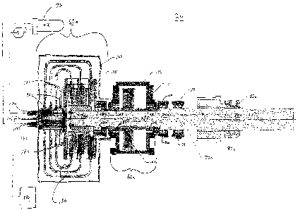
As indicated in FIG. 3 and more fully shown in FIG. 4A, which is a sectional
elevation along
section line AA of FIG. 3 and through the port clutch 65a, port gear reducer
60a, and outer end of
the port drive shaft 70a, the outer end portion of each drive shaft 70a, 70b
passes through the
primary gear reducer 60a, 60b and terminates within the clutch 65a, 65b. As
shown in FIG. 4A, the
primary gear reducer 60a includes a housing 100, a drive gear 105, a reducer
output shaft 110,
-6-
CA 02549877 2006-06-13
WO 2005/072309 PCT/US2005/002220
support bearings 115 for supporting the reducer output shaft 110 off of the
housing 100, and support
bearings 120 for supporting the reducer output shaft 110 off of the drive
shaft 70a.
As indicated in FIG. 4A, the drive shaft 70a is supported by the support
bearings 75 and is
coaxially, rotatably displaceable within the reducer output shaft 110 when the
clutch 65a is not fully
engaged. The reducer output shaft 110 is rotatably displaceable within the
housing 100 and
supported by the support bearings 115, 120. The drive gear 105 is coaxially
mounted on the reducer
output shaft 110 and transmits the power from the electric motor 45a, via the
power shaft 50a, to the
reducer output shaft 110. As will be explained in greater detail later in this
specification, the power
is then transmitted from the reducer input shaft 110 to the drive shaft 70a to
a greater or lesser
degree, depending on the degree of clutch engagement.
As illustrated in FIG. 4A, in one embodiment, the clutch 65a includes a clutch
housing 125, a
swivel assembly 130, a coolant inlet 135, a coolant outlet 140, a main
hydraulic or pneumatic control
pressure line 145, coolant lines 150, and branch hydraulic or pneumatic
control pressure lines 190.
In one embodiment, where the each clutch 65a, 65b is a disk or axial type
clutch, each clutch 65a,
65b will also include pressure plate friction surfaces 155 and clutch discs
160. In one embodiment, a
clutch guard 165 encloses all of the aforementioned components of the clutches
65a, 65b, except the
pressure line 145 and the coolant inlet 135 and outlet 140. The clutch housing
125 is secured to the
reducer output shaft 110 and is coaxially, rotatably displaceable about the
drive shaft 70a when the
clutch 65a is not fully engaged. The swivel assembly 130 is secured to the
clutch housing 125.
As indicated in FIG. 4A, the clutch housing 125 supports pressure plate
friction surfaces 155
that are parallel to each other, extend radially inward from the clutch
housing 125, and are secured to
the clutch housing 125. The clutch discs 160 are mounted on the end portion of
the drive shaft 70a,
are parallel to each other, and radially extend outward from the shaft's outer
circumference. Each
clutch disc 160 is sandwiched between a pair of pressure plate friction
surfaces 155. When the
pressure plate friction surfaces 155 are hydraulically or pneumatically
actuated by a hydraulic or
pneumatic engagement system 170, they engage the clutch discs 160.
When the pressure plate friction surfaces 155 are less than fully engaged, the
clutch discs 160
may rotatably displace relative to the friction surfaces 155, if a torque
exerted on the drive shaft 70a
exceeds the frictional force between the friction surfaces 155 and the clutch
discs 160. The drive
shaft 70a would then rotatably displace relative to the reducer output shaft
110.
Conversely, when the pressure plate friction surfaces 155 are fully engaged
such that the
torque exerted on the drive shaft 70a does not exceed the frictional force
between the friction
-7-
CA 02549877 2006-06-13
WO 2005/072309 PCT/US2005/002220
surfaces 155 and the clutch discs 160, the clutch discs 160 are prevented from
rotatably displacing
relative to the friction surfaces 155 and, as a result, the drive shaft 70a
does not rotatably displace
relative to the reducer output shaft 110. Consequently, the drive shaft 70a
and the reducer output
shaft 110 rotate together as one shaft.
As shown in FIG. 4A, the coolant inlet 135 and coolant outlet 140 are
connected to the
swivel assembly 130 to circulate coolant from the cooling system 175 through
the clutch housing
125 via the coolant lines 150. The coolant absorbs and removes heat generated
at the friction
surfaces 155. In one embodiment, the fluid coolant is water. In other
embodiments, the coolant will
be oil, air or other types of fluids.
As illustrated in FIG. 4A, the hydraulic or pneumatic control pressure line
145 runs from the
hydraulic or pneumatic actuation system 170 to a connection point on the
swivel assembly 130,
which is secured to the clutch housing 125. The branch hydraulic or pneumatic
lines 190 are in fluid
communication with the main hydraulic or pneumatic control pressure line 145
and run from the
swivel assembly 130 to the clutch housing 125. The branch hydraulic or
pneumatic lines 190 actuate
the friction surfaces 155. Other actuation systems based on magnetic,
mechanical or other actuation
methods may also be used.
While FIG. 4A depicts one embodiment of the invention where the drive shaft
70a is
coaxially positioned within the reducer output shaft 110, the friction
surfaces 155 extend radially
inward, and the clutch discs 160 extend radially outward, those skilled in the
art will realize that
other configurations of the invention may be developed without departing from
the spirit of the
invention.
For example, as illustrated in FIG. 4B, which is a sectional elevation similar
to FIG. 4A,
except of an alternative embodiment, the port clutch 65a and the port gear
reducer 60a have reversed
positions and the drive shaft 70a is no longer coaxially within the reducer
output shaft 110.
Furthermore, the clutch discs 160 extend radially inward from the drive shaft
70a or, that is to say,
an extension of the drive shaft 70a, and the friction surfaces 155 extend
radially outward from the
reducer output shaft 110, or in other words from a clutch housing 125 mounted
on the output shaft
110.
As shown in FIG. 4B, the coolant inlet 135, coolant outlet 140, and main
hydraulic or
pneumatic control pressure line 145 connect to a swivel assembly 130 on the
end of the output shaft
110. A branch hydraulic or pneumatic line 190 leads from the swivel assembly
130, through the
output shaft 110, and to the friction surfaces 155. Coolant supply and return
lines 150 run from the
-8-
CA 02549877 2006-06-13
WO 2005/072309 PCT/US2005/002220
coolant inlet 135 and outlet 140, through the output shaft 110, and to the
friction surfaces 155. Like
the embodiment illustrated in FIG. 4A, the gear reducer 60a causes the output
shaft 110 to rotate,
which causes the drive shaft 70a to rotate to a greater or lesser degree,
depending on the degree of
clutch engagement.
To illustrate another embodiment of the invention, reference is now made to
FIG. 4C, which
is a sectional elevation similar to FIG. 4A, except of an alternative
embodiment, wherein the port
clutch 65a and the port gear reducer 60a have reversed positions and the drive
shaft 70a is no longer
coaxially within the reducer output shaft 110. As shown in FIG. 4C, the clutch
discs 160 extend
radially outward from the drive shaft 70a, and the friction surfaces 155
extend radially inward from
the clutch housing 125, which is attached to the end of the output shaft 110.
As illustrated in FIG. 4C, the coolant inlet 135, coolant outlet 140, and main
hydraulic or
pneumatic control pressure line 145 connect to a swivel assembly 130 on the
end of the output shaft
110. A branch hydraulic or pneumatic line 190 leads from the swivel assembly
130, through the
output shaft 110, and to the friction surfaces 155. Coolant supply and return
lines 150 run from the
coolant inlet 135 and outlet 140, through the output shaft 110, and to the
friction surfaces 155. Like
the embodiment illustrated in FIG. 4A, the gear reducer 60a causes the output
shaft 110 to rotate,
which causes the drive shaft 70a to rotate to a greater or lesser degree,
depending on the degree of
clutch engagement.
To illustrate another embodiment of the winching system 2 of the subject
invention,
reference is now made to FIG. 3A, which is a schematic plan view of an
alternative embodiment of
the winching system 2. As shown in FIG. 3A, a power shaft 50 extends between a
motor 45 and a
gear box 60. A brake 55 is located along the power shaft 50. A first shaft 70
extends between the
gear box 60 and a clutch 65.
As shown in FIG. 4D, which is a sectional elevation taken along section line
BB of FIG. 3A
and through the clutch 65 and outer end of the first shaft 70, in extending
into the clutch 65, the first
shaft 70 is coaxially surrounded by a second shaft 110 and a first gear 105
mounted on the second
shaft 110. In one embodiment, a clutch housing 125 radially extends from the
second shaft 110.
Pressure plate friction surfaces 155 are mounted on the clutch housing 125 and
configured to engage
clutch discs 160 that radially extend from the first shaft 70.
As can be understood from FIG. 3A, the first gear 105 drives a second gear
106, which is
mounted on a third shaft 111. A fourth gear 113 is coaxially pivotally mounted
on the third shaft
111 and in engagement with a drum gear 114 on the winch drum 10. The fourth
gear 113 is brought
-9-
CA 02549877 2006-06-13
WO 2005/072309 PCT/US2005/002220
into engagement with the third shaft 111 via a jaw clutch 85 arrangement as
previously described in
this Detailed Description. When the fourth gear 113 is engaged with the third
shaft 111, it will drive
a drum gear 114 and, as a result, the winch drum 10.
To discuss the function of the load control power transmission 20 and its
components,
reference is now made to FIGS. 3, 4A and 5. FIG. 5 is a flow diagram
illustrating the function of the
transmission 20. In operation, the winch operator sets the winch load limit at
an operator's control
panel 180 (block 500). In other words, the operator sets the clutch 65a, 65b
such that the clutch
discs 160 will not rotatably displace relative to the friction surfaces 155,
unless the torque imposed
on the clutch 65a, 65b by the load in the wire rope 4 exceeds the frictional
force between the friction
surfaces 155 and the clutch discs 160. In one embodiment, the winch load limit
will be based on a
percentage of the structural load limit of the winch or a component of the
winch (e.g., the structural
load limit of the wire rope).
The operator then causes the winch to perform a payout or haul-in operation or
causes the
winch to hold a load in place. If the actual load in the wire rope 4 does not
exceed the set load limit
(block 510), then there is no relative motion between the clutch discs 160 and
the friction surfaces
155 (block 520). As a result, there is no relative motion between the drive
shaft 70a, 70b and the
reducer output shaft 110, and these shafts operate as one shaft (block 520).
If the actual load in the wire rope exceeds the set load limit (block 510),
then there is relative
motion between the clutch discs 160 and the friction surfaces 155, because the
clutch discs 160 slip
(block 530). Consequently, there is relative motion between the drive shaft
70a, 70b and the reducer
output shaft 110 (block 520). This situation may arise, for example, during a
payout or haul-in
procedure when a large wave causes the vessel 1 to surge upwards, suddenly
decreasing the slack in
the wire rope and causing the wire rope load to peak. Once the actual load in
the wire rope returns
below the set load limit (block 510) (e.g., the vessel 1 rides down the wave
and the slack in the wire
rope increases), the friction surfaces 155 relock on the clutch discs 160 and
the relative motion
between the drive shaft 70a, 70b and the reducer output shaft 110 ceases
(i.e., the these shafts again
operate as one shaft) (block 520).
The load control power transmission 20 facilitates dynamic, high speed/high
horsepower
wire rope payout by providing two modes for dissipating the energy generated
during the dynamic
payout process. In the first mode, during a dynamic payout, the load control
power transmission 20
generates energy via a motor 45a, 45b and the energy is dissipated at an
energy dissipation system
185 connected to the motor 45a, 45b. For example, in one embodiment, the
energy is generated at
-10-
CA 02549877 2006-06-13
WO 2005/072309 PCT/US2005/002220
an electric motor 45a, 45b and the energy is dissipated at an electrical load,
such as a resistor bank
185, electrically connected to the electrical motor 45a, 45b. In the second
mode, during a dynamic
payout, the load control power transmission 20 generates energy via both an
electric motor 45a, 45b
and a clutch 65a, 65b, and the energy is dissipated via the resistor bank 185
coupled to the motor
45a, 45b and a cooling system 180 coupled to the clutch 65a, 65b.
As explained above, in one embodiment of the first mode, the dynamic payout
energy may
be dissipated at an electrical load (e.g., resistor bank 185) coupled to an
electric motor 45a, 45b.
However, in another embodiment of the first load, wherein the electrical motor
45a, 45b and the
electrical load 185 are replaced with a hydraulic motor coupled to a hydraulic
system, the dynamic
payout energy is dissipated via the hydraulic system. In either case, in the
second mode, the energy
generation/dissipation method of the first mode (i.e., the electric
motor/electrical load combination
or the hydraulic motor/hydraulic system combination) is combined with the
energy
generation/dissipation capability of the fluid cooled clutch 65a, 65b coupled
to the cooling system
180.
FIG. 6 is a flow diagram illustrating the dynamic payout process. In
operation, the winch
operator uses the operator's control panel 180 to set a transition point
wherein the load control power
transmission 20 shifts from the first mode to the second mode (block 600). In
other words, the
transition point determines when the energy generation/dissipation
responsibilities shifts from being,
generally speaking, the responsibility of the primary energy
generation/dissipation system (i.e., the
electric motor/resistor bank combination) to being shared between the primary
energy
generation/dissipation system and the supplemental energy
generation/dissipation system (i.e., the
clutch/cooling system combination).
In one embodiment, the transition point maybe based on a percentage of the
resistor bank
capacity. For example, in one embodiment, the setting is 66% of the maximum
resistor bank
dissipation capacity.
In one embodiment, the transition point may be based on a predetermined
electric motor
speed, winch drum speed, and/or torque perceived by the motor. For example, in
one embodiment,
the predetermined electric motor speed and/or torque maybe based on a
percentage of the maximum
payout motor speed and/or torque.
Once the transition point has been set (block 600), the operator causes the
winch to perform a
dynamic payout operation. If the power generated by the electric motor 45a,
45b does not exceed
the setting (e.g., 66% of the maximum resistor bank dissipation capacity or a,
predetermined payout
-11-
CA 02549877 2006-06-13
WO 2005/072309 PCT/US2005/002220
motor speed) (block 610), then the electric motor 45a, 45b continues to handle
the dynamic payout
forces by itself (i.e., the electric motor/resistor bank combination is,
generally speaking, responsible
for the generation and dissipation of all the dynamic payout energy) and there
is no relative motion
between the clutch discs 160 and the friction surfaces 155 (block 620). As a
result, there is no
relative motion between the drive shaft 70a, 70b and the reducer output shaft
110, and these shafts
operate as one shaft (block 620). Thus, when the load control power
transmission 20 is operating in
the first mode during a dynamic payout, the speed of the winch drum is
controlled by the braking
effect of the motor 45a, 45b and associated electrical load (e.g., resistor
bank 185).
If the power regenerated by the electric motor 45a, 45b exceeds the setting
(e.g., 66% of the
maximum resistor bank regeneration dissipation capacity or a predetermined
payout motor speed
and/or torque) (block 610), then the load control power transmission 20
transitions to the second
mode and the excess percentage of the resistor bank capacity or the motor
speed and/or torque is
accommodated by the fluid cooled clutch 65a, 65b (block 630). Specifically,
the clutch discs 160
begin to slip allowing relative motion between the clutch discs 160 and the
friction surfaces 155
(block 630). As a result, there is relative motion between the drive shaft
70a, 70b and the reducer
output shaft 110, which, in one embodiment, allows the motor 45a, 45b to slow
and decreases the
power being sent to the resistor bank 185 (block 630). In another embodiment,
relative motion
between the drive shaft 70a, 70b and the output shaft 110 at least prevents
the motor speed and/or
the power being sent to the resistor bank from increasing further.
The heat generated by the slipping clutch discs 160 is carried away by the
cooling system
175 (block 630). Thus, when the load control power transmission 20 is
operating in the second
mode during a dynamic payout, the speed of the winch drum is controlled by the
braking effects of
the motor 45a, 45b and associated electrical load (e.g., resistor bank 185)
and the slipping discs 160
of the fluid cooled clutch 65a, 65b. Also, in the second mode, the relative
motion between the shafts
70, 110 allows the speed of the payout to be maintained, although the electric
motor 45a, 45b has
been allowed to slow or at least the motor's speed and/or torque has not
continued to increase.
Once the power to be dissipated during the dynamic payout process decreases to
a level that
does not exceed the setting (block 610), the friction surfaces 155 fully
engage the clutch discs 160 to
stop the relative motion between these aspects of the clutch 65a, 65b (block
620). At the same time,
the electric motor 45a, 45b, if necessary, speeds up to match the payout
speed, and the resistor bank
185 again, generally speaking, becomes responsible for dissipating all of the
power being generated
by the dynamic payout (block 620).
-12-
CA 02549877 2006-06-13
WO 2005/072309 PCT/US2005/002220
In one embodiment, the dynamic payout power being generated by the electric
motor 45a,
45b and sent to the resistor bank 185 is monitored via power sensor means as
are known in the art.
As the power increases, additional resistors are brought on line (i.e., the
electrical load is increased
incrementally). Once, the transition point (i.e., a percentage of the
electrical load capacity) has been
reached, the clutch 65a, 65b is progressively released and relative rotational
displacement between
the drive shaft 70a, 70b and the output shaft 110 progressively increases. As
the dynamic payout
process continues, the power being sent to the electrical load 185 is
continuously monitored and the
clutch will be adjusted accordingly.
In one embodiment while the system is operating in the second mode, if the
power to the
electrical load begins to decrease, the power sensors will determine this as
an indication that the
overall dynamic payout power is decreasing. Consequently, the clutch 65a, 65b
will be actuated to
progressively decrease the rotational displacement between the drive and
output shafts - If the
monitoring system determines that the overall dynamic payout power has
decreased to a point that
does not exceed the transition point, then the system will begin to transition
to the first mode by
progressively actuating the clutch to progressively increase the torque
perceived by the electrical
motor until the system is fully operating in the first mode.
As explained above, in one embodiment, as the energy generated during the
dynamic payout
process causes the set percentage of maximum motor speed or electrical load
capacity to be
exceeded, the clutch 65a, 65b begins to slip and the cooling system 175 begins
to assume
responsibility for at least a portion of the necessary energy dissipation. In
other words, the energy
dissipation responsibilities transitions from being, generally speaking, the
responsibility of the
electrical motor 45a, 45b and its associated electrical load 185, to being at
least partially shared with
the clutch 65a, 65b and the cooling system 175.
However, the responsibilities and sequencing may be reversed. For example, the
energy
dissipation responsibilities could initially be, generally speaking, the
responsibility of the clutch 65a,
65b and the cooling system 175. When a set point associated with the clutch
(e.g., a percentage of
the maximum clutch speed or a percentage of the maximum cooling capacity of
the coaling system)
is exceeded, the electrical motor 45a, 45b and its associated electrical load
185 begin to assume at
least partial responsibility for energy dissipation.
In the event of an emergency stop or drum over-speed condition, the fluid
cooled clutch 65a,
65b is fully applied, along with the drum brakes and the electric motor brakes
55a, 55b, in a
controlled sequence. This provides maximum stopping power to the winch.
-13-
CA 02549877 2006-06-13
WO 2005/072309 PCT/US2005/002220
Although the present invention has been described with reference to preferred
embodiments,
persons skilled in the art will recognize that changes may be made in form and
detail without
departing from the spirit and scope of the invention.
-14-