Language selection

Search

Patent 2550040 Summary

Third-party information liability

Some of the information on this Web page has been provided by external sources. The Government of Canada is not responsible for the accuracy, reliability or currency of the information supplied by external sources. Users wishing to rely upon this information should consult directly with the source of the information. Content provided by external sources is not subject to official languages, privacy and accessibility requirements.

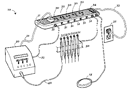
Claims and Abstract availability

Any discrepancies in the text and image of the Claims and Abstract are due to differing posting times. Text of the Claims and Abstract are posted:

  • At the time the application is open to public inspection;
  • At the time of issue of the patent (grant).
(12) Patent Application: (11) CA 2550040
(54) English Title: INTEGRATED DENTAL EQUIPMENT
(54) French Title: MATERIEL DENTAIRE INTEGRE
Status: Deemed Abandoned and Beyond the Period of Reinstatement - Pending Response to Notice of Disregarded Communication
Bibliographic Data
(51) International Patent Classification (IPC):
  • A61C 1/00 (2006.01)
(72) Inventors :
  • MAXWELL, RANDALL (United States of America)
  • GARROTT, CHARLES E. (United States of America)
(73) Owners :
  • DENTSPLY INTERNATIONAL INC.
(71) Applicants :
  • DENTSPLY INTERNATIONAL INC. (United States of America)
(74) Agent: SMART & BIGGAR LP
(74) Associate agent:
(45) Issued:
(86) PCT Filing Date: 2004-12-15
(87) Open to Public Inspection: 2005-07-07
Availability of licence: N/A
Dedicated to the Public: N/A
(25) Language of filing: English

Patent Cooperation Treaty (PCT): Yes
(86) PCT Filing Number: PCT/US2004/041997
(87) International Publication Number: WO 2005060858
(85) National Entry: 2006-06-16

(30) Application Priority Data:
Application No. Country/Territory Date
60/530,871 (United States of America) 2003-12-18

Abstracts

English Abstract


An integrated dental system (10) includes a power connector base (11) having a
plurality of electrical connectors (30) and a plurality of foot pedal
connectors (31). A plurality of handpieces (12) are connected via their
standard control units (20) to both the electrical connectors (30) and the
foot pedal connectors (31). A single foot pedal (13) is employed to
selectively operate and actuate each handpiece (12) as desired.


French Abstract

L'invention concerne un système dentaire intégré (10) comprenant une base d'alimentation (11) comportant une pluralité de connecteurs électriques (30) et une pluralité de connecteurs de commandes à pied (31). Une pluralité de pièces à main (12) sont connectées par l'intermédiaire de leurs unités de commande standard (20) aux connecteurs électriques (30) et aux connecteurs de commandes à pied (31). Une commande à pied unique (13) est utilisée pour actionner sélectivement chaque pièce à main (12).

Claims

Note: Claims are shown in the official language in which they were submitted.

What is claimed is:
1. An integrated dental equipment system comprises a power connector base;
said
power connector base includes a plurality of electrical outlets and a
plurality of foot
pedal connectors; a foot pedal is operatively and electrically connected
through said
power connector strip and through said foot pedal connectors such that said
foot pedal
is in operative communication to a plurality of handpieces connected to said
power
connector strip.
4

Description

Note: Descriptions are shown in the official language in which they were submitted.


CA 02550040 2006-06-16
WO 2005/060858 PCT/US2004/041997
INTEGRATED DENTAL EQUIPMENT
Tech~zical Field
[0001] The present invention is directed toward the integration of dental
equipment.
More particularly the invention provides for the operation of different dental
equipment that makes use of single common components such as power supply,
foot
pedal controls and the like.
Bachg~ound of the Iuvesitiou
[0002] With advances in dental technology, dental offices have become
cluttered
with a large number of different instruments and pieces of equipment. Doctors
are
frustrated with multiple foot pedals and cords cluttering the operatory.
Competition
for counter space, or "footprint", from various dental equipment items such as
motors,
ultrasonic units, obturation devices, apex locators, prophylaxis equipment,
drills,
handpieces and the lilce (all such equipment being generally referred to as
handpieces
herein) is an increasing problem in the industry. A growing interest in carts,
integrated operatory equipment, and rolling product organizers has been the
result.
[0003] A need exists therefore for a simple and efficient means to integrate a
number of such items such that a common number of components may be employed,
replacing multiple such components with a single, shared component.
Summary of the Inven.tiou
[0004] An integrated dental system therefore, includes for example, a common
power source, a common actuating foot pedal, and common handpiece organizer or
other cormnon dental equipment organizer.
Bfief Desctiptiou of tlae Drawifags
[0005] The drawing figure shows a partially schematic view of an integrated
dental
equipment system according to the present invention.

CA 02550040 2006-06-16
WO 2005/060858 PCT/US2004/041997
Preferred Ernbodinaent for' Carr~irzg Out tlae Invention
[0006] In the drawing, an integrated dental equipment system according to the
present invention is generally designated by the numeral 10. Integrated system
10
includes a power comZector base unit 1 l, a plurality of handpieces 12, and an
actuating foot pedal 13. The present invention is intended to provide a common
power supply and foot pedal control for a plurality of handpieces 12. The
exact
nature of the handpieces 12 is not critical to the operation of the invention.
Therefore,
handpieces 12 can be any of those discussed above, or any similar equipment.
Each
dental handpiece 12 has a control unit 20, which is unique to that handpiece.
As is
common, each control unit 20 has an electrical connection 21 to an electrical
power
supply, and a foot pedal connection 22. It has been the practice prior to the
present
invention, that each control unit 20 was required to have its own electrical
connection
21 to a separate power supply or outlet, and foot pedal cable connection 22 to
a
separate foot pedal (not shown).
[0007] According to the present invention, connector base 11 provides both
electrical power and foot pedal connections for each of a plurality of control
units 20
and handpieces 12. Therefore, connector base 11 includes a plurality of
electrical
outlets 30 and a preferably equal plurality of~foot pedal connectors 31. As
will be
appreciated, electrical outlets 30 will be the standard electrical outlet
employed in the
general geographic area wherein the system 10 is employed. Preferably, each
electrical outlet 30 is grounded. Therefore, connector 21 is a simple power
cord from
the control unit 20 plugged into the electrical outlet 30: Connector base 11
is in turn
connected to a standard power supply or wall outlet 32. This connection
through a
power cord 33 supplies electrical power to the connector base 11. A universal
on/off
switch 34 is provided wherein electrical power to the entire comiector base 11
can be
turned on or off as desired.
[0008] Foot pedal connectors 31 are configured to be unique to a given foot
pedal
cable connection 22 of the individual control unit 20 for a given handpiece
12.
Therefore, each of the connectors 31 will vary according to the equipment
employed
by the end user. This equipment will also vary according to the manufacturer
supplying the handpiece 12 and its associated control unit 20.
[0009] Electrically connected to connector base 11 is a foot pedal 13. Foot
pedal 13
is operatively and electrically connected through connector base 11 to each of
the
2

CA 02550040 2006-06-16
WO 2005/060858 PCT/US2004/041997
individual foot pedal connectors 31 such that actuating foot pedal 13 causes
an
individual handpiece 12 to be actuated. Further, each individual handpiece 12
is also
controlled by its control unit 20 in its standard manner. A given handpiece 12
is
connected to its control unit 20 by its standard control cord 40.
[0010] Therefore, in use, it will be understood that a control unit 20 has an
electrical
connection 21, which is connected or "plugged" into an electrical outlet 30 of
the
connector base 11. Further, a foot pedal cable connection 22 rather than being
connected directly to an actuating foot pedal, is instead connected to a foot
pedal
connector 31 on the connector base 11. Foot pedal 13 is electrically and
operatively
comlected through foot pedal coimectors 31 to the control unit 20 such that
the
handpiece 12 may be actuated by foot pedal 13. It will be appreciated
therefore, that a
plurality of handpieces 12 each connected to its own control unit 20 and
connected to
connector base 11 as described, can each individually be operated or actuated
by foot
pedal 13. Common electrical power is supplied through connector base 11 from
wall
outlet 32.
[0011] A common cradle or organizer 50 may also be included. Cradle 50 may be
a
desk cradle, a cart, a hanging cradle connected to other equipment, or the
like. Cradle
50 may include on/off components (not shown) such that when a handpiece 12 is
removed from cradle 50 its control unit 20 is actuated such that foot pedal 13
can then
be used to control handpiece 12.
[0012] Therefore, it is clear that an integrated dental system according to
the present
invention provides for a common power supply and a common actuating means such
as a foot pedal to a plurality of otherwise standard dental handpieces 12. By
"handpiece" it is understood to mean any of the various commonly employed
dental
equipment pieces standard in the dental industry. These include without
limitation,
those discussed herein above. The invention has been exemplified with
reference to
the attached drawings for illustrative purposes only. All of the various
embodiments
within the scope of the invention have not necessarily been discussed but will
be
evident to one of ordinary skill in the art. The scope of the invention shall
be limited
only by the claims as may be provided herein.

Representative Drawing
A single figure which represents the drawing illustrating the invention.
Administrative Status

2024-08-01:As part of the Next Generation Patents (NGP) transition, the Canadian Patents Database (CPD) now contains a more detailed Event History, which replicates the Event Log of our new back-office solution.

Please note that "Inactive:" events refers to events no longer in use in our new back-office solution.

For a clearer understanding of the status of the application/patent presented on this page, the site Disclaimer , as well as the definitions for Patent , Event History , Maintenance Fee  and Payment History  should be consulted.

Event History

Description Date
Application Not Reinstated by Deadline 2008-12-15
Time Limit for Reversal Expired 2008-12-15
Deemed Abandoned - Failure to Respond to Maintenance Fee Notice 2007-12-17
Letter Sent 2007-06-01
Inactive: Single transfer 2007-05-01
Correct Applicant Request Received 2007-05-01
Inactive: Courtesy letter - Evidence 2006-08-29
Inactive: Cover page published 2006-08-28
Inactive: Notice - National entry - No RFE 2006-08-23
Application Received - PCT 2006-07-18
National Entry Requirements Determined Compliant 2006-06-16
Application Published (Open to Public Inspection) 2005-07-07

Abandonment History

Abandonment Date Reason Reinstatement Date
2007-12-17

Maintenance Fee

The last payment was received on 2006-07-04

Note : If the full payment has not been received on or before the date indicated, a further fee may be required which may be one of the following

  • the reinstatement fee;
  • the late payment fee; or
  • additional fee to reverse deemed expiry.

Please refer to the CIPO Patent Fees web page to see all current fee amounts.

Fee History

Fee Type Anniversary Year Due Date Paid Date
Basic national fee - standard 2006-06-16
MF (application, 2nd anniv.) - standard 02 2006-12-15 2006-07-04
Registration of a document 2007-05-01
Owners on Record

Note: Records showing the ownership history in alphabetical order.

Current Owners on Record
DENTSPLY INTERNATIONAL INC.
Past Owners on Record
CHARLES E. GARROTT
RANDALL MAXWELL
Past Owners that do not appear in the "Owners on Record" listing will appear in other documentation within the application.
Documents

To view selected files, please enter reCAPTCHA code :


To view images, click a link in the Document Description column. To download the documents, select one or more checkboxes in the first column and then click the "Download Selected in PDF format (Zip Archive)" or the "Download Selected as Single PDF" button.

List of published and non-published patent-specific documents on the CPD .

If you have any difficulty accessing content, you can call the Client Service Centre at 1-866-997-1936 or send them an e-mail at CIPO Client Service Centre.


Document
Description 
Date
(yyyy-mm-dd) 
Number of pages   Size of Image (KB) 
Drawings 2006-06-16 1 27
Description 2006-06-16 3 164
Claims 2006-06-16 1 13
Abstract 2006-06-16 2 71
Representative drawing 2006-08-25 1 19
Cover Page 2006-08-28 1 46
Notice of National Entry 2006-08-23 1 193
Courtesy - Certificate of registration (related document(s)) 2007-06-01 1 107
Courtesy - Abandonment Letter (Maintenance Fee) 2008-02-11 1 176
PCT 2006-06-16 3 91
Correspondence 2006-08-23 1 26
Correspondence 2007-05-01 1 45