Note: Descriptions are shown in the official language in which they were submitted.
CA 02550266 2008-06-12
78543-236
DEPLOYABLE ZONAL ISOLATION SYSTEM
FIELD OF THE INVENTION
[0002] The present invention relates in general to wellbore
operations and more particular to a system for using a
deployable isolation assembly to isolate selected zones in a
wellbore.
BACKGROUND
[0003] Wellbores are often drilled through and completed for
production and/or injection in multiple formations or zones
of formations. Commonly, during the life of the wellbore it
is desirable or necessary to isolate one or more of the
zones. Prior systems isolation systems often require
rigging up to isolate the desired zone. Additionally, often
the prior art isolation systems result in a significant
reduction in the flow path through the completed section of
the well.
[0004] It is therefore a desire to provide a simple, easily
deployable and stackable zonal isolation solution.
1
CA 02550266 2008-01-16
78543-236
SUMMARY OF THE INVENTION
[0005] A deployable zonal isolation system and method for
isolating zones in a wellbore is provided. In one
embodiment, a method of providing zonal isolation in a
wellbore completion includes the steps of identifying an
anticipated zone for isolation in a wellbore before
completing the wellbore; selecting, before completing the
wellbore, a completion assembly and a cooperative deployable
isolation assembly to isolate the anticipated zone(s);
completing the wellbore with the selected completion
assembly; and connecting the selected deployable isolation
assembly in the selected completion assembly to isolate the
anticipated zone.
[0005a] According to one aspect of the present invention,
there is provided a method of providing zonal isolation in a
wellbore completion, the method comprising the steps of:
identifying an anticipated zone for isolation in a wellbore
before completing the wellbore; selecting, before completing
the wellbore, a completion assembly and a cooperative
deployable isolation assembly to isolate the anticipated
zone; completing the wellbore with the selected completion
assembly; and connecting the selected deployable isolation
assembly in the selected completion assembly to isolate the
anticipated zone.
[0005b] According to another aspect of the present
invention, there is provided a method of providing zonal
isolation in a wellbore completion, the method comprising the
steps of: identifying an anticipated zone for isolation in a
wellbore before completing the wellbore; selecting, before
completing the wellbore, a completion assembly adapted for
accepting a deployable isolation assembly for isolating the
anticipated zone for isolation after completion of the
2
CA 02550266 2008-01-16
78543-236
wellbore; providing the deployable isolation device for the
selected completion assembly, the deployable isolation device
having a mandrel having an internal bore and a swellable
material disposed on the exterior of the mandrel; completing
the wellbore with the selected completion assembly;
positioning the deployable isolation assembly in the selected
completion system proximate the anticipated zone for
isolating the zone; and sealing flow from the anticipated
zone at the interior of the selected completion assembly.
[0005c] According to still another aspect of the present
invention, there is provided a method of providing zonal
isolation in a wellbore completion, the method comprising the
steps of: identifying an anticipated zone for isolation in a
wellbore before completing the wellbore; selecting, before
completing the wellbore, a completion assembly having a flow
section adjacent to the anticipated zone and a receiver
adapted to position a deployable isolation assembly for
isolating the anticipated zone after completion of the
wellbore; providing the deployable isolation device for the
selected completion assembly, the deployable isolation device
having a mandrel having an internal bore, a swellable
material disposed on the exterior of the mandrel and a
locating device matable with the receiver to position the
swellable material substantially across the anticipated zone;
completing the wellbore with the selected completion assembly
and gravel packing; positioning the deployable isolation
assembly in the selected completion system proximate the
anticipated zone for isolating the zone; and sealing flow
from the anticipated zone at the interior of the selected
completion assembly by expanding the swellable material in
response to fluids in the wellbore.
[0006] The foregoing has outlined the features and
technical advantages of the present invention in order that
2a
CA 02550266 2008-01-16
78543-236
the detailed description of the invention that follows may be
better understood. Additional features and advantages of the
invention will be described hereinafter which form the
subject of the claims of the invention.
2b
CA 02550266 2008-01-16
78543-236
BRIEF DESCRIPTION OF THE DRAWINGS
[0007] The foregoing and other features and aspects of the present invention
will be best
understood with reference to the following detailed description of a specific
embodiment of the
invention, when read in conjunction with the accompanying drawings, wherein:
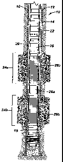
[0008] Figure 1 is a schematic of a wellbore completed with an embodiment of
the completion
assembly of the present invention;
[0009] Figure 2 is an exploded view of an embodiment of the deployable zonal
isolation system;
and
[0010] Figure 3 is a perspective view of a wellbore completed with another
embodiment of the
isolation assembly of the present invention.
3
CA 02550266 2008-01-16
78543-236
DETAILED DESCRIPTION
[0011] Refer now to the drawings wherein depicted elements are not necessarily
shown to scale
and wherein like or similar elements are designated by the same reference
numeral through the
several views.
100121 As used herein, the terms "up" and "down"; "upper" and "lower"; and
other like terms
indicating relative positions to a given point or element are utilized to more
clearly describe
some elements of the embodiments of the invention. Commonly, these terms
relate to a
reference point as the surface from which drilling operations are initiated as
being the top point
and the total depth of the well being the lowest point.
[0013] Figure 1 is a schematic of a wellbore 12 completed with an embodiment
of a selected
completion assembly 14 of deployable zonal isolation system of the present
invention, generally
designated by the numeral 10. In the illustrated embodiment, wellbore 12 is a
gravel pack
completion including casing 16. As is well known in the art, gravel 18 is
disposed in annulus 20
between casing 16 and completion assembly 14 by pumping a gravel 18 laden
slurry through
cross-over 22. It should be noted that although the invention is illustrated
with a cased gravel
pack completion, the invention is applicable for open hole gravel packing and
non-gravel packed
completions.
[0014] Wellbore 12 is drilled into the earth having multiple formation zones
24 of interest. In
Figure 1, wellbore 12 includes a first zone 24a and a second zone 24b from
which it is desired to
produce hydrocarbons. In the present example, prior to the completion of
wellbore 12 it is
anticipated that during the production life of wellbore 12 that water will
first encroach at zone
4
CA 02550266 2008-01-16
78543-236
24b and will encroach later in time at zone 24a. Thus, completion assembly 14
is selected and
design for isolating zones 24a and 24b during the production life of the well.
[0015] Flow sections 28 are positioned within completion assembly 14 so as to
be positioned
adjacent the respective formation zones 24 upon completion of wellbore 12. In
anticipation of
isolating flow sections 28, one or more receivers 26 are incorporated into
completion assembly
14. As illustrated, a receiver 26b is positioned below flow section 28b and a
receiver 26a is
positioned between flow sections 28a and 28b. Each of the receivers 26 is
adapted to position an
isolation assembly 30 (Figure 3) proximate a respective flow section 28 and
flow zone 24. As
will be further understood with the following description, completion assembly
14 may include a
single receiver 26 for isolating multiple flow sections 28 over the life of
the well.
[0016] Figure 2 is an illustration of deployable isolation system 10 including
selected completion
assembly 14 and deployable isolation assembly 30. Completion assembly 14 is
selected for a
specific wellbore 12 and is adapted for accepting a cooperative deployable
isolation assembly 30
to isolate a zone 24 during the production life of the well.
[0017] Flow sections 28 permit flow of fluid from the exterior of completion
assembly 14 to its
interior conduit 32. Flow sections 28 may be constructed in many manners
and/or comprise
various apparatus. Examples of flow sections 28, without limitation, include
tubulars to be
perforated at completion, pre-perforated tubulars, slotted liners and the
various screen
configurations.
CA 02550266 2008-01-16
78543-236
[0018] Completion assembly 14 further includes one or more receivers 26.
Receivers 26 are
adapted to position deployable isolation assembly 30 proximate to flow section
28 which is
anticipated to be isolated. The distance between each receiver 26 and a
respective flow section
28 is noted for the selected isolation assembly 30. It is noted that
completion assembly 14 may
include other devices such as, but not limited to, valves and packers.
[0019] It should be noted that completion assembly 14 may comprise one
elongated perforated
tubular, wherein each flow section 28a and 28b is defined in relation to
formation flow zones 24a
or 24b or more specifically to portions of the formation that are expected to
require isolation. As
such, a single receiver 26 may be positioned for placement of a isolation
assembly 30 in an
isolation position of the lowest most flow section 28b. Then, over the
production life,
subsequent isolation assemblies may be stacked with the first isolation
assembly to progressively
isolate zones as they water out. Further, receivers 26 may be placed proximate
to one or more
anticipated flow sections 28 for positioning isolation assemblies 30.
[0020] Deployable isolation assembly 30 includes a mandrel 34 forming an
internal bore 36 and
a swellable material 38 disposed on its exterior. The length, diameter and
other physical
dimensions and properties of mandrel 34 and swellable material 38 are selected
for positioning
within interior 32 of selected completion assembly 14. Isolation assembly 30
may be deployed
via tubing, coiled tubing, slick line or wireline.
[0021] Isolation assembly 30 further includes a locating device 40 selected in
combination with
a receiver 26 in completion assembly 30. As shown in Figure 2, locating device
40 is a latching
collet matable with latch profile 26 of completion assembly 14. Other locating
devices 40, and
6
CA 02550266 2008-01-16
78543-236
cooperative receivers 26, may be utilized, such as, but not limited to, no-
gos, snap latches,
anchor latches and shearable anchor latches. A spacer 42 may be included in
isolation assembly
30 to accurately position it relative to a receiver 26 and its respective flow
section 28. It is noted
that locating device 40 may be positioned above or below swellable materia138
to correspond to
its respective receiver 26 and anticipated flow section 28 of completion
assembly 14.
[0022] Deployable isolation assembly 30 may further include a receiver
connector 44 adapted
for mating with a locating and anchoring device 40 of a subsequent isolation
assembly 30. In
this configuration, as described above, one or more isolation assemblies 30
may be stacked one
atop another to progressively isolate lengths of flow section 28. For example,
a first isolation
assembly 30 is run into completion assembly 14 and positioned via receiver 26b
at flow section
28b. Later in the production life, as flow section 28a produces water, a
subsequent isolation
assembly 30 may be run into completion assembly 14 and connected via locating
device 40 and
receiver connector 44 to isolate flow section 28a.
[0023] Swellable material 38 is a material that expands upon contact with
fluid in the wellbore.
Swellable material 28 may be of various compositions including, but not
limited to, nitrite,
neoprene, natural rubber, and AFLAS* In an initial position, swellable
material 38 has an outside
diameter of less than the internal diameter of the interior 32 of completion
assembly 14. Upon
being positioned within completion assembly 14 and contacting the fluid in
wellbore 12, material
38 expands to a sealing position. In the sealing position, swellable material
38 expands
outwardly from mandrel 34 to completion assembly 14 sealing the annulus
between the two
assemblies.
* Trade-mark
7
CA 02550266 2008-01-16
78543-236
[0024] With reference to Figures 1 and 2 an embodiment of a method of
providing zonal
isolation in a wellbore completion is described. Before completion of wellbore
12, the various
formation zones 24 of interest are identified. Formation zones 24 that are
anticipated to require
isolation during the life of the well are identified. For example, it is
anticipated that zone 24b
will produce water first and then at a later date zone 24a will produce water
and require isolation.
[0025] A completion assembly 14 is selected having flow sections 28a and 28b
corresponding to
flow zones 24a and 24b respectively. In one embodiment, a receiver 26b is
positioned in
completion assembly 14 at a known spacing below flow section 28b. A receiver
26a may also be
positioned at a known location between flow sections 28a and 28b for either
isolating flow
section 28a after flow section 28b or for isolating flow section 28a instead
of flow section 28b,
for example when flow zones 24a and 24b are different producing formations.
[0026] A deployable isolation assembly 30 for the selected completion assembly
14 is selected.
The selected deployable isolation assembly has a swellable material 38 with
dimensions suitable
for positioning in selected completion assembly 14 and of a length sufficient
to seal across
anticipated zone 24. A spacer 42 is selected of a length to position swellable
material 38 across
the desired flow section 28 relative to the selected receiver 26.
[0027] Wellbore 12 is completed with selected completion assembly 14. The
completion may be
open hole or include casing 16 has shown in Figure 1. If wellbore 16 is cased,
it is perforated at
the desired section. The completion may further include gravel packing.
Although the system of
the present invention may be used in non-gravel packed wells, it is
particularly suited and
beneficial in gravel pack completions.
8
CA 02550266 2008-01-16
78543-236
[0028] When it is desired to isolate anticipated zone 24b, such as due to
excessive water
production, selected isolation assembly 30 is deployed. Selected isolation
assembly 30 is run
into the interior 32 of completion assembly 14 via coiled tubing, slick line,
wire line or other
means. Locating device 40 is landed in the cooperative receiver 26b,
positioning swellable
materia138 adjacent to anticipated zone 24b and its respective flow section
28b.
[0029] Within a time prescribed by the particular swellable material 38 and
wellbore 12
conditions, swellable material 38 expands from its initial position to a
sealing position. In the
sealing position, swellable material 38 blocks fluid flow from the exterior of
completion
assembly 30 into interior 32 and into internal bore 36 of isolation assembly
30.
[0030] When it is desired to isolate zone 24a through flow section 28a a
subsequent isolation
assembly 30 is deployed. In one embodiment, the subsequent isolation assembly
30 is run into
completion assembly 14 and its locating device 40 is mated with receiver
connector 44 of the
preceding isolation assembly 30. In another method, the subsequent isolation
assembly 30 is run
into completion assembly 14 and connected via receiver 26a positioning it in a
isolation position
proximate flow section 28a and flow zone 24a.
[0031] Refer now to Figure 3, wherein another embodiment of deployable
isolation assembly 30
further includes an anchoring device 50. Anchoring device 50 engages
completion assembly 14
providing additional anchoring of assembly 30 when needed or desired.
[0032] In the illustrated embodiment, anchoring device 50 is an inflatable
packer positioned
above swellable isolation member 38. It should be noted that other anchoring
devices may be
9
CA 02550266 2008-01-16
78543-236
utilized. Anchor 50 may be positioned in various locations relative to
isolation member 38 to
secure isolation assembly 30 to completion assembly 14.
[0033] From the foregoing detailed description of specific embodiments of the
invention, it
should be apparent that a system and method for providing zonal isolation in a
wellbore that is
novel has been disclosed. Although specific embodiments of the invention have
been disclosed
herein in some detail, this has been done solely for the purposes of
describing various features
and aspects of the invention, and is not intended to be limiting with respect
to the scope of the
invention. It is contemplated that various substitutions, alterations, and/or
modifications,
including but not limited to those implementation variations which may have
been suggested
herein, may be made to the disclosed embodiments without departing from the
spirit and scope
of the invention as defined by the appended claims which follow.