Note: Descriptions are shown in the official language in which they were submitted.
CA 02550380 1997-11-26
CONVEYOR SYSTEM
BACKGROUND OF THE INVENTION
The present invention relates to a conveyor system. More particularly,
the present invention relates to a conveyor system for use in accepting one or
more product streams and formatting the product to match the format required
at the input of a packaging machine.
Conveyor systems are used for a wide range of purposes. One such
purpose is the formatting of one or more streams of product so that, for
example, the product spacing corresponds to the spacing needed for a
subsequent operation. Such conveyor systems are used, for example, to convert
one or two output streams of stacked or shingled meat from a slicing machine
into the format required by a packaging machine. Depending on the required
format, the conveyor must combine two or more separate streams into a single
output stream or multiply the streams into a larger number of output streams.
,Additionally, the conveyor must properly space the product along both the
length and the width of the conveyor to ensure compatibility with the
packaging
machine.
CA 02550380 1997-11-26
-2-
Conventional conveyor systems for changing the number of streams of
product usually include a simple flat belt conveyor and a series of fixed
kerbs or
built conveyors which guide the products in the lateral direction of the belt
conveyor to merge two streams into one or to multiply the number of streams.
Examples of these conventional conveying systems are described in FR-A-
2587007 and FR-A-2168967.
Conventional systems that have been provided specifically for handling
meat products include U.S. Patent No. 4,431,104 in which three successive
products from a stream coming from one direction are fed to a turning table on
which the direction of conveyance of the products is turned through 90
degrees,
so that, at the output of the turning table, the three successive products
form
three separate streams of product on an output conveyor. Another conveyor
system specifically intended to handle slices of meat product is shown in GB-A-
1546126 in which a single stream of product is fed via an overhead conveyor
and placed on top of pieces of card fed along a second conveyor underneath the
overhead conveyor with means being provided to synchronize the travel of the
product and the card so that the product is deposited on the card.
Another conveyor system specifically adapted for formatting meat
products is shown in U.S. Patent No. 4,846,336. The ' 336 patent is
purportedly directed to a conveyor system for positioning slices of meat by
converting M input streams of product into N output streams of products where
M is an integer greater than one and N is an integer not equal to M. The
system includes an input conveyor for conveying M input streams and an output
CA 02550380 1997-11-26
-3-
conveyor for conveying N output streams. It also includes a multi-element
strip
conveyor having its upstream input end arranged to receive products from an
input stream and having its downstream end arranged to continuously move
laterally throughout the formatting process to deposit products from the input
stream to form an output stream shifted laterally with respect to the input
stream.
The present inventors have recognized that the foregoing conveyor
system may experience significant limitations in high-speed operation. Such
high-speed operation is becoming increasingly necessary in view of the high-
speed meat slicing and packaging systems that are available.
CA 02550380 1997-11-26
-4-
BRIEF SUMMARY OF THE INVENTION
A conveyor system for accepting one or more streams of product input
and converting the one or more streams to a format that is suitable for
automatic
loading to a subsequent machine is disclosed. The conveyor system comprises
an input level shifting conveyor disposed to receive the one or more product
input streams: The level shifting conveyor is movable between a first upper
level position and second lower level position. An upper level strip conveyor
is
disposed to receive product from the input level shifting conveyor when the
input level shifting conveyor is moved to the first upper level position. The
upper levei strip conveyor includes an output end that is in a ftxed position
during formatting to direct product received by the upper level strip conveyor
to
a first lateral alignment position of the format. A lower level strip conveyor
is
disposed to receive product from the level shifting conveyor when the level
shifting conveyor is moved to the second lower level position. The lower level
strip conveyor includes an output end that is in a fixed position during
formatting to direct product received by the lower level strip conveyor to a
second lateral alignment position of the format. The second lateral alignment
position is different from the first lateral alignment position. An output
level
shifting conveyor is also used. The output level shifting conveyor is movable
between a first upper level position at which it indisposed to receive product
from the upper level strip conveyor and a second lower level at which it is
disposed to receive product from the lower level strip conveyor.
In accordance with various advantageous embodiments of the conveyor
CA 02550380 1997-11-26
-5-
system, the input level shifting conveyor comprises at least two adjacent
hinged
conveyors pivotable about a common axis and independently operable to direct
product to the upper and lower level strip conveyors. The lower level strip
conveyor likewise comprises at least two output ends disposed laterally from
one another and respectively associated with each of the at least two hinged
conveyors. The output level shifting conveyor of such an embodiment may
comprise a plurality of hinged conveyors that are pivotably movable about a
common axis. Each hinged conveyor is respectively associated with each of the
at least two output ends of the lower level strip conveyor.
Still further, the conveyor system includes first and second strip
conveyors. The first and second strip conveyors comprise a common input end
that is common to both of the first and second strip conveyors. A lateral
drive
is disposed to drive the common input end in a lateral direction. A first
output
portion terminates the output of the first strip conveyor and a second output
portion terminates the output of the second strip conveyor. A lateral
adjustment assembly is used for laterally adjusting the first and second
output
portions independent of one another. The first and second strip conveyors are
particularly useful in a conveyor system for accepting one or more streams of
product input and converting the one or more streams to a format that is
suitable for automatic loading to a subsequent machine.
Still further, the conveyor system includes a control system suitable for
driving the conveyor to provide 1-to-2, 1-to-3, 1-to-4, 2-to-2, 2-to-3, and 2-
to-4
product formats.
CA 02550380 1997-11-26
-6-
Still further, the conveyor system includes a modular stop assembly for
increasing the versatility of the conveyor system and render it readily re-
configurable for various product formats.
CA 02550380 1997-11-26
BRIEF DESCRIPTION OF THE SEVERAL
VIEWS OF THE DRAWINGS
FIG. 1 is a side view of a slicing/conveying/packaging system
incorporating a conveying system, shown here in cross-section, that is
constructed in accordance with one embodiment of the present invention.
FIG. 2 is a side cross-sectional view of the level shifting conveyors and
the strip conveyors of the embodiment of FIG.1.
FIG. 3 is a top view of the level shifting conveyors and the upper level
strip conveyors with certain sections in cross-sectional view.
FIG. 4 is a top view of the level shifting conveyors and the lower level
strip conveyors with certain sections in cross-sectional view.
FIG. 5 illustrates one embodiment of a lateral drive suitable for laterally
driving the input end of one of the strip conveyors.
FIGs. 6 and 7 illustrate one embodiment of the row staging conveyor of
the conveyor system of FIG. 1.
FIG. 8 is a side view of one embodiment of an output and reject
conveyor system suitable for use with the basic conveyor system of FIG. 1.
FIG. 9 is a top view of the output conveyor system of FIG. 8 with
certain portions thereof in cross-sectional view.
FIG. 10 is a side, cross-sectional view of one embodiment of an
accumulator conveyor illustrating the associated tensioning mechanism.
FIG. 11 is a top view of the tensioning mechanism of FIG. 10 with
i ,
CA 02550380 1997-11-26
_8_
certain sections thereof in partial cross-section.
FIGs. 12 and 13 illustrate one manner of providing the output conveyor
system of FIG. 8 with a pivotable output section.
FIG. 14 is a top view of the reject conveyor system of FIG. 8 with
certain sections thereof in cross-sectional view.
FIGs. 15 and 16 illustrate a further embodiment of a reject conveyor
system suitable for use with the system illustrated in FIG. 1.
FIGs. 17 - 22 illustrate several ways in which the conveyor system of
FIG. 1 can be operated to provide different product formats with different
product input streams.
FIG. 23 illustrates one embodiment of a control system architecture
suitable for use in controlling the operation of the conveyor system of FIG.
1.
FIGS. 24 and 25 illustrate placement and construction of various sensors
that may be used to detect the position of product as the product travels
through
the conveyor system.
CA 02550380 1997-11-26
-9-
DETAILED DESCRIPTION OF THE INVENTION
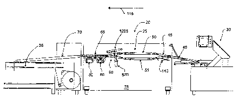
FIG. I illustrates a slicing/conveying/packaging system, shown
generally at 20 which utilizes a conveyor system, shown generally at 25,
constructed in accordance with one embodiment of the present invention. As
shown, the system 20 comprises a slicing machine 30, the conveyor system 25,
and a packaging machine 35. The slicing machine 30 may be, for example, a
high-speed slicing machine such as an S-180T"' available from FormaxT"', Inc.,
of Mokena, IL. The packaging machine 35 may be, for example, a Tiromat
3000T"' available from Tiromat. Although the preferred embodiment is
described herein in a system including the packaging machine 35 and the
slicing
machine 30, it will be recognized that the conveyor system 25 can be used in
connection with other types of product supplies and product outputs.
The conveyor system 25 accepts one or more streams of product from
the slicing machine 3.0 and arranges the products in the proper format for
acceptance by the packaging machine 35. Different packages require different
product formats at the packaging machine input. In the illustrated embodiment,
the formats correspond to the lateral and longitudinal spacing of the packages
that are filled with the product during a single index cycle of the packaging
machine 35.
To achieve the proper product format, the conveyor system 25 utilizes a
plurality of unique conveyor sections that cooperate with one another to
provide
a wide range of different product formats with the same basic conveyor system
CA 02550380 1997-11-26
-10-
construction. In the illustrated embodiment of the conveyor system 2S, the
unique conveyor sections comprise an input conveyor 40, an input level-
shifting conveyor 45, an upper strip conveyor S0, a lower strip conveyor SS,
an output level-shifting conveyor 60, a row staging conveyor 65, and an
output conveyor 70. The conveyors are driven by a plurality of motors and
actuators under the control of, for example, a programmable logic controller
(PLC) or microcontroller based system. The motors, actuators, and control
electronics are preferably disposed within a main housing 7S. More preferably,
the main housing 75 is separated into upper and lower regions by a dividing
wall which separates and protects the control electronics from the motors,
etc..
In operation, the input conveyor 40 receives one or more streams of
aliced meat (stacked or shingled) from the slicing machine 30 and transfers
the
one or more streams to the input level-shifting conveyor 4S. The input level
shifting conveyor 4S is disposed to receive the one or more product streams,
in
this embodiment, from the input conveyor 40 and is operable to selectively and
independently move the,one or more product input streams between an upper
level position proximate the upper level strip conveyor SO and a lower level
position proximate the lower level strip conveyor SS. The upper level strip
conveyor SO accepts product from the product streams) when the input level
shifting conveyor 4S is in its upper level position while the lower level
strip
c:onveyor SS accepts product from the product streams) when the input level
shifting conveyor 4S is in its lower level position. Each strip conveyor 50
and
SS conveys the product that it receives from the input level shifting conveyor
45
CA 02550380 1997-11-26
- 11 -
and aligns the product to its proper lateral spacing for the desired product
format.
The output level shifting conveyor 60 accepts product at the proper
lateral spacing from either the upper level strip conveyor 50 or the lower
level
strip conveyor 55. To this end, the output level shifting conveyor 60 is
selectively movable between an upper level position at which it receives
product
from the upper level strip conveyor SO and a lower level position at which it
receives product from the lower level strip conveyor 55. The product received
from either the upper level strip conveyor 50 or the lower level strip
conveyor
55 is output to a subsequent, single level conveyor, shown here as the row
taging conveyor 65.
Further strip conveyor levels may also be employed. If such further
levels are employed; the input and output level shifting conveyors 45 and 60
would have to be modified accordingly to shift between all of the strip
conveyors that are utilized.
The row staging conveyor 65 illustrated in the present embodiment
comprises at least one set of stop members 80 that engage the product received
from the output level shifting conveyor 60 to align the product in one or more
rows. In the illustrated embodiment, the row staging conveyor 60 includes two
rows of stop members 80, each row being aligned laterally across at least a
portion of the width of the row staging conveyor 65.
CA 02550380 1997-11-26
-12-
Level Shifting and Lateral Spacing System
FIGs. 2 - 4 illustrate one embodiment of the input and output level
shifting conveyors 45 and 60 and the upper and lower level strip conveyors 50
and 55. The particular embodiment shown here is designed to receive, at most,
two streams of product and place the received product onto a subsequent
conveyor with the proper lateral spacing for the desired format. However, it
will be recognized that additional streams of product may be accommodated by
merely adding further parallel sections to the sections described below.
To accommodate the dual streams of product from the slicing machine
:30, the input level shifting conveyor 45 comprises adjacent level shifting
conveyor sections 90 and 95 respectively associated with each of the product
streams. The conveyor sections 90 and 95 are attached at the input end to a
common drive roller 100 which, for example, is driven by a continuous motor
105 (although it will be recognized that a servo motor may be used) through an
appropriate linkage 110. The continuous motor 105 is used in the illustrated
embodiment to drive both the input conveyor section 40 and the input level
shifting conveyor 45 and has its speed coordinated to the speed necessary to
optimally receive the product streams from the slicing machine 30. The speed
of the various conveyor sections of the conveyor system 25 generally decreases
in the direction of arrow 115.
The level shifting conveyor sections 90 and 95 are cantilevered
structures that include respective idle rollers 120 and 125 proximate the
output.
'the cantilevered structures of the sections 90 and 95 are designed to be
CA 02550380 1997-11-26
-13-
independently pivoted about an axis 130 defined by the drive roller 100 so
that
the respective output end of each of the sections 90 and 95 can be moved
between an upper position at which the output end of the respective section is
proximate the upper level strip conveyor 50 and a lower position at which the
output end of the respective section is proximate the lower level strip
conveyor
55. Each level shifting conveyor section 90 and 95 is accordingly associated
with a respective pivot motion drive 140. Each of the pivot motion drives 140
shown here comprises a linear actuator 145, such as a pneumatic piston drive,
which is attached to the respective level shifting conveyor section 90 and 95
through a corresponding linkage 150. Other drive mechanisms and level
shifting motions are likewise suitable, though less optimal.
With specific reference to FIG. 3, there is shown one embodiment of
the upper level strip conveyor 50. As illustrated, the upper level strip
conveyor 50 comprises an input carriage section I60 and an output carriage
section 165. A plurality of elastic conveyor bands 170 extend between the
input and output carriage sections 160 and 165. The input carriage section 160
comprises two idle rollers 175 and 180 with a plurality of conveyor bands 185
extending therebetween. Longitudinal mounting brackets 190 join the rollers
175 and 180 and the conveyor bands 185 to a pair of laterally extending
supports 195 which, in turn, are joined to the frame of the conveyor system
25.
The output carriage section 165 is comprised of two output carriage
assemblies 200 and 205 that are independently adjustable in the direction of
arrow 215 to thereby place the product received from the input level shifting
CA 02550380 1997-11-26
- 14-
conveyor 45 at the proper lateral position. Each output carriage assembly 200,
205 includes an output section 220 and an adjustment section 225. The output
section 220 is comprised of an idle roller 230 and a drive roller 235 with a
plurality of conveyor bands 240 extending therebetween. The drive rollers 235
of each of the output carriage assemblies 200 and 205 are disposed on a
common drive shaft 250 that preferably has a polygonal cross-section and,
even more preferably, a hexagonal cross-section. With such a construction, the
output carriage assemblies 200 and 205 can move freely in the lateral
direction
while being secured for rotational movement with the drive shaft 250. As
shown, the drive shaft 250 is driven by a continuous motor 255 through an
appropriate linkage 260. Preferably, the common drive shaft 250 is mounted so
as to be removable laterally from the system thereby facilitating cleaning.
Lateral adjustment of each of the output carriage assemblies 200 and 205
is accomplished through the engagement of the respective adjustment section
225 with a laterally extending adjustment support . The laterally extending
adjustment support is comprised of a position indicator rod 265, a first
adjustment rod 270 and a second adjustment rod 275. The first adjustment rod
270 includes a threaded portion 280 that engages a corresponding threaded
portion of the adjustment section 225 of the output carriage assembly 200 and
a
non-threaded portion 285 that supports the adjustment section 225 of the
output
carriage assembly 205. Together, the first adjustment rod 270 and the
corresponding threaded portion of the adjustment section 225 constitute a
screw-drive which drives the output carriage assembly 200 back and forth in
CA 02550380 1997-11-26
-15-
the lateral direction depending on which direction the adjustment rod 270 is
rotated. Similarly, the second adjustment rod 275 includes a threaded portion
300 that engages a corresponding threaded portion of the adjustment section
225
of the output carriage assembly 205 and a non-threaded portion 305 that
supports the adjustment section 225 of the output carriage assembly 200.
Together, the second adjustment rod 275 and the corresponding threaded
portion of the adjustment section 225 constitute a screw-drive which drives
the
output carriage assembly 205 back and forth in the lateral direction depending
on which direction the adjustment rod 275 is rotated. The position indicator
rod 265 includes a plurality of graduation marks disposed thereacross to
provide
an indication of the lateral position of the output carriage assemblies 200
and
205.
Lateral adjustment of the output carriage assemblies 200 and 205
proceeds by rotating the appropriate adjustment rod 270 and 275. For example,
if the lateral position of the output carriage assembly 200 is to be adjusted,
the
adjustment rod 270 is rotated, either manually or, for example, through an
automatic drive 277, until the carriage assembly 200 is properly positioned to
align the product at the lateral position required for the desired product
format.
With reference to FIG. 4, there is shown one embodiment of the lower
level strip conveyor 55. As illustrated, the lower level strip conveyor 55
comprises an input carriage section 315 and an output carriage section 320. A
plurality of elastic conveyor bands extend between the input and output
carriage
sections 315 and 320. The input carriage section 315 comprises two idle
rollers
CA 02550380 1997-11-26
-16-
325 and 330 with a plurality of conveyor bands extending therebetween.
Longitudinal mounting brackets 335 join the rollers 325 and 330 and the
conveyor bands to a pair of laterally extending supports 340 which, in turn,
are
joined to the frame of the conveyor system 25.
The output carriage section 320 is comprised of two output carriage
assemblies 350 and 355 that are independently adjustable in the direction of
arrow 360 to thereby place the product received from the input level shifting
conveyor 45 at the proper lateral position. Each output carriage assembly 350
and 355 includes an output section 365 and an adjustment section 370. The
output section 365 of each output carriage assembly 350, 355 is comprised of
an
idle roller 375 and a drive roller 380 with a plurality of conveyor bands
extending therebetween. The drive roller 380 of each of the output carriage
assemblies 350 and 355 are disposed on a common drive shaft 390. Since the
output carriage assemblies 350 and 355 are laterally adjustable, the drive
shaft
390 has a polygonal cross-section, preferably a hexagonal cross-section. With
such a construction, the output carriage assemblies 350 and 355 can move
freely in the lateral direction while being secured for rotational movement
with
the drive shaft 390. As shown, the drive shaft 390 is driven by a continuous
motor 255 through an appropriate linkage 260. Preferably, the common drive
shaft 390 is mounted so as to be removable laterally from the system thereby
facilitating cleaning.
Lateral adjustment of each of the output carriage assemblies 350 and 355
is accomplished through the engagement of the respective adjustment section
CA 02550380 1997-11-26
-17-
370 with a laterally extending adjustment support assembly. The laterally
extending adjustment support assembly is comprised of a position indicator rod
410, a first adjustment rod 415, and a second adjustment rod 420. The first
adjustment rod 415 includes a threaded portion 425 that engages a
corresponding threaded portion of the adjustment section 370 of the output
carriage assembly 350 and a non-threaded portion 430 that supports the
adjustment section 370 of the output carriage assembly 355. Together, the
first adjustment rod 415 and the corresponding threaded portion of the
adjustment section 370 constitute a screw-drive which drives the output
carriage assembly 350 back and forth in the lateral direction depending on
which direction the adjustment rod 415 is rotated. Similarly, the second
adjustment rod 420 includes a threaded portion 440 that engages a
corresponding threaded portion of the adjustment section 370 of the output
carriage assembly 355 and a non-threaded portion 445 that supports the
adjustment section 370 of the output carriage assembly 350. Together, the
second adjustment rod 420 and the corresponding threaded portion of the
adjustment section 370 of the output carriage assembly 355 constitute a screw-
drive which drives the output carriage assembly 355 back and forth in the
lateral direction depending on which direction the adjustment rod 420 is
rotated.
The position indicator rod 265 includes a plurality of graduation marks
disposed
thereacross to provide an indication of the lateral position of the output
carriage
assemblies 200 and 205. The lateral adjustment may be accomplished in the
same manner as described above in connection with the upper level strip
CA 02550380 1997-11-26
-18-
conveyor, either manually or through an appropriate automatic drive.
With reference to FIG. 4, the input carriage section 3I5 of the lower
strip conveyor 55 may be laterally adjusted in the direction of arrow 450. To
this end, a lateral drive 455 is provided. The lateral drive 455 includes a
shaft
465 extending therefrom 'that engages the longitudinal mounting brackets 335
of
the input carriage section 315, preferably at the position of idle roller 330.
The
longitudinal mounting brackets 335 slidingly engage the lateral supports 340
to
facilitate the desired lateral movement. The engagement between the
longitudinal mounting brackets 335 and the lateral supports 340 may be
constructed in any number of ways to facilitate such movement while reducing
friction between the engagement surfaces. Although the lateral drive 455 is
shown only in connection with the lower strip conveyor 55, it will be,readily
recognized that the upper strip conveyor 50 may likewise be similarly
equipped.
FIG. 5 is a side view of one embodiment of a lateral drive 455 suitable
for driving the input carriage section 315 while FIG. 4 shows a top view
thereof. As shown, the lateral drive 455 comprises first and second linear
actuators 480 and 485, preferably pneumatic piston drives, that are
interconnected to provide three predetermined lateral positions for the input
carriage 315. This interconnection comprises joining the housing 490 of the
first linear actuator 480 to the housing 495 of the second linear actuator 485
using, for example, an appropriate pair of brackets 500. Each of the brackets
500 includes a pair of guide apertures, including any appropriate bushings,
that
accept a pair,of guide rods 505 disposed on opposite sides of the first and
CA 02550380 1997-11-26
-19-
second linear actuators 480 and 485. The piston rod 510 of the first linear
actuator 480 is connected in fixed alignment with the wall 515 of the main
housing 75 adjacent the conveyors of the system. Preferably, the piston rod
510 is connected to the wall 515 by a piston rod extension 520 and a self
aligning coupling 522. The piston rod extension 520 may be adjustable with
respect to the piston rod 510 to vary the effective length of the piston rod
510.
The piston rod 525 of the second linear actuator 48S is connected, either
directly or indirectly through a further self aligning coupling 527, to the
shaft
465 to drive the input carriage 315.
Extension and retraction of the piston rods 510 and 525 causes the
housings of the linear actuators 480 and 485 as well as the brackets 500 to
move
along the guide rods 505 in a lateral direction. Since the piston rods 510 and
525 are each only actuated between a fully extended position and a fully
retracted position, and, further, each have the same effective length, the
position of the input carriage 315 may take on three states depending on the
states, of the first and second linear actuators 480 and 485. In a first state
of the
linear drive 455, both the first and second linear actuators 480 and 485 have
their piston rods 510 and 525 in a fully retracted state thereby placing the
input
carriage 315 at a middle position. In a second state of the linear drive 455,
illustrated here in FIG. 5, the first linear actuator 480 has its piston rod
510
fully retracted while the second linear actuator 485 has its piston rod 525 in
the
fully extended stag thereby placing the carriage 315 at a second position
distal
the wall 515. In a third state of the linear drive 455, the first linear
actuator 480
CA 02550380 1997-11-26
-20-
has its piston rod 510 in a fully extended state while the second linear
actuator
485 has its piston rod 525 in a fully retracted state thereby pulling the
input
carriage 315 to a position proximate the wall 515:
Although the linear drive 45S of the presently disclosed embodiment is
only operable to drive the input carriage 315 to three finite positions, it
will be
recognized that other linear drive mechanisms may also be utilized. For
example, a linear drive mechanism having a different number of finite
positions
may be used. Similarly, a continuous linear drive mechanism, such as a screw
drive, servo motor drive (with the appropriate linkage), etc., may be used.
The product supplied from the upper and tower strip conveyors SO and
:55 is received by the output level shifting conveyor 60. To accommodate,
when necessary, the dual streams of product from the output carriage sections
200, 205, 350, and 355, the output level shifting conveyor 60 comprises
adjacent level shifting conveyor sections 540 and 545 respectively associated
with each of the product streams. The conveyor sections 540 and 545 are
attached at the output end to a common drive roller 550 which, for example, is
driven by the continuous motor 255 (although it will be recognized that a
servo
motor may also be used) through an appropriate linkage 260. The motor 255 is
used in the illustrated embodiment to drive the output conveyor sections of
the
upper and lower strip conveyors 50 and 55 as well as the drive roller 550 of
the
output level shifting conveyor 60.
The level shifting conveyor sections 540 and 545 are cantilevered
structures that include respective idle rollers 553 and 555 at the input. The
CA 02550380 1997-11-26
-21 -
cantilevered structures of the sections 540 and 545 are adapted to be
independently pivoted about and axis 560 defined by the drive roller 550 so
that
the respective input end of each of the sections 540 and 545 can be moved
between an upper position at which the input end of the respective section is
proximate the respective output carriage section of the upper level strip
conveyor 50 and a lower position at which the input end of the respective
section is proximate be respective output carriage section of the lower strip
conveyor 55. Each level shifting conveyor section 540 and 54S is accordingly
associated with a respective pivot motion drive 570. The pivot motion drive
570 shown here comprises a vertically oriented linear actuator 575, such as a
pneumatic piston drive, which directly engages the respective level shifting
conveyor section 540, 545.
Modular Row Staging Conveyor System
FIGs. 6 and 7 set forth one embodiment of the row staging conveyor 65.
.As illustrated, the row staging conveyor 65 comprises an input end sharing
the
drive roller 550 with the output level shifting conveyor 60, and an output end
defined by an idle roller 575. A plurality of conveyor bands 580 extend
between the drive roller 550 and the idle roller 575.
The illustrated embodiment of the row staging conveyor 65 comprises a
unique modular arrangement of stop members which readily lends itself to fast
and easy customization for a particular product format. To this end, an
interchangeable, modular construction for housing the stop members is
CA 02550380 1997-11-26
-22-
employed. In the exemplary embodiment, two stop modules 585 are employed.
Each module 585 includes, for example, four stop members 80 disposed
laterally along the row staging conveyor width. Each stop member 80 is
comprised of an actuator section 590 which is connected to drive a stop grid
section S95 in the vertical directions designated by arrows 600. The actuator
section 590 preferably comprises a linear pneumatic actuator. The stop grid
sections 595 comprise a plurality of longitudinally extending blades 605 that
extend through an upper support surface 610 and are aligned with the
interstitial
regions between the conveyor bands 580. The actuator section 590 of each stop
member 80 is operable to drive the blades 605 of the stop grid section 595
between a first position in which the top of the blades 605 are disposed at or
below the top surface of the conveyor bands 580 and a second position in which
the top of the blades 605 extend above the top surface of the conveyor bands
580. The first position is illustrated at the right-hand stop module 585 of
FIG.
? while the second position is illustrated at the left-hand stop module 585
thereof.
The stop members 80 of each stop module 585 are secured within a
housing 615. At one end of the housing 615 there are a plurality of connectors
620 that are in fixed positional alignment with the housing 615. Each
connector
620 is associated with a respective stop member 80 and more than one
connector 620 may be associated with each stop member 80. Preferably, the
plurality of connectors 620 are fixed to a wall of the housing 615 and extend
therefrom through one or more housing apertures. In instances in which the
CA 02550380 1997-11-26
- 23 -
actuator sections 590 comprise linear pneumatic actuators, the connectors 620
are quick-connect pneumatic connectors and at least two connectors are
employed for each stop member 80. A pneumatic supply line 625 extends
between each connector 620 and the respective stop member 80. To facilitate
simultaneous activation of each of the stop members 80, each of the pneumatic
supply lines 625 should be approximately the same length. It will be
recognized
that other connector and supply line types may be employed depending upon the
type of actuator employed in the stop member 80.
Each stop module 585 is supported by a respective pair of lateral
support rods 630 that engage corresponding notched structures in the housing
615. A screw-type lock mechanism 635 engages a seat structure 640 in the
housing 615 of each stop module 585. The lock mechanisms 635 urge the
respective stop modules 585 in a lateral direction so that the plurality of
connectors 620 of each stop module 585 engage corresponding connectors 645
that are in fixed positional alignment with the frame of the conveyor system.
With reference to FIG. 7, there is shown one embodiment of the row
staging conveyor 65 that includes structures that adapt it for use with the
stop
modules 585. As illustrated, a pivotable conveyor section 660, including the
associated conveyor bands and roller of 'the row staging conveyor 65, may be
pivoted about its input end 665 to the position shown in phantom outline to
expose the lateral support rods 630 for insertion of the stop modules 80. An
air-spring 670 or the like may extend between the frame of the conveyor system
and the pivotable conveyor section 660 to provide support for the conveyor
CA 02550380 1997-11-26
-24-
section 660 when in the open, upright position. Once the stop modules 585 are
in place upon the lateral support rods 630, the adjustment mechanisms 635 are
used to urge the stop modules S85 in the direction of the connectors 645 to
thereby automatically secure the connectors 620 with the corresponding
connectors 645 without the need for manual manipulation of any supply lines.
Variations of the basic modular structure of the disclosed embodiment
are also possible. For example, the stop modules 585 may be inserted through
an opening in a sidewall of the row staging conveyor 65, rather than through
the open top illustrated in FIG. 7. Additionally, the actuators of the stop
members 80 may be linear drive mechanisms that are actuated by electrical
control signals. In such instances, the connectors 620 and 645 would be
electrical connectors and the supply lines 625 would be electrical conductors.
The basic modular structure of the disclosed embodiment facilitates
quick and inexpensive configuration of the conveyor system 25 to a variety of
product formats. This is due, at least in part, to the fact that the row
staging
conveyor 65 of the conveyor system 25 is adapted to receive a basic stop
module configuration, notwithstanding the number or placement of the stop
members 80 disposed therein. The stop members 80 within each stop module
585 are spaced from one another and are numbered for the requisite product
format. As such, a conveyor system configuration adapted to provide a
product format having two products per row has the same basic components as
a conveyor system configuration adapted to provided a product format having
three products per row. The principal difference between the basic system
CA 02550380 1997-11-26
-25-
components of the two conveyor systems would lie in the spacing and number
of stop members 80 disposed within the respective stop modules 585.
Output Conveyor System
Referring to FIGs. 8 and 9, there is shown one embodiment of an output
conveyor system 690 for transferring the laterally formatted product from the
row staging conveyor 65 to the packaging machine 35. In the illustrated
embodiment, the laterally formatted product from the row staging conveyor 65
is supplied to a first accumulator conveyor 695. The first accumulator
conveyor 695 includes a drive roller 700 at one end thereof and a polished
nose
portion 705 at the other end thereof. At least one conveyor belt extends
between the drive roller 700 and the nose portion 705. In the illustrated
embodiment, two flat belts 710 are used to convey the formatted product along
the first accumulator conveyor 695. The flat belts 710 are supported by a
surface 715 that includes a plurality of upstanding ridges 720 that reduce
friction.
Each belt 710 is provided with the proper tension through a respective
tension adjustment mechanism 725. One embodiment of such a tension
adjustment mechanism 725 suitable for use in the disclosed conveyor system is
best described in connection with FIGs. 10 and 11.
As illustrated, each tension adjustment mechanism 725 includes a linear
actuator 730, such as a pneumatic actuator, that is, for example, mounted to a
support shaft structure 735 of the conveyor system. The linear actuator 730
CA 02550380 1997-11-26
-26-
may be a nose-mounted device that is secured to a first half 740 of a mounting
block 745. The linear actuator 730 includes a push rod 750 that extends from
the main body thereof through apertures in the first half 740 of mounting
block
745, the support shaft structure 735, and the second half 755 of mounting
block 745. The push rod 750 protrudes from the second half 755 of mounting
block 745 to engage a corresponding flag 760 that extends radially outward
from a pivot cylinder 765. The pivot cylinder 765 is connected to a tension
roller 770 by one or more brackets 775.
In operation, the push rod 750 of the linear actuator 730 applies a
constant torque to the pivot cylinder 760. The application of the constant
torque rotates the tension roller 770 about the pivot cylinder 760 thereby
applying a tension to the respective belt 710.
The drive roller 700 is preferably driven by a servo motor 790 through a
corresponding linkage 795. The servo motor 790 and corresponding linkage
795 are disposed in a first extension housing 800 that is cantilevered from
the
main housing 75 and, as illustrated, may overlie a portion of the packaging
machine 35. Electrical power and control signals for controlling the operation
of the servo motor 790 are provided from the components within the main
housing 75 to the components within the first extension housing 800 through
ane or more protective tube sheaths 805.
The product from the first accumulator conveyor 695 may be supplied
to yet another, second accumulator conveyor 810. The second accumulator
conveyor 810 includes a drive.roller 815 at one end thereof and a polished
nose
CA 02550380 1997-11-26
-27-
portion 820 at the other end thereof with at least one conveyor band or belt
extending therebetween. In the illustrated embodiment, there are two flat
conveyor belts 825 that are utilized. As with the first accumulator conveyor
695, a tensioning mechanism is preferably associated with each of the belts
825: '
The drive roller 815 is preferably driven by a servo motor 830 through
a corresponding linkage 835. The servo motor 830 and corresponding linkage
835 are disposed in or in fixed alignment with a second extension housing 840
that is cantilevered from the first extension housing 800 and, as illustrated,
may overlie the packaging machine 35.
The formatted product from the second accumulator conveyor 810 of
the illustrated embodiment is supplied to an output conveyor 850 that
transfers
the product to open top containers of the packaging machine 35. The output
conveyor 850 includes a drive roller 855 that is used to drive a flat belt 860
which conveys the formatted product to the packaging machine 35. As
illustrated, the end of the output conveyor 850 distal the drive roller 855 is
honed to a narrow edge to provide a smooth transition of the product from the
output conveyor to the containers of the packaging machine 35. A belt support
surface 865 engages the underside of the belt 860 at a plurality of upstanding
ridges 870. An adjustment mechanism 880 is used to adjust the tension of the
flat belt 860.
The output conveyor 850 is preferably driven by a servo motor 885
disposed in the second extension housing 840 through a corresponding linkage
890. The servo motor 885 has its motion coordinated with the indexed motion
CA 02550380 1997-11-26
-28-
of the open top containers of the packaging machine 35. Preferably, the second
extension housing 840 is connected to the first extension housing 800 at a
hinged joint including upper and lower hinges 895. As shown in FIGs. 12 and
13, the hinges 895 allow the second extension housing 840 and the attached
accumulator conveyor 810 and output conveyor 850 to pivot about axis 900
between the position 910 shown in phantom outline and the position 915 also
shown in phantom outline., It may be useful to provide shock absorbers 920 in
one or both of the extension housings 800, 840 to reduce the likelihood of
impact damage that may otherwise result when the extension housing 840, the
accumulator conveyor 810, and the output conveyor 850 are pivoted about the
axis 900 to their extreme positions.
Electrical power and control signals for controlling the operation of the
servo motors 830 and 885 are provided from the components within the first
extension housing 800 to the components within the second extension housing
840. In a preferred interconnection, one or more conductors extend through an
upper aperture 930 in the first extension housing 800 and are terminated at a
terminal block 935 disposed beneath a cover 940 of the upper hinge 895. A
corresponding plurality of conductors are also connected to the terminal block
935 and extend downward through a cable channel 950. The plurality of
conductors then extend from the channel 950 through an aperture 955 and into
the interior of the second extension housing 840 for connection to the
appropriate drive components. This interconnection allows the accumulator
conveyor 810 and/or the output conveyor 850 to be operated even when the
CA 02550380 1997-11-26
-29-
second extension housing 840 is in the position designate at 915 of FIG. 12.
Reject Conveyor Systems
The conveyor system 2S may incorporate one or more additional
conveyors for handling off weight or otherwise rejected product. To this end,
t:wo embodiments of different reject conveyor systems are disclosed herein and
are illustrated in FIGs. 8 and 14-16. With reference to FIGs. 1S and 16, there
is shown one embodiment of a reject conveyor system 975 that conveys rejected
product along a path that is laterally adjacent the path taken by non-rejected
product. The reject conveyor system 975 comprises a flat belt 980 disposed
over a plurality of idle rollers 985. The flat belt 980 is driven by a
continuous
motor 990 disposed at the underside of the reject conveyor system 975 that
frictionally engages the belt surface and drives it over the .idle rollers
985.
Preferably, the reject conveyor system 975 includes an input section 995 that
may pivot downward about a pivot axis 1005 in the direction of arrow 1010 and
an output section 1015 that may pivot upward about a pivot axis 1020 in the
direction of arrow 1025. Latching mechanisms may be used to secure the input
and output sections 995 and 1015 in their operating positions. The output
section 1015 may be honed in the illustrated manner to facilitate transfer to
a
further reject conveyor or table 1.030.
The reject conveyor system 975 is supported by a laterally extending
support 1040 which is fixed with the main housing 75 at one end thereof and
which is terminated at a pivot rod 1045 at the other end thereof. The pivot
rod
CA 02550380 1997-11-26
-30-
1045 engages a corresponding pivot aperture in a support 1050 that is fixed to
the reject conveyor 975. The resulting pivot connection allows the reject
conveyor 975 to rotate about an axis defined by the pivot rod 1045 through a
range of motion from a first position 1060 illustrated in phantom outline to a
second position 1065 illustrated in phantom outline. In operation, the reject
conveyor 975 is fixed at an angle and has its input section 995 secured to the
main housing 75 with a securement arm 1070.
In the illustrated embodiment, the reject conveyor 975 receives rejected
(off weight) product directly from a reject conveyor 1080 of, for example; the
slicing machine 30. The rejected product is then conveyed, for example, to the
further reject conveyor or table 1030 where operating personnel may reuse, re-
stack, or otherwise re-process the rejected product. As such, the rejected
product is prevented from reaching the input conveyor 40 and/or the input
level
shifting conveyor 45 of the main conveyor system path.
An alternative reject conveyor system is shown at 1100 in FIGS. 8 and
14. As illustrated, the reject conveyor system 1100 is arranged to transfer
rejected product along an overhead path that overlays the path taken by on-
weight or otherwise non-rejected product. The reject conveyor system 1100
comprises first and second conveyor sections l I05 and 1110. The first reject
conveyor section 1105 includes an input roller 1115 and an output nose section
1120 with a flat belt 1125 extending therebetween. The tension on the flat
belt
1125 may be adjusted and maintained by an appropriate tensioning mechanism
(not illustrated).
CA 02550380 1997-11-26
-31-
The input roller 111 S is connected to a drive roller 1130 by a drive belt
1135 or the like. The drive roller 1130, in turn, is driven by, for example, a
continuous or intermittent motor 1140 through a corresponding linkage 1145.
The motor 1140 and corresponding linkage 1145 are preferably contained
within the first extension housing 800. The input end of the first reject
conveyor section 1 lOS may be pivoted about an axis defined by the drive
roller
1130 as shown in phantom outline. When disposed in its raised position, the
first reject conveyor 1105 may be supported by a support bracket 1150 that is
pivotable between a lower rest position shown in FIG. 14 and an upper raised
position shown in phantom in FIG. 8.
The second reject conveyor section 1110 includes a drive roller 1155 at
the input end thereof and an idle roller 1160 at the output end thereof with a
flat
belt 1165 extending therebetween. The drive roller 1155 is driven by, for
example, a continuous motor 1170 through a corresponding linkage 1175. The
continuous motor 1170 and corresponding linkage 1175 are preferably
contained within the second extension housing 840.
The output end of the second reject conveyor section 1110 is supported
by one or more brackets 1180 that extend from the second reject conveyor
section l I10 to engage one or more corresponding connections on the output
conveyor 850. A product catcher 1185 may terminate the output end of the
second reject conveyor section 1110 and may be used to contain and accumulate
the off-weight or otherwise rejected product. The output end of the second
reject conveyor section 1110 may be pivoted about an axis defined by the
CA 02550380 1997-11-26
-32-
support shaft 1153 as shown in phantom outline. When disposed in its raised
position, the output end of the second reject conveyor 1110 may be supported
by a support bracket 1190 that is pivotable between a lower rest position
shown
in FIG. 14 and an upper raised position shown in phantom in FIG. 8.
In the reject conveyor system 1100 of FIGS. 8 and 14, rejected product
i.s received by the reject conveyor system 1100 from the upper strip conveyor
.50. Accordingly, with reference to FIGs. 1 and 3, a bridge conveyor 1205 is
used to direct product from the upper strip conveyor 50 to the first reject
conveyor section 1105. As illustrated, the bridge conveyor 1205 comprises
adjacent hinged conveyor sections 1210 and 1215 respectively associated with
and connected for co-movement with the output conveyor sections 540 and 545.
The bridge conveyor 1205 is preferably driven by the continuous motor 255
through the linkage 260. The operation of the input and output level shifting
conveyors 45, 60 is coordinated with the sensing of off weight product by the
slicing machine 30 to direct the off weight or otherwise rejected product to
the
reject conveyor system 1100.
Formatting Operations
The conveyor system 2S may be used to arrange one or more product
streams into a wide range of product formats. Examples of how the conveyor
system 25 may be operated to provide such formats is set forth below in
connection with FIGS. 17 - 22.
FIG. 17 illustrates one manner of operating the conveyor system 25 to
CA 02550380 1997-11-26
- 33 -
receive a single, sequential product stream and format the stream to provide a
product format wherein each row of product comprises two adjacent products
on the proper centers required by the packaging machine. In this formatting
operation, the level shifting conveyor sections 90, 95 of the input level
shifting
conveyor 45 are operated in unison whereby both of the conveyor sections 90
and 95 are either raised or lowered simultaneously. This is desirable in view
of
the fact that the product is received at a central location spanning both of
the
conveyor sections 90 and 95. Additionally, the output carriage assemblies 200
and 205 of the upper strip conveyor 50 are located immediately adjacent one
another and are disposed laterally as a single unit to transfer any product
that it
receives to the output level shifting conveyor 60 at the desired product
center
for the particular format. Likewise, the output carriage assemblies 350 and
355
of the lower strip conveyor 55 are adjacent one another and are laterally
aligned
as a single unit to transfer any product that it receives to the output level
shifting conveyor 60 at the desired product center for the particular format.
The lateral alignment of the output carriage assemblies 200 and 205 of the
upper strip conveyor 50 differs from the lateral alignment of the output
carriage
assemblies 350 and 355 of the lower strip conveyor 55 by an amount
corresponding to the lateral spacing of the product for the particular product
format. This is illustrated in FIG. 17 by the dimension A.
With reference to FIG. 17, the level shifting operation of the conveyor
system 25 to provide the proper lateral alignment for the desired format is
illustrated. As shown, the first product 1280 for use in forming a first row
of
CA 02550380 1997-11-26
-34-
formatted product is shifted to the lower strip conveyor 55 (as noted by the
"L" label on the product 1280) by the input level shifting conveyor 45. The
second product 1285 for use in forming the first row of formatted product is
shifted to the upper strip conveyor 50 by the input level shifting conveyor 45
(as designate by the "U" label on the product 1285).
The upper and lower strip conveyors 50 and 55 direct the first and
aecond products 1280 and 1285 to their respective lateral positions. When the
first product 1280 arrives at the output of the lower strip conveyor 55, it is
received by the output level shifting conveyor 60 and directed to the row
staging conveyor 65. When the conveyor system 25 detects that the first
product 1280 is present at the stop module 585 the stop member 80
corresponding to the lateral position of the first product 1280 is actuated to
lift
the product 1280 from the conveyor bands 580. Similarly, when the second
product 1285 arrives at the output of the upper strip conveyor 50, it is
received
by the output level shifting conveyor 60 and directed to the row staging
conveyor 65. When the conveyor system 25 detects that the second product
1285 is present at the stop module 585, the stop member 80 corresponding to
the lateral position of the second product 1285 is actuated to lift the
product
1285 from the conveyor bands 580. Once the first and second products 1280
and 1285 are longitudinally aligned in a row by their respective stop members,
both stop members concurrently release the first and second products for
transport to, for example, the first accumulator conveyor 695. Since the
accumulator conveyor 695 is driven by a servo motor 790, its motion may be
CA 02550380 1997-11-26
-3S-
accurately controlled to align subsequent rows of product longitudinally as
needed by the packaging machine 3S. Such a longitudinal spacing operation
may likewise be performed by the second accumulator conveyor 810.
As shown in FIG. 17, the first product 1290 for use in forming the next
row of formatted product is provided to the upper strip conveyor SO while the
second product 1295 for use in forming this next row of formatted product is
provided to the lower strip conveyor SS. Such alternating operation reduces
the number of moves required of the input and output level shifting conveyors
45 and 6S thereby reducing wear and fatigue their respective components.
FIG. 18 illustrates one manner of operating the conveyor system 2S to
receive a single, sequential product stream and format the stream to provide a
product format wherein each row of product comprises three adjacent products
on the proper centers required by, for example, the packaging machine 3S. In
this formatting operation, the level shifting conveyor sections 90 and 9S of
the
input level shifting conveyor 4S are operated in unison whereby both of the
conveyor sections 90 and 9S are either raised or lowered simultaneously. This
is desirable in view of the fact that the product is received at a central
location
spanning both of the conveyor sections 90 and 9S.
The output carriage assemblies 200 and 20S of the upper strip conveyor
SO are disposed immediately adjacent one another and are aligned laterally as
a
single unit to transfer any product that it receives to the output level
shifting
conveyor 60 at the desired product center for the particular format. The
output
carriage assemblies 3S0 and 3SS of the lower strip conveyor SS, however, are
CA 02550380 1997-11-26
-36-
separated from one another by a predetermined distance B. In the illustrated
embodiment, the distance B corresponds to the lateral spacing between the
outermost products of a formatted row of product while the position of the
output carriage assemblies of the upper strip conveyor 50 correspond to the
lateral position of the middle product of a formatted row of product.
With reference to FIG. 18, the first product 1300 that is to be used to
form a first row of formatted product is provided to the lower strip conveyor
55. The input section 315 of the lower strip conveyor SS is disposed at a
first
lateral position when it receives the first product 1300. The first lateral
position
corresponds to the position required to direct the first product 1300 to a
first
one of the output carriage assemblies. Once the first product 1300 has been
received, the input section 315 of the lower strip conveyor 55 is moved to a
second lateral position. The second lateral position corresponds to the
position
required to direct any product that it receives to a second one of the output
carriage assemblies. This lateral shift of the input section 3I5 of the lower
strip
conveyor 55 is illustrated by the arrow 1305.
The second product 1310 that is to be used to form the first row of
formatted product is provided to the upper strip conveyor 50 by the input
level
shifting conveyor 45. The third product 1315 that is to be used to form the
first row of formatted product is provided to the lower strip conveyor 55 by
the
input level shifting conveyor 45. The third product 1315 is supplied to the
lower strip conveyor 55 when the input section 315 is in the second lateral
position thereby directing the third product 1315 to a lateral position that
differs
CA 02550380 1997-11-26
-37-
from the lateral position of the first product 1300.
As each of the first, second, and third products 1300, 1310, and 1315
sequentially exit the upper and lower strip conveyors 50 and 55, they are
directed to the row staging conveyor 65 by the output level shifting conveyor
60. The stop members 80 respectively corresponding to the lateral positions of
the first, second, and third products 1300, 1310, and 13 I S are also
sequentially
activated as each of the products arrive to thereby lift the products from the
conveyor bands 580 and align them in a single row.
Once the products are longitudinally aligned in a row by their respective
stop members, the stop members are actuated to concurrently release the
products as a formatted row for transport to, for example, the first
accumulator
conveyor 695. As noted above, one or both of the accumulator conveyors 695
and 810 may be used to longitudinally space successive rows of formatted
product.
As shown in FIG. 18, the first product 1320 used.to form the next
formatted row of product is provided to the lower strip conveyor 55 when the
input section 315 is at the second lateral position. By employing the
illustrated
alternating sequence of lateral movement of the input section 315, wear and
fatigue of the components used to laterally move the input section are
reduced.
FIG. 19 illustrates one manner of operating the conveyor system 25 to
receive a single, sequential product stream and format the stream to provide a
product format wherein each row of product comprises four adjacent products
on the proper centers required by, for example,. the packaging machine 35. As
CA 02550380 1997-11-26
-38-
in the previously described formatting operations, the level shifting conveyor
sections 90 and 95 of the input level shifting conveyor 45 are operated in
unison
whereby both of the conveyor sections 90 and 95 are either raised or lowered
simultaneously. This is desirable in view of the fact that the product is
received
at a central location spanning both of the conveyor sections 90 and 95.
The output carriage assemblies 200 and 205 of the upper strip conveyor
50 are disposed laterally from one another a predetermined distance C to
transfer any product that it receives to the output level shifting conveyor 60
at
the desired product centers for the particular format. The output carriage
assemblies 350 and 355 of the lower strip conveyor 55, similarly, are
separated
from one another by a predetermined distance D. In the illustrated
embodiment, the distance D corresponds to the lateral spacing between the
first
and third products of a formatted row of product while the distance C
corresponds to the lateral spacing of the second and fourth products of a
formatted row of product.
With reference to FIG. 19, the first product 1330 that is to be used to
form a first row of formatted product is provided to the lower strip conveyor
55. The input section 315 of the lower strip conveyor 55 is disposed at a
first
lateral position when it receives the first product 1330. The first lateral
position corresponds to the position required to direct the first product 1330
to a
first one of the output carriage assemblies. Once the i~irst product 1330 has
been received, the input section 315 of the lower strip conveyor 55 is moved
to
a second lateral position. The second lateral position corresponds to the
CA 02550380 1997-11-26
-39-
position required to direct any product that it receives to a second one of
the
output carriage assemblies. This lateral shift of the input section 315 of the
lower strip conveyor 55 is illustrated by the arrow 1335.
The second product 1340 that is to be used to form the first row of
formatted product is provided to the upper strip conveyor 50. The input
section 160 of the upper strip conveyor 50 is disposed at a first lateral
position
when it receives the second product 1340. The first lateral position
corresponds to the position required to direct the second product 1340 to a
first
one of the output carriage assemblies of the upper strip conveyor 50. Once the
second product 1340 has been received, the input section 160 of the upper
strip
conveyor 50 is moved to a second lateral position. The second lateral position
corresponds to the position required to direct any product that it receives to
a
second one of the output carriage assemblies of the upper strip conveyor 50.
This lateral shift of the input section 160 of the upper strip conveyor 50 is
illustrated by the arrow 1345.
The third product 1350 that is to be used to form the first row of
formatted product is provided to the lower strip conveyor SS by the input
level
shifting conveyor 45. The third product 1350 is supplied to the lower strip
conveyor 55 when the input section 315 is in the second lateral position
thereby
directing the third product 1350 to a lateral position that differs from the
lateral
position of the first and second products 1330 and 1340.
The fourth product 1355 that is to be used to form the first row of
formatted product is provided to the upper strip conveyor 50 by the input
level
CA 02550380 1997-11-26
-40-
shifting conveyor 45. The fourth product 1355 is supplied to the upper strip
conveyor 50 when the input section 160 is in the second lateral position
thereby
directing the fourth product 1355 to a lateral position that differs from the
lateral position of the first, second , and third products 1330, 1340, and
1350.
As each of the first, second, third, and fourth products sequentially exit
the upper and lower strip conveyors 50 and 55, they are directed to the row
staging conveyor 65 by the output Level shifting conveyor 60. The stop
members 80 respectively corresponding to the lateral positions of the products
are sequentially activated as each of the products arrive to thereby Iift the
products from the conveyor bands 580 and align them in a single row.
Once the products are longitudinally aligned in a row by their respective
stop members, the stop members are actuated to concurrently release the
products as a formatted row for transport to, for example, the first
accumulator
conveyor 695. As noted above, one or both of the accumulator conveyors 695
and 810 may be used to longitudinally space successive rows of formatted
product.
As shown in FIG. 19, the first product 1360 used to form the next
formatted row of product is provided to the upper strip conveyor 50 when the
input section 160 is at the second lateral position while the second product
1365
that is used to form the next formatted row of product is provided to the
lower
strip conveyor 55 when the input section 315 is at the second lateral
position.
By employing the illustrated alternating sequence of lateral movement of the
input sections and the alternating sequence of directing the product between
the
CA 02550380 1997-11-26
-41 -
upper and lower strip conveyors, wear and fatigue of the components used to
laterally move the input sections and the level shifting components are
reduced.
FIG. 20 illustrates one manner of operating the conveyor system 25 to
receive a dual, sequential product stream and format the stream to provide a
product format wherein each row of product comprises two adjacent products
on the proper centers required by, for example, the packaging machine 35. In
this formatting operation, the input sections of the upper and lower strip
conveyors 50 and 55 remain at fixed positions. The left-most product of each
product row of the sequential product stream is supplied to the lower strip
conveyor 55 while the right-most product of each row is supplied to the upper
strip conveyor 50. The upper and lower strip conveyors 50 and 55 have their
respective output carriage assemblies disposed to place the products on the
proper centers for the particular product format. Preferably, the left-most
input
level shifting conveyor section 95 is fixed at its lower position proximate
the
input of the lower strip conveyor 25 while the right-most input level shifting
conveyor section 90 is fixed at its upper position proximate the input of the
upper strip conveyor 50. Similarly, the left-most output level shifting
conveyor
section 545 is fixed at its lower position proximate the output of the lower
strip
conveyor 55 while the right-most input level shifting conveyor section 540 is
fixed at its upper position proximate the output of the upper strip conveyor
50.
As each of the products exit the upper and lower strip conveyors 50 and
55, they are directed to the row staging conveyor 65 by the output level
shifting
conveyor 60. The stop members respectively corresponding to the lateral
CA 02550380 1997-11-26
-42-
positions of the products are activated as each of the products arrive to
thereby
lift the products from the conveyor bands S80 and align them in a single row.
Once the products are longitudinally aligned in a row by their respective
stop members, the stop members are actuated to concurrently release the
products as a formatted row for transport to, for example, the first
accumulator
conveyor 695. As noted above, one or both of the accumulator conveyors 69S
and 810 may be used to longitudinally space successive rows of formatted
product.
FIG. 21 illustrates one manner of operating the conveyor system 2S to
receive a dual, sequential product stream and format the stream to provide a
product format wherein each row of product comprises three adjacent products
on the proper centers required by, for example, the packaging machine 3S. In
this formatting operation, the input sections of the upper and lower strip
conveyors SO and SS remain at fixed positions.
As illustrated, both products 1370 and 1375 of the first row of
products received from, for example, the slicing machine 30 are supplied by
the
input level shifting conveyor 4S to the input of the lower strip conveyor SS.
The output carriage assemblies 3S0 and 3SS of the lower strip conveyor SS are
laterally spaced from one another by a predetermined distance E. Both
products 1380 and 1385 of the second row of products received from the slicing
machine 30 are supplied by the input level shifting conveyor 4S to the input
of
the upper strip conveyor S0.
Both products 1380 and 1385 of the second row of products received
CA 02550380 1997-11-26
- 43 -
from the slicing machine are supplied by the input level shifting conveyor 45
to
the input of the upper strip conveyor 50. The output carriage assemblies 200
and 205 of the upper strip conveyor 50 are laterally spaced from one another
by
a predetermined distance F. Output carriage assemblies 205 and 350 are
preferably arranged to place the products on the same product centers.
The left-most product 1390 of the third row of products received from
the slicing machine 30 is supplied to the input of the lower strip conveyor 55
by
the left input level shifting conveyor section 95 while the right-most product
1395 of the third row is supplied to the input of the upper strip conveyor 50
by
the right input level shifting conveyor section 90.
As each of the products exit the upper and lower strip conveyors 50 and
55, they are directed to the row staging conveyor 65 by the output level
shifting conveyor 60. The stop members 80 respectively corresponding to the
lateral positions of the products are activated as each of the products arrive
to
thereby lift the products from the conveyor bands 580 and align them in two
rows. Products 1370, 1375, and 1385 are stopped by the stop members so that
they are all arranged in a first row while products 1390, 1380, and 1395 are
stopped by the stop members so that they are all arranged in a second row. As
such, it is preferable to use two rows of stop modules 585 when a two-to-three
formatting operation is required.
Once the products are longitudinally aligned in the first and second rows
by their respective stop members, the stop members are actuated to
concurrently release the products as two formatted rows for transport to, for
CA 02550380 1997-11-26
- 44 -
example, the first accumulator conveyor 695. As noted above, one or both of
the accumulator conveyors 695 and 810 may be used to longitudinally space
successive rows of formatted product.
FIG. 22 illustrates one manner of operating the conveyor system 25 to
receive a dual, sequential product stream and format the stream to provide a
product format wherein each row of product comprises four adjacent products
on the proper centers required by, for example, the packaging machine 35. In
this formatting operation, the input sections of the upper and lower strip
conveyors 50 and 55 preferably remain at fixed positions.
As illustrated, both products 1405 and 1410 of the first row of
products received from, for example, the slicing machine 30, are supplied by
the input level shifting conveyor 45 to the input of the lower strip conveyor
25.
The output carriage assemblies of the lower strip conveyor 55 are laterally
spaced from one another by a predetermined distance G. Both products 1415
and 1420 of the second row of products are supplied by the input level
shifting
conveyor .45 to the input of the upper strip conveyor 50. The output carriage
assemblies of the upper strip conveyor 50 are laterally spaced from one
another
by a predetermined distance H.
As the products exit the upper and lower strip conveyors 50 and S5, they
are directed to the row staging conveyor 65 by the output level shifting
conveyor 60. The stop members a respectively corresponding to the lateral
positions of the products are activated as each of the products arrive to
thereby
lift the products from the conveyor bands 580 and align them in a single row.
CA 02550380 1997-11-26
- 45 -
Once the products are longitudinally aligned in the single row by their
respective stop members, the stop members are actuated to concurrently release
the products as a single formatted row for transport to, for example, the
first
accumulator conveyor 695. As noted above, one or both of the accumulator
conveyors 695 and 810 may be used to longitudinally space successive rows of
formatted product.
Control System
FIG. 23 illustrates one embodiment of a control system architecture
1500 that can be used to operate the conveyor system 25. As shown, a
programmable logic controller (PLC) or microcontroller based system 1505
communicates with a plurality of peripheral systems. The peripheral systems of
the illustrated embodiment comprise a system motor interface 1510, a system
actuator interface 1515, a system sensor interface 1520, a user interface
1525,
and an external system interface 1530. The system motor interface 1510
comprises the requisite sensors and drive components that operate the
continuous motors and servo motors of the conveyor system. The system sensor
interface 1520 comprises the sensors that are used, for example, to determine
the position of the products as they are conveyed through the conveyor system.
The actuator interface 1515 comprises the requisite sensors and
components that operate, for example, the linear actuators 140.and 570 of the
conveyor system. Such actuators include the linear actuators used to operate
the input and output level shifting conveyors 45 and 60, as well as the linear
CA 02550380 1997-11-26
- 46 -
actuators used to laterally drive the input sections of the upper and lower
strip
conveyors 50 and 55. Additionally, the actuator interface 1515 may receive
position information from sensors that detect the position of the output
carriage
assemblies 200, 205, 350 and 355 and direct the assemblies to the appropriate
lateral position.
The user interface 1525 comprises the components necessary to allow
the user to communicate status information and user initiated control commands
to and from the conveyor system. User commands may be initiated through,
for example, a keyboard or switch panel. Preferably, such a keyboard or
switch panel may be mirrored at opposite ends of the conveyor system. Status
information and command prompts may be presented to the user through an
alphanumeric display or the like.
The external system interface 1530 comprises the components necessary
to communicate with, for example, the slicing machine 30 and/or packaging
machine 35. For example, the mode of operation of the slicing machine 30 as
well as the speed of its operation may be conununicated to the conveyor system
to facilitate optimal performance thereof. Information concerning whether a
particular product in the product stream supplied from the packaging is on-
weight or off weight can likewise be communicated through the external system
interface 1530. Similarly, the indexing state of the packaging machine 35 may
be communicated to the PLC 1505 to allow the PLC 1505 to coordinate
movement of the output conveyor 850 with both the movement of the prior
accumulator conveyor 810 and the indexing movement of the packaging
CA 02550380 1997-11-26
_47-
machine 3S.
With reference to FIG. 24, the system sensor interface 1520 may
comprise a plurality of light bridges 1535 and corresponding reflectors 1540
that are strategically located along the product paths. More particularly, a
first
light bridge 1S3SA and corresponding reflector 1S40A are disposed to detect
product at the input to the input level shifting conveyor 45. The resulting
signals may be used to time the operation of the input and output level
shifting
conveyors 4S and 60 and the lateral movement of one or both of the input
sections of the upper and/or lower strip conveyors SO and SS. A second light
bridge 1S3SB and corresponding reflector 1S40B are disposed at the output of
the output level shifting conveyor 60. The resulting signals may be used to
time the operation of the stop members 80 of the row staging conveyor 6S
and/or detect the lateral positions of the product coming from the output
carriage assemblies 200, 205, 350, and 3SS. Signals resulting from the
detection of the lateral product positions may be used to direct automatic
lateral
adjustment of the output carriage assemblies through an appropriate automatic
drive, for example, automatic drive 277. Such signals may also be used to
coordinate operation of one or both of the accumulator conveyors 65 and 810.
A third light bridge 1S3SC and corresponding set of reflectors 1540C are
disposed at the output of the second accumulator conveyor 810. The resulting
signals may be used to coordinate operation of the second accumulator conveyor
810 and the output conveyor 850.
An exemplary embodiment of a light bridge suitable for use in the
CA 02550380 1997-11-26
- 48 -
disclosed conveyor system is shown at 1535 of FIG. 25. The light bridge 1535
comprises a plurality of infrared transceivers 1555 that are supported on a
divider 1560 disposed in a hollow, transparent tube 1565. The infrared
transceivers 1555 are preferably Polarized Retro transceivers such as those
available from Allen-Bradley #42SMU7201.. Such transceivers 1555 emit
polarized infrared light in the direction of arrows 1570 and receive polarized
light from corresponding polarized light reflectors 1572 when there is no
product 1575 disposed therebetween. The reflectors 1572 may be polarized
reflectors such as those available from Allen-Bradley #92-46. The reflectors
1572 are preferably disposed proximate the interstitial regions between the
conveyor bands of the conveyor supporting the product 1575. When the product
1575 moves with the conveyor in the region of the reflectors 1572, the light
normally reflected back to the transceivers 1555 is interrupted thereby
indicating that product is present in the region.
The hollow, transparent tube 1565 is terminated at a first end thereof by
an end cap 1580 and at a second end thereof by an input assembly 1585. A fan
or the like may be disposed at the input assembly 1585 to direct a flow of air
through the interior of the transparent, hollow tube 1565. Such a flow of air
assists in preventing a build-up of condensation which could degrade the
performance of the detection system. Preferably, the air flow is directed
along
one side of the divider 1560 as it enters the tube 1565 and along the opposite
side of the divider as it exits the tube 1565. Since the air conducted into
the
tube 1565 is supplied from the interior of a housing that generally includes
CA 02550380 1997-11-26
-49-
moving components that generate heat, the air passing through the tube 1565 is
at a temperature that is above the ambient temperature of the room in which
the
system is disposed. This further assists in removing and/or preventing any
unwanted condensation on the tube 1565.
Numerous modifications may be made to the foregoing system without
departing from the basic teachings thereof. Although the present invention has
been described in substantial detail with reference to one or more specific
embodiments, those of skill in the art will recognize that changes may be made
thereto without departing from the scope and spirit of the invention as set
forth
in the appended claims.